EP1219940A2 - Kapazitive Druckwandler - Google Patents
Kapazitive Druckwandler Download PDFInfo
- Publication number
- EP1219940A2 EP1219940A2 EP01129860A EP01129860A EP1219940A2 EP 1219940 A2 EP1219940 A2 EP 1219940A2 EP 01129860 A EP01129860 A EP 01129860A EP 01129860 A EP01129860 A EP 01129860A EP 1219940 A2 EP1219940 A2 EP 1219940A2
- Authority
- EP
- European Patent Office
- Prior art keywords
- pressure
- pressure sensor
- pair
- electrodes
- electrode
- Prior art date
- Legal status (The legal status is an assumption and is not a legal conclusion. Google has not performed a legal analysis and makes no representation as to the accuracy of the status listed.)
- Ceased
Links
Images




Classifications
-
- G—PHYSICS
- G01—MEASURING; TESTING
- G01L—MEASURING FORCE, STRESS, TORQUE, WORK, MECHANICAL POWER, MECHANICAL EFFICIENCY, OR FLUID PRESSURE
- G01L9/00—Measuring steady of quasi-steady pressure of fluid or fluent solid material by electric or magnetic pressure-sensitive elements; Transmitting or indicating the displacement of mechanical pressure-sensitive elements, used to measure the steady or quasi-steady pressure of a fluid or fluent solid material, by electric or magnetic means
- G01L9/0041—Transmitting or indicating the displacement of flexible diaphragms
- G01L9/0072—Transmitting or indicating the displacement of flexible diaphragms using variations in capacitance
Definitions
- This invention relates to pressure sensors and more particularly to extremely thin pressure sensors of the so-called electrostatic capacitor type.
- Japanese Patent Publication Tokkai 7-55615 disclosed a pressure sensor of this type, having an elastic planar dielectric member between the electrodes of a capacitor element. As a pressure is applied to such a pressure sensor and the dielectric member undergoes an elastic deformation, the distance of separation between the electrodes changes, causing the electrostatic capacitance of the capacitor to also change. A pressure change can thus be detected by measuring this change in electrostatic capacitance.
- Prior art pressure sensors of this type are required to have a certain substantial thickness, however, because the detection of pressure depends on the elastic deformation of the dielectric member in the direction of its thickness. As the dielectric member is deformed, furthermore, the electrode on the pressure-receiving side is also deformed. As material fatigue accumulates, the useful lifetime of the sensor is adversely affected. Moreover, dielectric constants of elastic dielectric materials tend to vary with temperature, and their characteristics are unstable. If means for eliminating the effects of temperature variations must be introduced, the sensor structure becomes complicated and adversely affects the production cost.
- Pressure sensors embodying this invention may be characterized as comprising a pressure-sensitive membrane, of which the dielectric constant changes with pressure, stacked and sandwiched between and in contact with a pair of mutually oppositely facing electrodes with a constant separation.
- Extremely thin pressure sensors can be obtained according to this invention since elastic deformation in the direction of thickness is no longer involved. Since there is no part which undergoes any elastic deformation, furthermore, there is no problem of material fatigue and hence the durability of the sensor improves. Moreover, there is no need to use an elastic dielectric material which is sensitive to external temperature variations.
- this invention can provide pressure sensors with a simple structure which are easy to manufacture.
- One of the pair of electrodes may be placed on a surface of a ceramic base plate or a flexible film in a layered formation.
- this invention can provide pressure sensors which are easy to use, depending on circumstances.
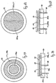
- Figs. 1A and 1B show a pressure sensor according to a first embodiment of this invention, formed on top of a ceramic base member 10.
- a first electrode 11, a pressure-sensitive membrane 13 and a second electrode 14 are sequentially stacked one on top of another in mutually contacting relationship at the center of a surface of the base member 10, and are thereafter covered by a protective membrane 16 (not shown in Fig. 1A).
- the base member 10 may comprise a monocrystalline ceramic material, a polycrystalline ceramic material (such as MoSi 2 , Al 2 O 3 , SiC, and Si 3 N 4 ) or an inorganic material such as glass.
- the base member 10 need not be a plate but may comprise a metallic film or a resin film.
- a metallic film include films of a stainless steel, a copper alloy such as phosphor bronze, aluminum and titanium.
- a resin film include films of polyimide, polyethylene terephthalate, polycarbonate and polyphenylene sulfide.
- the first electrode 11 serves as a part of a capacitor element and is selected in view of its affinity with the base member 10 and the pressure-sensitive membrane 13. It may comprise Cr, Au, Cu, Ag, Al and Ta, as well as an alloy such as AgNi. It may be formed by printing, a thin-film process, sputtering, vapor deposition and ion plating.
- the pressure-sensitive membrane 13 is of a material of which dielectric constant changes according to pressure, such as AlN, GaN, InN, NbN and TaN. It need not be made of a single material. Materials as mentioned above may be combined or stacked, according to given requirements. Its thickness does not limit the scope of the invention, and may be 1 ⁇ m-10 ⁇ m and preferably 2 ⁇ m-5 ⁇ m. If it is thinner than 1 ⁇ m, it may not be found to be sufficiently well insulating. If it is thicker than 10 ⁇ m, it affects the electrostatic capacitance adversely and the production cost increases. A thickness in the range of 3-5 ⁇ m is particularly preferred if AlN is used for the pressure-sensitive membrane. If it is thinner than 3 ⁇ m, pinholes tend to be generated to cause insufficient insulation. If it is thicker than 5 ⁇ m, the electrostatic capacitance becomes too small and its production cost increases.
- the production method of the pressure-sensitive membrane 13 is not intended to limit the scope of the invention. It may be formed by sputtering, ion-plaiting, CVD or PVD.
- the protective membrane 16 may comprise a resin material such as polyimide, glass or SiO 2 . It is to be noted that terminal parts of lead wires 12 and 15 for the first and second electrodes 11 and 14 are not covered by the protective membrane 16.
- numeral 20 schematically represents a circuit of a known kind for measuring the electrostatic capacitance.
- Figs. 2A and 2B show a second embodiment of the present invention, which is similar to the first embodiment described above, different therefrom in that the lead lines 12 and 15 of the first and second electrodes 11 and 14 are extended to the bottom surface of the base member 10 and that the protective membrane 16 covers the entire sensor except the bottom surface of the base member 10.
- This embodiment is advantageous in that it is surface-mountable and hence its assembly is easy.
- Fig. 2C is a variation to the second embodiment described above, different therefrom in that an electrically insulating layer 17 is inserted between the first electrode 11 and the pressure-sensitive membrane 13 and another electrically insulating layer 18 is inserted between the second electrode 14 and the pressure-sensitive membrane 13. This variation is advantageous in that the electrodes 11 and 14 are more dependably insulated from each other.
- Figs. 3A and 3B show a third embodiment of the invention, which is similar to the first embodiment described above, different therefrom in that a pair of connector terminals 17 and 18 penetrates the base member 10 and is connected respectively to the lead lines 12 and 15 of the first and second terminals 11 and 14.
- This embodiment is advantageous in that the sensor element can be handled like a multi-purpose lead component such that all constituent components can be assembled from one side.
- Figs. 4A and 4B show a fourth embodiment of the invention, which is similar to the third embodiment described above, different therefrom in that the upper surface of its base member 10 is entirely covered by the protective membrane 16. Since the bottom ends of the connector terminals 17 and 18 protrude from the bottom surface of the base member 10, a pressure sensor with a dependable insulating characteristic can be obtained by mounting onto a printed circuit board.
- Figs. 5A and 5B show a fifth embodiment of the invention characterized as having its first electrode 11 consisting of a circular central electrode 19a and an annular electrode 19b which are concentric to each other.
- a pair of connector terminals 18 and 17 respectively connects to the central electrode 19a and the annular electrode 19b.
- the sizes of the central and annular electrodes 19a and 19b as well as their ratio may be appropriately varied.
- This embodiment is advantageous in that the shape of the second electrode 14 becomes simpler because the connector terminals 18 and 17 can be connected respectively to the central electrode 19a and the annular electrode 19b which are both formed on the same surface such that the production process becomes easier. Since the functional relationship between the pressure and the dielectric constant becomes linear, it is easier for the measurement of pressure.
- Figs. 6A and 6B show a sixth embodiment characterized wherein the first electrode 11 is formed as a pair of semicircular divided electrodes 20a and 20b.
- This embodiment is advantageous in that it can be produced easily because a pair of connector terminals 17 and 18 can be connected to the first electrode 11 without making its shape complicated.
- Figs. 7D and 7E show a seventh embodiment characterized as having both a pressure sensor and an IC component 24 mounted onto a surface of a film-like base member 21 and connected together.
- a first electrode 11, lead lines 12 and 15 and connector pads 22a, 22b, 22c, 22d, 23a, 23b, 23c and 23d are formed on the surface of a rectangular planar base member made of a polyimide film as shown in Fig. 7A.
- a pressure-sensitive membrane 13 of a strong dielectric material such as AlN is formed by sputtering on the upper surface of the first electrode 11 as shown in Fig. 7B.
- a second electrode 14 is formed on the surface of this pressure-sensitive membrane 13 and this second electrode 14 is connected to the lead line 15 as shown in Fig. 7C. Still thereafter, connector terminals of the IC component 24 are electrically connected individually to the connector pads 22a-22d and 23a-23d, as shown in Figs. 7D and 7E.
- This embodiment is advantageous in that pressure within a normally inaccessible space or inside a sealed space can be detected easily. It may be used, for example, for measuring the pressure inside an automobile tire or may be installed inside a wrist watch to measure the external atmospheric pressure and to have it displayed.
- Fig. 8A shows an example of such a circuit for outputting frequency F out as an indicator of pressure sensed by the pressure-sensitive membrane 13 of the sensor.
- Fig. 8B shows the outputted frequency F out decreases as the sensed pressure increases.
- Fig, 9A shows another example of a circuit for outputting voltage V out as an indicator of pressure sensed by the pressure-sensitive membrane 13 through a half-wave regulator circuit, a smoothing circuit for smoothing the waveform and an amplifier circuit.
- the outputted voltage Vout decreases increases as the sensed pressure increases.
Landscapes
- Physics & Mathematics (AREA)
- General Physics & Mathematics (AREA)
- Measuring Fluid Pressure (AREA)
- Inorganic Insulating Materials (AREA)
Applications Claiming Priority (2)
| Application Number | Priority Date | Filing Date | Title |
|---|---|---|---|
| JP2000397477 | 2000-12-27 | ||
| JP2000397477A JP3932302B2 (ja) | 2000-12-27 | 2000-12-27 | 圧力センサ |
Publications (2)
| Publication Number | Publication Date |
|---|---|
| EP1219940A2 true EP1219940A2 (de) | 2002-07-03 |
| EP1219940A3 EP1219940A3 (de) | 2004-04-07 |
Family
ID=18862594
Family Applications (1)
| Application Number | Title | Priority Date | Filing Date |
|---|---|---|---|
| EP01129860A Ceased EP1219940A3 (de) | 2000-12-27 | 2001-12-14 | Kapazitive Druckwandler |
Country Status (3)
| Country | Link |
|---|---|
| US (1) | US6606911B2 (de) |
| EP (1) | EP1219940A3 (de) |
| JP (1) | JP3932302B2 (de) |
Cited By (1)
| Publication number | Priority date | Publication date | Assignee | Title |
|---|---|---|---|---|
| EP2770380A1 (de) * | 2013-02-21 | 2014-08-27 | The Swatch Group Research and Development Ltd. | Elektronische Vorrichtung, die mit Mitteln zur automatischen Erkennung eines Lecks ausgestattet ist |
Families Citing this family (50)
| Publication number | Priority date | Publication date | Assignee | Title |
|---|---|---|---|---|
| US7420659B1 (en) * | 2000-06-02 | 2008-09-02 | Honeywell Interantional Inc. | Flow control system of a cartridge |
| EP1352210B1 (de) * | 2001-01-10 | 2012-07-25 | Société de Technologie Michelin | Verfahren und vorrichtung zur bestimmung von deformationen und kräften |
| US20060149168A1 (en) * | 2002-08-19 | 2006-07-06 | Robert Czarnek | Capacitive uterine contraction sensor |
| US7152482B2 (en) | 2002-10-01 | 2006-12-26 | National Institute Of Advanced Industrial Science & Technology | Piezoelectric sensor and input device including same |
| ATE533092T1 (de) * | 2003-12-17 | 2011-11-15 | Eta Sa Mft Horlogere Suisse | Tragbares elektronisches gerät, das mit einem drucksensor ausgerüstet ist |
| DE102005003548A1 (de) * | 2004-02-02 | 2006-02-09 | Volkswagen Ag | Bedienelement für ein Kraftfahrzeug |
| JP4777339B2 (ja) * | 2004-04-09 | 2011-09-21 | ソシエテ ド テクノロジー ミシュラン | 変形センサを備えたタイヤと、タイヤの撓みの評価方法 |
| US7222639B2 (en) * | 2004-12-29 | 2007-05-29 | Honeywell International Inc. | Electrostatically actuated gas valve |
| US7328882B2 (en) * | 2005-01-06 | 2008-02-12 | Honeywell International Inc. | Microfluidic modulating valve |
| US7445017B2 (en) * | 2005-01-28 | 2008-11-04 | Honeywell International Inc. | Mesovalve modulator |
| US7517201B2 (en) * | 2005-07-14 | 2009-04-14 | Honeywell International Inc. | Asymmetric dual diaphragm pump |
| US20070051415A1 (en) * | 2005-09-07 | 2007-03-08 | Honeywell International Inc. | Microvalve switching array |
| US7624755B2 (en) | 2005-12-09 | 2009-12-01 | Honeywell International Inc. | Gas valve with overtravel |
| US7523762B2 (en) | 2006-03-22 | 2009-04-28 | Honeywell International Inc. | Modulating gas valves and systems |
| US7543604B2 (en) * | 2006-09-11 | 2009-06-09 | Honeywell International Inc. | Control valve |
| US7644731B2 (en) | 2006-11-30 | 2010-01-12 | Honeywell International Inc. | Gas valve with resilient seat |
| US8079269B2 (en) * | 2007-05-16 | 2011-12-20 | Rosemount Inc. | Electrostatic pressure sensor with porous dielectric diaphragm |
| JP2009145554A (ja) * | 2007-12-13 | 2009-07-02 | Yamaha Corp | 圧力センサおよびデータ入力装置 |
| JP5409251B2 (ja) * | 2008-11-19 | 2014-02-05 | キヤノン株式会社 | 電気機械変換装置およびその製造方法 |
| WO2011122347A1 (ja) * | 2010-03-29 | 2011-10-06 | シャープ株式会社 | タッチパネル機能付き表示装置 |
| JP5365665B2 (ja) * | 2011-06-23 | 2013-12-11 | 横河電機株式会社 | センサユニット |
| WO2013041911A1 (en) * | 2011-09-22 | 2013-03-28 | Honeywell Romania Srl | Iii-nitride strain sensor |
| US9074770B2 (en) | 2011-12-15 | 2015-07-07 | Honeywell International Inc. | Gas valve with electronic valve proving system |
| US8899264B2 (en) | 2011-12-15 | 2014-12-02 | Honeywell International Inc. | Gas valve with electronic proof of closure system |
| US9851103B2 (en) | 2011-12-15 | 2017-12-26 | Honeywell International Inc. | Gas valve with overpressure diagnostics |
| US9995486B2 (en) | 2011-12-15 | 2018-06-12 | Honeywell International Inc. | Gas valve with high/low gas pressure detection |
| US8839815B2 (en) | 2011-12-15 | 2014-09-23 | Honeywell International Inc. | Gas valve with electronic cycle counter |
| US9835265B2 (en) | 2011-12-15 | 2017-12-05 | Honeywell International Inc. | Valve with actuator diagnostics |
| US8905063B2 (en) | 2011-12-15 | 2014-12-09 | Honeywell International Inc. | Gas valve with fuel rate monitor |
| US9846440B2 (en) | 2011-12-15 | 2017-12-19 | Honeywell International Inc. | Valve controller configured to estimate fuel comsumption |
| US9557059B2 (en) | 2011-12-15 | 2017-01-31 | Honeywell International Inc | Gas valve with communication link |
| US8947242B2 (en) | 2011-12-15 | 2015-02-03 | Honeywell International Inc. | Gas valve with valve leakage test |
| US20130201316A1 (en) | 2012-01-09 | 2013-08-08 | May Patents Ltd. | System and method for server based control |
| US9234661B2 (en) | 2012-09-15 | 2016-01-12 | Honeywell International Inc. | Burner control system |
| US10422531B2 (en) | 2012-09-15 | 2019-09-24 | Honeywell International Inc. | System and approach for controlling a combustion chamber |
| WO2014052470A1 (en) * | 2012-09-25 | 2014-04-03 | Arizona Board Of Regents Acting For And On Behalf Of Arizona State University | Electrochemical pressure transducer |
| CN103868631A (zh) * | 2012-12-10 | 2014-06-18 | 黑龙江彩格工业设计有限公司 | 新型弹性压力传感器及其使用方法 |
| EP2868970B1 (de) | 2013-10-29 | 2020-04-22 | Honeywell Technologies Sarl | Regelungsvorrichtung |
| US10024439B2 (en) | 2013-12-16 | 2018-07-17 | Honeywell International Inc. | Valve over-travel mechanism |
| JP2015187561A (ja) * | 2014-03-26 | 2015-10-29 | 株式会社日本自動車部品総合研究所 | 圧力センサ |
| US9841122B2 (en) | 2014-09-09 | 2017-12-12 | Honeywell International Inc. | Gas valve with electronic valve proving system |
| US9645584B2 (en) | 2014-09-17 | 2017-05-09 | Honeywell International Inc. | Gas valve with electronic health monitoring |
| JP6309498B2 (ja) * | 2015-09-11 | 2018-04-11 | 株式会社鷺宮製作所 | 静電容量検出式圧力スイッチ及び圧力センサ |
| US10503181B2 (en) | 2016-01-13 | 2019-12-10 | Honeywell International Inc. | Pressure regulator |
| US10564062B2 (en) | 2016-10-19 | 2020-02-18 | Honeywell International Inc. | Human-machine interface for gas valve |
| EP3652721A1 (de) | 2017-09-04 | 2020-05-20 | NNG Software Developing and Commercial LLC | Verfahren und vorrichtung zum sammeln und verwenden von sensordaten von einem fahrzeug |
| US11073281B2 (en) | 2017-12-29 | 2021-07-27 | Honeywell International Inc. | Closed-loop programming and control of a combustion appliance |
| JP6981885B2 (ja) * | 2018-01-23 | 2021-12-17 | アズビル株式会社 | 静電容量型圧力センサの異常検知方法および装置 |
| US10697815B2 (en) | 2018-06-09 | 2020-06-30 | Honeywell International Inc. | System and methods for mitigating condensation in a sensor module |
| IL296197B2 (en) | 2019-02-19 | 2024-05-01 | Edgy Bees Ltd | Real-time video data stream latency estimation |
Family Cites Families (10)
| Publication number | Priority date | Publication date | Assignee | Title |
|---|---|---|---|---|
| JPS5855732A (ja) * | 1981-09-30 | 1983-04-02 | Hitachi Ltd | 静電容量型圧力センサ |
| JPS58103638A (ja) * | 1981-12-16 | 1983-06-20 | Kureha Chem Ind Co Ltd | 圧力センサ− |
| JPS61164129A (ja) * | 1985-01-16 | 1986-07-24 | Murata Mfg Co Ltd | 圧力センサ− |
| JPS61175538A (ja) * | 1985-01-30 | 1986-08-07 | Nippon Denso Co Ltd | 圧力検出器 |
| FR2679651B1 (fr) * | 1991-07-26 | 1993-11-12 | Schlumberger Services Petroliers | Couche mince extensometrique en cermet a base de tantale et de nitrate de tantale, son procede de preparation et son utilisation dans un capteur de pression. |
| JPH0755615A (ja) | 1993-08-10 | 1995-03-03 | Agency Of Ind Science & Technol | 静電容量型力センサ |
| JPH07191055A (ja) * | 1993-12-27 | 1995-07-28 | Hitachi Ltd | 静電容量式加速度センサ |
| JP3020130B2 (ja) | 1994-02-18 | 2000-03-15 | 工業技術院長 | 圧力測定機能を有する複合材料 |
| JP2000180286A (ja) * | 1998-12-21 | 2000-06-30 | Hitachi Ltd | エンジン用の筒内圧センサとこれを用いた気筒内空気流入量の計測装置 |
| JP2000193546A (ja) * | 1998-12-25 | 2000-07-14 | Tokai Rika Co Ltd | 圧力検知機構付きカテ―テル |
-
2000
- 2000-12-27 JP JP2000397477A patent/JP3932302B2/ja not_active Expired - Lifetime
-
2001
- 2001-12-05 US US10/006,783 patent/US6606911B2/en not_active Expired - Lifetime
- 2001-12-14 EP EP01129860A patent/EP1219940A3/de not_active Ceased
Non-Patent Citations (1)
| Title |
|---|
| WAGNER J.M.; BECHSTEDT F.: "Pressure dependence of the dielectric and lattice-dynamical properties of GaN and AlN", PHYSICAL REVIEW, B. CONDENSED MATTER, vol. 62, no. 7, 15 August 2000 (2000-08-15), AMERICAN INSTITUTE OF PHYSICS. NEW YORK, US, pages 4526 - 4534, XP007904108 * |
Cited By (2)
| Publication number | Priority date | Publication date | Assignee | Title |
|---|---|---|---|---|
| EP2770380A1 (de) * | 2013-02-21 | 2014-08-27 | The Swatch Group Research and Development Ltd. | Elektronische Vorrichtung, die mit Mitteln zur automatischen Erkennung eines Lecks ausgestattet ist |
| US9310272B2 (en) | 2013-02-21 | 2016-04-12 | The Swatch Group Research And Development Ltd | Electronic device provided with automatic leak detection means |
Also Published As
| Publication number | Publication date |
|---|---|
| US6606911B2 (en) | 2003-08-19 |
| JP3932302B2 (ja) | 2007-06-20 |
| EP1219940A3 (de) | 2004-04-07 |
| JP2002195904A (ja) | 2002-07-10 |
| US20020078756A1 (en) | 2002-06-27 |
Similar Documents
| Publication | Publication Date | Title |
|---|---|---|
| US6606911B2 (en) | Pressure sensors | |
| US4388668A (en) | Capacitive pressure transducer | |
| US4207604A (en) | Capacitive pressure transducer with cut out conductive plate | |
| EP0831315B1 (de) | Druckwandler | |
| US4426673A (en) | Capacitive pressure transducer and method of making same | |
| US5186054A (en) | Capacitive pressure sensor | |
| US4177496A (en) | Capacitive pressure transducer | |
| US6051853A (en) | Semiconductor pressure sensor including reference capacitor on the same substrate | |
| US5020377A (en) | Low pressure transducer using metal foil diaphragm | |
| US6222376B1 (en) | Capacitive moisture detector and method of making the same | |
| KR100507942B1 (ko) | 반도체용 압력 센서 | |
| US20070095144A1 (en) | Low cost high-pressure sensor | |
| US8631709B2 (en) | Pressure transducer structures having a plurality of conductive traces for curved surfaces | |
| US6997059B2 (en) | Pressure sensor | |
| EP1571434B1 (de) | Dehnungsdetektor und Drucksensor | |
| US7591194B2 (en) | Data capturing and processing system for a roller bearing and roller bearing with such system | |
| US7240558B2 (en) | Pressure sensor | |
| JPH08122362A (ja) | 静電容量型加速度センサ | |
| JPH05149773A (ja) | ひずみゲ−ジの使用方法 | |
| CN101625058B (zh) | 用于法兰连接的密封装置 | |
| JPH1078363A (ja) | 薄膜型センサ | |
| JP4242977B2 (ja) | 円柱型静電容量式捩り歪みセンサ | |
| US5614673A (en) | Acceleration sensing device | |
| JP2003075277A (ja) | 面状圧力センサ | |
| EP1552260B1 (de) | Drucksensor und dazugehörende herstellung |
Legal Events
| Date | Code | Title | Description |
|---|---|---|---|
| PUAI | Public reference made under article 153(3) epc to a published international application that has entered the european phase |
Free format text: ORIGINAL CODE: 0009012 |
|
| AK | Designated contracting states |
Kind code of ref document: A2 Designated state(s): AT BE CH CY DE DK ES FI FR GB GR IE IT LI LU MC NL PT SE TR |
|
| AX | Request for extension of the european patent |
Free format text: AL;LT;LV;MK;RO;SI |
|
| PUAL | Search report despatched |
Free format text: ORIGINAL CODE: 0009013 |
|
| AK | Designated contracting states |
Kind code of ref document: A3 Designated state(s): AT BE CH CY DE DK ES FI FR GB GR IE IT LI LU MC NL PT SE TR |
|
| AX | Request for extension of the european patent |
Extension state: AL LT LV MK RO SI |
|
| 17P | Request for examination filed |
Effective date: 20040325 |
|
| AKX | Designation fees paid |
Designated state(s): DE FR GB IT |
|
| 17Q | First examination report despatched |
Effective date: 20041206 |
|
| RIC1 | Information provided on ipc code assigned before grant |
Ipc: G01L 9/00 20060101AFI20080211BHEP |
|
| STAA | Information on the status of an ep patent application or granted ep patent |
Free format text: STATUS: THE APPLICATION HAS BEEN REFUSED |
|
| 18R | Application refused |
Effective date: 20081222 |