EP1219949A2 - Dispositif et méthode pour l'estimation de la résistance à la rupture d'une structure en couches - Google Patents
Dispositif et méthode pour l'estimation de la résistance à la rupture d'une structure en couches Download PDFInfo
- Publication number
- EP1219949A2 EP1219949A2 EP01310871A EP01310871A EP1219949A2 EP 1219949 A2 EP1219949 A2 EP 1219949A2 EP 01310871 A EP01310871 A EP 01310871A EP 01310871 A EP01310871 A EP 01310871A EP 1219949 A2 EP1219949 A2 EP 1219949A2
- Authority
- EP
- European Patent Office
- Prior art keywords
- cutting blade
- interface
- depth
- breaking strength
- layered structure
- Prior art date
- Legal status (The legal status is an assumption and is not a legal conclusion. Google has not performed a legal analysis and makes no representation as to the accuracy of the status listed.)
- Withdrawn
Links
Images


Classifications
-
- G—PHYSICS
- G01—MEASURING; TESTING
- G01N—INVESTIGATING OR ANALYSING MATERIALS BY DETERMINING THEIR CHEMICAL OR PHYSICAL PROPERTIES
- G01N3/00—Investigating strength properties of solid materials by application of mechanical stress
- G01N3/40—Investigating hardness or rebound hardness
- G01N3/42—Investigating hardness or rebound hardness by performing impressions under a steady load by indentors, e.g. sphere, pyramid
- G01N3/46—Investigating hardness or rebound hardness by performing impressions under a steady load by indentors, e.g. sphere, pyramid the indentors performing a scratching movement
-
- G—PHYSICS
- G01—MEASURING; TESTING
- G01N—INVESTIGATING OR ANALYSING MATERIALS BY DETERMINING THEIR CHEMICAL OR PHYSICAL PROPERTIES
- G01N19/00—Investigating materials by mechanical methods
- G01N19/04—Measuring adhesive force between materials, e.g. of sealing tape, of coating
-
- G—PHYSICS
- G01—MEASURING; TESTING
- G01N—INVESTIGATING OR ANALYSING MATERIALS BY DETERMINING THEIR CHEMICAL OR PHYSICAL PROPERTIES
- G01N2203/00—Investigating strength properties of solid materials by application of mechanical stress
- G01N2203/0058—Kind of property studied
- G01N2203/006—Crack, flaws, fracture or rupture
- G01N2203/0067—Fracture or rupture
-
- G—PHYSICS
- G01—MEASURING; TESTING
- G01N—INVESTIGATING OR ANALYSING MATERIALS BY DETERMINING THEIR CHEMICAL OR PHYSICAL PROPERTIES
- G01N2203/00—Investigating strength properties of solid materials by application of mechanical stress
- G01N2203/0058—Kind of property studied
- G01N2203/0091—Peeling or tearing
Definitions
- the present invention relates to a layered structure breaking strength estimating method and appratus, more particularly to a method and apparatus for estimating the breaking strength of a layered structure which includes an upper layer and a lower layer.
- a method and an appratus for layered structure breaking strength estimation is characterized by inserting the edge of a cutting blade into the upper layer of the structure, moving the cutting blade substantially in parallel with the interface between the upper layer and the lower layer while the depth of the cutting blade being controlled to such a depth slightly upper than the interface that a cutting piece stays directly on the cutting blade, and measuring a force exerted on the cutting blade substantially in parallel with the interface.
- the cutting blade may be moved when the layered structure remains stationary.
- the layered structure may be moved when the cutting blade remains stationary or both may be moved.
- the force required for cutting close to the interface between the two layers in the layered structure may be used as a criterion for determining the breaking strength of the layered structure.
- measurement of the breaking strength can be biased to the upper layer.
- measurement of the breaking strength can be biased to the lower layer.
- the layered structure breaking strength estimating method and appratus of the first aspect of the present invention is implemented in which while the cutting blade is inserted into the upper layer, maintained at a setting depth slightly upper than the interface with its edge continuously holding directly a cutting piece, and moved substantially in parallel with the interface, a force exerted on the cutting blade substantially in parallel with the interface is measured and used as the criterion for estimating the breaking strength of the layered structure.
- This allows any layered structure which is relatively high in the bonding strength or has an interface located at an obscure depth to be successfully examined for its breaking strength.
- the cutting blade with its edge holding a cutting piece may be monitored using an optical enlarging device.
- a method and an appratus for layered structure breaking strength estimation is characterized by inserting the edge of a cutting blade into the upper layer of the structure andmoving the cutting blade substantially in parallel with the interface between the upper layer and the lower layer, measuring a force exerted on the cutting blade substantially in parallel with the interface, moving the cutting blade substantially in parallel with the interface while the depth of the cutting blade being controlled to such a depth where the force alternates between increase and decrease.
- the cutting blade may be moved when the layered structure remains stationary.
- the layered structure may be moved when the cutting blade remains stationary or both may be moved.
- the force required for cutting close to the interface between the two layers in the layered structure may be used as a criterion for determining the breaking strength of the layered structure.
- measurement of the breaking strength can be biased to the upper layer.
- measurement of the breaking strength can be biased to the lower layer.
- the breaking strength of a layered structure is favorably measured by a manner in which as the cutting blade is inserted at its edge into the upper layer and driven along and substantially in parallel with the interface (which means a virtual plane or not undulated curve extending in the middle of a overlapped portion of the two, upper and lower, layers when the two layers are overlapped, or means an averaged virtual plane or not undulated curve when the interface is undulated), it is favorably controlled to such a desired depth that the force exerted on the cutting blade alternates between increase and decrease. More specifically, this manner allows the force exerted substantially in parallel with the interface to be increased until the layered structure is broken up.
- the layered structure is broken up at its weakest location close to the interface and its physical resistance is sharply declined thus offsetting the force exerted substantially in parallel with the interface. As this action is repeated, the layered structure is broken up at its weakest location close to the interface in cycles. Accordingly, the breaking strength of the layered structure can be measured even when the bonding strength is relatively high or the location of the interface is obscure.
- the layered structure breaking strength estimating method and appratus of the second aspect of the present invention is implemented in which while the cutting blade is inserted into the upper layer, maintained at such a setting depth that the force exerted on the cutting blade substantially in parallel with the interface alternates between increase and decrease, and moved substantially in parallel with the interface, a force exerted on the cutting blade substantially in parallel with the interface is measured and used as the criterion for estimating the breaking strength of the layered structure.
- This allows any layered structure which is relatively high in the bonding strength or has an interface located at an obscure depth to be successfully examined for its breaking strength.
- the force exerted on the cutting blade may be measured using a load cell.
- the method and apparatus for layered structure breaking strength estimation defined in above aspects is modified wherein the force exerted on the cutting blade substantially in parallel with the interface, a force exerted on the cutting blade substantially vertical to the interface, and the depth of the cutting blade are expressed in the form of a graphic profile of change with time.
- the layered structure breaking strength estimating method and appratus of the third aspect of the present invention allows the three factors of the cutting blade during the cutting action to be expressed in graphic profiles thus clarifying the relationship between the factors.
- the force exerted on the cutting blade may be measured using a load cell.
- the depth of the cutting blade may be measured using a displacement meter.
- the method and appratus for layered structure breaking strength estimation described above is modified wherein the unit of displacement of the cutting blade for determining the depth of the edge of the cutting blade is not greater than 2 micro meter.
- fine depth controll can be set with much difficulty.
- the layered structure breaking strength estimating method and appratus of the fourth aspect of the present invention is implemented with the unit of displacement not greater than 2 ⁇ m, thus allowing the depth to be set accurately.
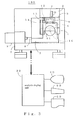
- Fig. 1 is a front view of a layered structure breaking strength estimating apparatus.
- Fig. 2 and Fig. 3 are a right side view and a left side view of the same respectively.
- a layered structure breaking strength estimating apparatus denoted by 100 comprises a sample cutting unit 20, an analysis display unit 30, a monitor 40, an input unit 50, and a printer 60.
- the sample cutting unit 20 includes a bed 1, a sample holder 2 mounted to the bed 1, a transverse slide way 3 supported on the bed 1 for sliding movement in a second direction d2 (See Fig. 2), a longitudinal slide way 4 supported on the traverse slide way 3 for sliding movement in a first direction d1, a transverse load slide way 5 supported on the longitudinal slide way 4 for sliding movement in the second direction d2 (See Fig. 2), a longitudinal load slide way 6 supported on the transverse load slide way 5 for sliding movement in the first direction d1, a cutting blade 7 held to the longitudinal load slide way 6, a transverse driving motor 9 mounted on the bed 1 for driving a transverse ball screw 8 to move the transverse slide way 3 in the second direction d2 (Fig.
- a longitudinal driving motor 11 mounted on the transverse slide way 3 for driving a longitudinal ball screw 10 to move the longitudinal slide way 4 in the first direction d1
- a longitudinal load cell 12 for measuring the longitudinal load Fv exerted on the cutting blade 7 in the first direction d1
- a displacement meter 13 for measuring the cutting depth D in the first direction d1
- a transverse load cell 14 for measuring the transverse load Fc exerted on the cutting blade 7 in the second direction d2
- a camera m mounted to the sample holder 2.
- the first direction d1 and the second direction d2 extend along a horizontal plane and intersect each other at a right angle.
- the sample holder 2 includes a front-side hold-down 2a for holding the front side of a sample S through an access opening provided in the cutting blade 7, a back-side hold-down 2b for pressing the back side of the sample S against the front-side hold-down 2a, and a hold-down screw 2c for tightening the back-side hold-down 2b to the front-side hold-down 2a.
- the sample holder 2 can securely hold the sample S while pressing against its back side. More particularly, the sample S is held at its front side in parallel with the blade line (a straight line along the blade edge) of the cutting blade 7 even if its back side is undulated. The sample S can properly be held regardless of the shape of the sample S.
- the analysis display unit 30 includes an Fv display 30v for displaying measurements of the longitudinal load Fv measured by the longitudinal load cell 12 and their profile of change with time on the monitor 40, a D display 30d for displaying measurements of the cutting depth D measured by the displacement meter 13 and their profile of change with time on the monitor 40, an Fc display 30c for displaying measurements of the transverse load Fc measured by the transverse load cell 14 and their profile of change with time on the monitor 40, an enlargement display 30q for displaying on the monitor 40 an enlarged view of the cutting condition pictured by the camera m, a three-profile simultaneous display 30g for displaying three profiles of change with time of the longitudinal load Fv, the cutting depth D, and the transverse load Fc at once on the monitor 40, a cutting depth setting 30s for presetting the cutting depth, a longitudinal load lowermost number setting 30f for presetting the number of lowermost points of the longitudinal load, and a cutting depth controller 30m for controlling the cutting depth D.
- an Fv display 30v for displaying measurements of the longitudinal
- the cutting depth controller 30m controls the cutting depth to a setting level predetermined by the cutting depth setting 30s. Also, the cutting depth controller 30m controls the cutting depth to cut in to the depth until the number of the lowermost points on the profile of change of the longitudinal load Fv with time reaches to the value predetermined by the longitudinal load lowermost number setting 30f and keeps the depth. Also, upon receiving an instruction for automatic transverse load tracing action from the input unit 50, the cutting depth controller 30m controls the cutting depth to such a level that the transverse load Fc alternates between increase and decrease. Moreover, in response to an instruction for increasing or decreasing the cutting depth from the input unit 50, the cutting depth controller 30m increases or decreases the cutting depth by a unit distance at each instruction. The unit distance may be 2 ⁇ m.
- the sample S may be analyzed by the layered structure breaking strength estimating apparatus 100 using one of the following procedures.
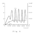
- Fig. 6 illustrates a profile of change with time of the longitudinal load Fv, the cutting depth D, and the transverse load Fc.
- the transverse load Fc alternates between increase and decrease.
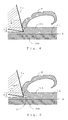
- the transverse load Fc is increased when the peeling stops, as shown in Fig. 4, and decreased when the peeling C runs instantly as shown in Fig . 5. This is repeated as the cutting action goes.
- the cutting depth D is kept uniform as close to the interface B.
- the longitudinal load Fv stays almost zero when the depth D is uniform.
- the breaking strength of the sample S having a layered structure can be estimated from the maximum, minimum, amplitude, cycle, and average of the transverse load Fc.
- the layered structure breaking strength estimating apparatus 100 has the following advantages.
- the method of layered structure breaking strength estimation according to the present invention provides a new criterion for estimating the breaking strength of a layered structure having an upper layer and a lower layer. For example, this method will particularly be useful for estimating the strength of coatings of an automobile or an enclosure.
Landscapes
- Physics & Mathematics (AREA)
- Health & Medical Sciences (AREA)
- Life Sciences & Earth Sciences (AREA)
- Chemical & Material Sciences (AREA)
- Analytical Chemistry (AREA)
- Biochemistry (AREA)
- General Health & Medical Sciences (AREA)
- General Physics & Mathematics (AREA)
- Immunology (AREA)
- Pathology (AREA)
- Sampling And Sample Adjustment (AREA)
- Investigating Strength Of Materials By Application Of Mechanical Stress (AREA)
Applications Claiming Priority (2)
| Application Number | Priority Date | Filing Date | Title |
|---|---|---|---|
| JP2000396343A JP4061524B2 (ja) | 2000-12-27 | 2000-12-27 | 積層構造破壊強度評価方法 |
| JP2000396343 | 2000-12-27 |
Publications (2)
| Publication Number | Publication Date |
|---|---|
| EP1219949A2 true EP1219949A2 (fr) | 2002-07-03 |
| EP1219949A3 EP1219949A3 (fr) | 2004-01-28 |
Family
ID=18861655
Family Applications (1)
| Application Number | Title | Priority Date | Filing Date |
|---|---|---|---|
| EP01310871A Withdrawn EP1219949A3 (fr) | 2000-12-27 | 2001-12-24 | Dispositif et méthode pour l'estimation de la résistance à la rupture d'une structure en couches |
Country Status (3)
| Country | Link |
|---|---|
| US (1) | US6792812B2 (fr) |
| EP (1) | EP1219949A3 (fr) |
| JP (1) | JP4061524B2 (fr) |
Cited By (3)
| Publication number | Priority date | Publication date | Assignee | Title |
|---|---|---|---|---|
| WO2004025280A1 (fr) * | 2002-09-12 | 2004-03-25 | 3M Innovative Properties Company | Appareil destine a mesurer l'adhesion de polymeres gelifies |
| DE102008041133A1 (de) * | 2008-08-08 | 2010-02-11 | Federal-Mogul Wiesbaden Gmbh | Verfahren und Vorrichtung zur Bestimmung der Bindungsfestigkeit in einem Verbundwerkstoff |
| CN114965136A (zh) * | 2022-04-29 | 2022-08-30 | 清华大学深圳国际研究生院 | 一种仿古刀剑锋利度测试方法和测试装置 |
Families Citing this family (9)
| Publication number | Priority date | Publication date | Assignee | Title |
|---|---|---|---|---|
| DE102005057994A1 (de) * | 2005-12-05 | 2007-06-06 | Süss Microtec Lithography Gmbh | Verfahren und Vorrichtung zum Bestimmen der Bondfestigkeit gebondeter Wafer |
| JP4935767B2 (ja) * | 2008-06-19 | 2012-05-23 | トヨタ自動車株式会社 | 破壊強度測定方法 |
| JP5681563B2 (ja) * | 2011-05-19 | 2015-03-11 | 株式会社神戸製鋼所 | 密着性評価方法 |
| JP6797599B2 (ja) * | 2016-08-12 | 2020-12-09 | 学校法人 芝浦工業大学 | 材料の変形特性値を測定する方法 |
| KR102869218B1 (ko) * | 2019-12-09 | 2025-10-10 | 현대자동차주식회사 | 막-전극 접합체의 전극 내부 측정 방법 |
| WO2024097520A1 (fr) * | 2022-11-01 | 2024-05-10 | Dow Global Technologies Llc | Dispositif de test de raclage pour caractériser des formulations d'échantillon |
| CN115901609A (zh) * | 2022-11-08 | 2023-04-04 | 上海理工大学 | 一种叠层材料切削性能测试装置和方法 |
| KR20240086127A (ko) * | 2022-12-09 | 2024-06-18 | 에스케이하이닉스 주식회사 | 웨이퍼 접합 강도의 측정 장치 및 이의 구동 방법, 그리고 웨이퍼 접합 강도의 측정 방법 |
| JP7813272B2 (ja) * | 2023-12-25 | 2026-02-12 | ダイプラ・ウィンテス株式会社 | 試料分析方法及び試料分析装置 |
Family Cites Families (6)
| Publication number | Priority date | Publication date | Assignee | Title |
|---|---|---|---|---|
| JPH0726908B2 (ja) * | 1988-01-25 | 1995-03-29 | 三菱電機株式会社 | 塗膜付着強度又は剪断強度測定装置 |
| US5101655A (en) * | 1990-06-29 | 1992-04-07 | Harvard Industries-The Kingston Warren Corp. | Apparatus and method for weatherstrip wear testing |
| JP2866227B2 (ja) * | 1991-09-19 | 1999-03-08 | 大日本プラスチックス株式会社 | 材料強度測定装置 |
| US5546797A (en) * | 1995-04-11 | 1996-08-20 | The United States Of America As Represented By The Secretary Of The Navy | Constant-depth scratch test for the quantification of interfacial shear strength at film-substrate interfaces |
| US6050139A (en) * | 1998-04-07 | 2000-04-18 | S. D. Warren Services Company | Devices and methods for testing tack uniformity of a coating on a substrate |
| JP3273026B2 (ja) * | 1998-09-02 | 2002-04-08 | 株式会社ミツトヨ | 表面追従型測定機 |
-
2000
- 2000-12-27 JP JP2000396343A patent/JP4061524B2/ja not_active Expired - Lifetime
-
2001
- 2001-12-24 EP EP01310871A patent/EP1219949A3/fr not_active Withdrawn
- 2001-12-26 US US10/033,434 patent/US6792812B2/en not_active Expired - Fee Related
Cited By (4)
| Publication number | Priority date | Publication date | Assignee | Title |
|---|---|---|---|---|
| WO2004025280A1 (fr) * | 2002-09-12 | 2004-03-25 | 3M Innovative Properties Company | Appareil destine a mesurer l'adhesion de polymeres gelifies |
| DE102008041133A1 (de) * | 2008-08-08 | 2010-02-11 | Federal-Mogul Wiesbaden Gmbh | Verfahren und Vorrichtung zur Bestimmung der Bindungsfestigkeit in einem Verbundwerkstoff |
| CN114965136A (zh) * | 2022-04-29 | 2022-08-30 | 清华大学深圳国际研究生院 | 一种仿古刀剑锋利度测试方法和测试装置 |
| CN114965136B (zh) * | 2022-04-29 | 2024-10-22 | 清华大学深圳国际研究生院 | 一种仿古刀剑锋利度测试方法和测试装置 |
Also Published As
| Publication number | Publication date |
|---|---|
| EP1219949A3 (fr) | 2004-01-28 |
| JP2002195938A (ja) | 2002-07-10 |
| US20020095996A1 (en) | 2002-07-25 |
| US6792812B2 (en) | 2004-09-21 |
| JP4061524B2 (ja) | 2008-03-19 |
Similar Documents
| Publication | Publication Date | Title |
|---|---|---|
| US6792812B2 (en) | Method and apparatus for layered structure breaking strength estimation | |
| CN107379285B (zh) | 一种瓷砖自动切割装置 | |
| KR101847591B1 (ko) | 굽힘에 의해 코팅 평판 제품의 마모 특성을 결정하기 위한 방법 및 장치 | |
| EP1710048B1 (fr) | Instrument de mesure de la forme de surface d'un tampon a polir, procede d'utilisation de l' instrument de mesure de la forme de surface du tampon a polir, procede de mesure de l'angle d'apex du cone du tampon a polir, tampon a polir cmp et procede de fabrication d'un dispositif semi-conducteur | |
| EP1770428B1 (fr) | Microscope et procédé pour la mise au point automatique d'un microscope | |
| KR102518982B1 (ko) | 드로스 제거 장치, 드로스 제거 방법, 드로스 검출 장치 및 드로스 검출 방법 | |
| EP2291635B1 (fr) | Evaluation de surface utilisant une mesure de force orthogonale | |
| EP1855115B1 (fr) | Aspirateur de liquides et analyseur le comprenant | |
| KR20130141485A (ko) | 폐쇄-루프 실리콘 에칭 제어 방법 및 시스템 | |
| US6591659B1 (en) | Process for the determination of the friction properties of sheet metal during forming and the measuring apparatus for carrying out the process | |
| CN109507055B (zh) | 一种测量紧固件硬度分布的方法 | |
| JP4849405B2 (ja) | 自動薄切装置及び自動薄切方法 | |
| JP2000146789A (ja) | 引張り試験方法及び引張り試験装置 | |
| CN114965136B (zh) | 一种仿古刀剑锋利度测试方法和测试装置 | |
| JP4007067B2 (ja) | 基材表面層の強度の測定方法及び装置 | |
| CN107907434B (zh) | 微纳米非均匀材料界面相形貌判断方法 | |
| CN118322374A (zh) | 切割方法、切割系统及切割设备 | |
| CN105290424B (zh) | 一种用于去除样棒表面氧化皮层的车床 | |
| WO2023200995A1 (fr) | Système et procédé de mesure de ductilité et de ténacité de matériau à l'aide de lames de coupe | |
| CN116296801A (zh) | 一种汽车水箱耐压检测机 | |
| WO2000047383A1 (fr) | Appareil et procedes permettant de couper en tranches des lingots de silicium monocristallin | |
| JP2025101574A (ja) | 試料分析方法及び試料分析装置 | |
| JPH10281964A (ja) | 化粧仕上げ材の耐傷性評価方法及び引きかき試験機 | |
| JP4748539B2 (ja) | パイプ間融着力の測定装置及びその測定方法 | |
| JP4066917B2 (ja) | 溶射皮膜の密着力評価装置 |
Legal Events
| Date | Code | Title | Description |
|---|---|---|---|
| PUAI | Public reference made under article 153(3) epc to a published international application that has entered the european phase |
Free format text: ORIGINAL CODE: 0009012 |
|
| AK | Designated contracting states |
Kind code of ref document: A2 Designated state(s): AT BE CH CY DE DK ES FI FR GB GR IE IT LI LU MC NL PT SE TR |
|
| AX | Request for extension of the european patent |
Free format text: AL;LT;LV;MK;RO;SI |
|
| PUAL | Search report despatched |
Free format text: ORIGINAL CODE: 0009013 |
|
| AK | Designated contracting states |
Kind code of ref document: A3 Designated state(s): AT BE CH CY DE DK ES FI FR GB GR IE IT LI LU MC NL PT SE TR |
|
| AX | Request for extension of the european patent |
Extension state: AL LT LV MK RO SI |
|
| RIC1 | Information provided on ipc code assigned before grant |
Ipc: 7G 01N 3/24 B Ipc: 7G 01N 3/46 B Ipc: 7G 01N 19/04 A |
|
| 17P | Request for examination filed |
Effective date: 20040517 |
|
| AKX | Designation fees paid |
Designated state(s): DE FR GB |
|
| 17Q | First examination report despatched |
Effective date: 20050405 |
|
| STAA | Information on the status of an ep patent application or granted ep patent |
Free format text: STATUS: THE APPLICATION HAS BEEN WITHDRAWN |
|
| 18W | Application withdrawn |
Effective date: 20051101 |