EP1219971A2 - Verfahren zur Kühlung einer RF-Spule und Vorrichtung zur Bilderzeugung mittels magnetischer Resonanz, umfassend eine flüssiggekühlte RF-Spule - Google Patents
Verfahren zur Kühlung einer RF-Spule und Vorrichtung zur Bilderzeugung mittels magnetischer Resonanz, umfassend eine flüssiggekühlte RF-Spule Download PDFInfo
- Publication number
- EP1219971A2 EP1219971A2 EP01310475A EP01310475A EP1219971A2 EP 1219971 A2 EP1219971 A2 EP 1219971A2 EP 01310475 A EP01310475 A EP 01310475A EP 01310475 A EP01310475 A EP 01310475A EP 1219971 A2 EP1219971 A2 EP 1219971A2
- Authority
- EP
- European Patent Office
- Prior art keywords
- coil
- space
- shield
- conduit
- gradient coils
- Prior art date
- Legal status (The legal status is an assumption and is not a legal conclusion. Google has not performed a legal analysis and makes no representation as to the accuracy of the status listed.)
- Withdrawn
Links
Images



Classifications
-
- G—PHYSICS
- G01—MEASURING; TESTING
- G01R—MEASURING ELECTRIC VARIABLES; MEASURING MAGNETIC VARIABLES
- G01R33/00—Arrangements or instruments for measuring magnetic variables
- G01R33/20—Arrangements or instruments for measuring magnetic variables involving magnetic resonance
- G01R33/28—Details of apparatus provided for in groups G01R33/44 - G01R33/64
- G01R33/32—Excitation or detection systems, e.g. using radio frequency signals
- G01R33/34—Constructional details, e.g. resonators, specially adapted to MR
- G01R33/34015—Temperature-controlled RF coils
- G01R33/3403—Means for cooling of the RF coils, e.g. a refrigerator or a cooling vessel specially adapted for housing an RF coil
-
- G—PHYSICS
- G01—MEASURING; TESTING
- G01R—MEASURING ELECTRIC VARIABLES; MEASURING MAGNETIC VARIABLES
- G01R33/00—Arrangements or instruments for measuring magnetic variables
- G01R33/20—Arrangements or instruments for measuring magnetic variables involving magnetic resonance
- G01R33/28—Details of apparatus provided for in groups G01R33/44 - G01R33/64
- G01R33/32—Excitation or detection systems, e.g. using radio frequency signals
- G01R33/34—Constructional details, e.g. resonators, specially adapted to MR
-
- G—PHYSICS
- G01—MEASURING; TESTING
- G01R—MEASURING ELECTRIC VARIABLES; MEASURING MAGNETIC VARIABLES
- G01R33/00—Arrangements or instruments for measuring magnetic variables
- G01R33/20—Arrangements or instruments for measuring magnetic variables involving magnetic resonance
- G01R33/28—Details of apparatus provided for in groups G01R33/44 - G01R33/64
- G01R33/32—Excitation or detection systems, e.g. using radio frequency signals
- G01R33/34—Constructional details, e.g. resonators, specially adapted to MR
- G01R33/34015—Temperature-controlled RF coils
- G01R33/34023—Superconducting RF coils
Definitions
- the field of the invention is nuclear magnetic resonance imaging methods and systems. More particularly, the invention relates to an MRI system that includes a liquid cooling system that is at least partially disposed within a system RF shield.
- any nucleus which possesses a magnetic moment attempts to align itself with the direction of the magnetic field in which it is located. In doing so, however, the nucleus precesses around this direction at a characteristic angular frequency (Larmor frequency) which is dependent on the strength of the magnetic field and on the properties of the specific nuclear species (the magnetogyric constant ⁇ of the nucleus). Nuclei which exhibit this phenomena are referred to herein as "spins".
- a region of interest i.e., a region of human tissue for which an MRI image is to be generated
- polarizing field B 0 a uniform magnetic field
- the individual magnetic moments of the spins in the region attempt to align with the polarizing field, but precess about the direction of the field in random order at their characteristic Larmor frequencies.
- a net magnetic moment M z is produced in the direction of the polarizing field, but the randomly oriented magnetic components in the perpendicular, or transverse, plane (x-y plane) cancel one another.
- the net aligned moment Mz may be "tipped" into the x-y plane to produce a net transverse magnetic moment M t which is rotating or spinning in the x-y plane at the Larmor frequency.
- the practical value of this phenomenon resides in the signal that is emitted by the excited spins after the excitation signal B 1 is terminated. While the signal emitted by a single spin is extremely small and difficult to detect, where a portion of the region of interest includes many emitting nuclei, the strength of the emitted signal is appreciable and can be detected.
- the emitted NMR signals are digitized and processed to generate an NMR data set.
- each NMR signal can be encoded with spatial information. While there are many different schemes for encoding position information in NMR signals, an exemplary position encoding technique is commonly referred to as "spin-warp".
- spatial encoding is accomplished by employing three magnetic gradient fields (G x , G y , and G z ) which have the same direction as polarizing field B 0 and which have gradients along the x, y and z axes, respectively.
- G x , G y , and G z magnetic gradient fields
- the spatial distribution of spin excitation can be controlled and the point of origin of the resulting NMR signals can be identified.
- a typical MRI system includes an excitation coil, an RF coil and a plurality of gradient coils that together control the magnetic fields required to generate MR signals needed for imaging purposes.
- Each of the gradient coils generally includes a multiplicity of turns of conductive wire, with total lengths of up to several hundred meters.
- MRI systems position the RF coil inside the gradient coils and include a shield positioned between the RF coil and the gradient coils. An RF space is thus formed within RF shield and the RF coil is disposed within the RF space.
- liquid cooling systems have worked well for the purpose of cooling gradient coils, such systems have not been applied to cooling system components that reside inside the RF space such as the RF coils, the patient support table, etc.
- the primary reason for not providing a liquid cooled configuration that extends into the RF space is that coolant hydrogen atoms, like human tissue, include a large number of protons that, when inside the RF shield, tend to generate NMR signals. These spurious signals, like the signals generated by the excited human tissue, are detected by the detector coils and distort the resulting data and associated images.
- liquid cooling systems have been limited to areas outside the RF shield to avoid spurious signal excitation and air cooling systems have been employed for cooling the RF coils.
- An exemplary embodiment of the invention includes an apparatus for reducing MRI system operating temperature where the MRI system includes an RF coil, a set of gradient coils and an RF shield, the RF shield formed about an RF space, the RF coil positioned within the RF space and formed about an imaging area and the gradient coils formed about the RF shield such that the shield de-couples the RF coil from the gradient coils.
- the apparatus comprises a liquid cooling source positioned outside the RF space; a pump linked to the source for pumping coolant therefrom; and at least one conduit linked to the pump to receive liquid pumped thereby and including at least a conduit portion that extends into the RF space such that at least a portion of the heat generated within or migrated into the RF space is absorbed by the conduit portion and the liquid flowing therein.
- the liquid may be essentially devoid of protons.
- the liquid may be essentially devoid of hydrogen atoms and in fact may be devoid of hydrogen atoms.
- the system may further include at least one of a patient support table, a patient enclosure wall and a receiver coil within the RF space and the conduit portion that extends into the RF space may be proximate at least one of the RF coil, patient support table, patient enclosure wall and receiver coil so that heat generated by the at least one of the coils, table and wall or that migrates into the space is absorbed by the conduit.
- the conduit may include at least a portion that is in direct contact with the RF coil.
- the conduit may include a conduit configuration including many conduits that are positioned throughout the RF coil to absorb heat from various parts of the coil.
- the conduits may be embedded within the RF coil.
- the conduit may be embedded at least in part in either the table or the patient enclosure wall or may be at least in contact with one or both.
- the source includes a heat rejecter and the conduit forms a closed circuit that passes from the pump back to the heat rejecter.
- the MRI system also includes heat generating components outside the RF space and the conduit also includes a second conduit portion that extends outside the RF space and proximate the heat generating components outside the RF space so as to absorb heat from the heat generating components.
- the invention also includes a method for reducing MRI system operating temperature where the MRI system includes an RF coil, a set of gradient coils and an RF shield, the RF shield formed about an RF space, the RF coil positioned within the RF space and formed about an imaging area and the gradient coils formed about the RF shield such that the shield de-couples the RF coil from the gradient coils.
- the method comprises the steps of: providing a liquid cooling source positioned outside the RF space; providing a conduit including at least a portion that extends into the RF space such that at least a portion of the heat generated within the RF space is absorbed by the conduit portion and the liquid flowing therein; and pumping coolant from the source through the conduit.
- the liquid may be essentially devoid of protons.
- the liquid may also be essentially devoid or totally devoid of hydrogen atoms.
- the system may also include at least one of a patient support table, a receiver coil and a patient enclosure wall and the step of providing the conduit may include providing the conduit such that the conduit portion that extends into the RF space is proximate at least a portion of the RF coil so that heat generated by the coil or migrated into the coil is absorbed by the conduit.
- the step of providing the conduit may include providing at least a portion that is in direct contact with the RF coil.
- the step of providing the conduit may include the step of providing a conduit configuration including many conduits that are positioned throughout the RF coil to absorb heat from various parts of the coil.
- the method may include providing the conduit includes providing at least a part of the conduit embedded within one of the RF coil, the support, the enclosure and the receiver coil.
- Fig. 1 there is shown the major components of a preferred MRI system which incorporates the present invention.
- the components illustrated include an operators console 100, a computer system 107, a system control 122, a set of gradient amplifiers 127, a physiological acquisition controller 129, a scan room interface 133, a positioning system 134, amplifiers 153 and 151, a switch 154, a patient support table 20, a heat rejecter 22, a fluid pump 24 and field generating and data collecting system collectively referred to by numeral 26.
- System 26 includes a gradient coil set collectively referred to by numerals 139 and 140, a polarizing magnet (not illustrated but within housing 28), an RF coil 152, a housing 28, an RF shield 30 and a patient enclosure wall 32.
- Wall 32 forms an annular receiving or imaging area 34 for receiving table 20 and a patient supported thereon.
- RF coil 152 is formed about wall 32 and is surrounded by RF shield 30.
- Shield 30 is in turn surrounded by polarizing magnet and gradient coils 139 and 140.
- Shield 30 is provided to de-couple the RF and gradient coils and various constructions of the shield are well know in the MRI art.
- shield 30 forms an "RF space" 40 in which the RF coil and the enclosure wall 32 reside.
- each tube is linked to pump 24 and heat rejecter 22 via inlet and outlet conduits 52, 54, respectively, to form a closed circuit from rejecter 22 through pump 24 to the coils and back again to the rejecter 22.
- cooling liquid can be provided to the field generating system components that reside outside the RF space 40.
- the invention also includes a series of hermetically sealed conduits or tubes collectively referred to by numeral 42 positioned within the RF space 40 to cool system components therein.
- the system in Fig. 1 includes liquid cooling for the RF coil 152 inside the RF space and does not illustrate cooling of other components inside the RF space.
- Subsequent figures illustrate additional embodiments where coolant is used to cool other components in the RF space including the patient enclosure wall 32 and the patient support table 20.
- Each tube 42 is linked to pump 24 and heat rejecter 22 via inlet and outlet conduits 56 and 58, respectively, to form a closed circuit from rejecter 22 through pump 24 to the coils and back again to the rejecter 22. In this manner cooling liquid can be provided to any of the components that reside inside the RF space 40.
- the advantages of a system that can employ a liquid coolant are many and include, among others, enhanced patient comfort, increased RF currents, increased system performance in terms of resolution, a reduced size as air ducts required by prior air cooled systems can be eliminated, and greater overall system efficiency.
- operation of the system illustrated is controlled from operator console 100 that includes a keyboard and control panel 102 and a display 104.
- the console 100 communicates through a link 116 with separate computer system 107 that enables an operator to control the production and display of images on the screen 104.
- the computer system 107 includes a number of modules that communicate with each other through a backplane. These include an image processor module 106, a CPU module 108 and a memory module 113, known in the art as a frame buffer for storing image data arrays.
- the computer system 107 is linked to a disk storage 111 and a tape drive 112 for storage of image data and programs, and it communicates with separate system control 122 through a high speed serial link 115.
- the system control 122 includes a set of modules connected together by a backplane. These include a CPU module 119 and a pulse generator module 121 that connects to the operator console 100 through a serial link 125. It is through this link 125 that the system control 122 receives commands from the operator that indicate the scan sequence to be performed.
- the pulse generator module 121 includes field specifying circuitry that comprises both RF electronics and gradient controlling electronics required to operate the system components to carry out the desired scan sequence. To this end module 121 produces data that indicates the timing, strength and shape of the RF pulses which are to be produced, and the timing of and length of the data acquisition window. The pulse generator module 121 also connects to the set of gradient amplifiers 127, to indicate the timing and shape of the gradient pulses to be produced during the scan.
- the pulse generator module 121 also receives patient data from the physiological acquisition controller 129 that receives signals from a number of different sensors connected to the patient, such as ECG signals from electrodes or respiratory signals from a bellows. And finally, the pulse generator module 121 connects to the scan room interface circuit 133 that receives signals from various sensors associated with the condition of the patient and the magnet system. It is also through the scan room interface circuit 133 that the patient positioning system 134 receives commands to move the patient support table 20 to the desired position for a scan.
- the gradient waveforms produced by the pulse generator module 121 are applied to the gradient amplifier set 127 comprised of G[x], G[y ]and G[z] amplifiers.
- Each gradient amplifier excites a corresponding gradient coil in an assembly generally designated 139 and 140 to produce the magnetic field gradients used for position encoding acquired signals.
- the gradient coil assembly 139 forms part of a magnet assembly 141 which includes a polarizing magnet (not illustrated) and an RF coil 152.
- a transceiver module 150 in the system control 122 produces pulses that are amplified by an RF amplifier 151 that is coupled to the RF coil 152.
- the resulting signals radiated by the excited nuclei in the patient may be sensed by the same RF coil 152 and coupled through the transmit/receive switch 154 to a preamplifier 153.
- the amplified NMR signals are demodulated, filtered, and digitized in the receiver section of the transceiver 150.
- the transmit/receive switch 154 is controlled by a signal from the pulse generator module 121 to electrically connect the RF amplifier 151 to the coil 152 during the transmit mode and to connect the preamplifier 153 during the receive mode.
- the transmit/receive switch 154 also enables a separate local RF coil (for example, a head coil or surface coil) to be used in either the transmit or receive mode.
- the NMR signals picked up by the RF coil 152 are digitized by the transceiver module 150 and transferred to a memory module 160 in the system control 122.
- an array processor 161 When a scan is completed and an entire array of data has been acquired in the memory module 160, an array processor 161 operates to Fourier transform the data into an array of image data. This image data is conveyed through the serial link 115 to the computer system 107 where it is stored in the disk memory 111. In response to commands received from the operator console 100, this image data may be archived on the tape drive 112, or it may be further processed by the image processor 106 and conveyed to the operator console 100 and presented on the display 104.
- control 121 also includes a pump control that is linked via a line 202 to pump 24.
- Control 200 turns on pump 24 during imaging sessions and may continue to drive pump 24 for a time after each imaging session to cool system components.
- control 200 may be equipped to receive feedback information from system 26 that can be used to fine tune the temperature of system 26 components and the ambient within imaging area 34. Systems for controlling temperature based on feedback current are well known in the controls art generally.
- the heat rejecter 22 and pump 24 may be linked to the patient support table 20 to cool the table 20 and maintain the table temperature below the temperature required by regulation.
- the maximum table temperature allowed in an MRI system there are regulations that stipulate the maximum table temperature allowed in an MRI system.
- the table 20 heats up due to heat generated by the RF coils 152 and therefore, the current through coils 152 has to be minimized so that table 20 does not heat up.
- the temperature of table 20 can be easily controlled to be below the regulated temperature and therefore coil current can be increased appreciably.
- rejecter 22 and pump 24 may be linked directly to the patient enclosure wall 32 for cooling wall 32 and maintaining a comfortable ambient temperature within imaging space 34.
- the cooling tube may either be in contact with wall 32 or may be embedded within the wall and the pattern of cooling tubes associated with wall 32 may take may different forms (i.e., linear along the length of wall 32, spirally around the wall 32, having tubes on the inside or the outside of wall 32, etc.).
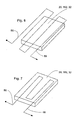
- a block representing a heat generating system component that may reside inside RF space 40 is illustrated and identified by numerals 20 (i.e., the table) 152 (i.e., the RF coil) and 32 (i.e., the wall).
- the table 56-58 is proximate the block
- tube 56, 58 is in contact with the block
- Fig. 8 the tube 56-58 is partially embedded within the block.
- rejecter 22 and pump 24 may be linked separately to each component within the RF space 40, it is also contemplated that components to be cooled within space 40 could be linked in series. In addition, it is contemplated that components within RF space 40 and that reside outside space 40 that have to be cooled could be linked in series with a second portion of the conduit outside the RF space. For example, gradient coils 139 and 140 and RF coils 152 in Fig. 1 could be linked in series with pump 24 and heat rejecter 22. Moreover referring also to Fig. 1, any system components illustrated in Fig. 1 that need to dissipate heat could be linked in series or separately to rejecter 22 and pump 24.
- RF electronics inside pulse generator module 121 could be linked to rejecter 22 and pump 24 for cooling purposes.
- FIG. 4 an exemplary series linkage of system components is illustrated and includes table 20, RF coil 152, RF electronics (e.g., 121), a block 60 indicating any other components that need to dissipate heat and heat rejecter 22.
- a non-hydrogen based fluid source is provided outside the RF space.
- a conduit is provided that extends at least in part into the RF space and is juxtaposed so as to absorb heat from components within the RF space.
- the conduit portion that extends into the RF space may be juxtaposed adjacent the RF coil or may be embedded within the RF coil or may be in contact with the RF coil.
- the conduit portion within the RF space may be positioned adjacent the patient support bed, may extend within the support bed or may contact the outside surface of the support bed.
- coolant is pumped through the conduit so as to cool components within the RF space.
Landscapes
- Physics & Mathematics (AREA)
- Condensed Matter Physics & Semiconductors (AREA)
- General Physics & Mathematics (AREA)
- Thermal Sciences (AREA)
- Magnetic Resonance Imaging Apparatus (AREA)
Applications Claiming Priority (2)
| Application Number | Priority Date | Filing Date | Title |
|---|---|---|---|
| US09/740,439 US20020073717A1 (en) | 2000-12-19 | 2000-12-19 | MR scanner including liquid cooled RF coil and method |
| US740439 | 2000-12-19 |
Publications (2)
| Publication Number | Publication Date |
|---|---|
| EP1219971A2 true EP1219971A2 (de) | 2002-07-03 |
| EP1219971A3 EP1219971A3 (de) | 2004-03-24 |
Family
ID=24976513
Family Applications (1)
| Application Number | Title | Priority Date | Filing Date |
|---|---|---|---|
| EP01310475A Withdrawn EP1219971A3 (de) | 2000-12-19 | 2001-12-14 | Verfahren zur Kühlung einer RF-Spule und Vorrichtung zur Bilderzeugung mittels magnetischer Resonanz, umfassend eine flüssiggekühlte RF-Spule |
Country Status (3)
| Country | Link |
|---|---|
| US (1) | US20020073717A1 (de) |
| EP (1) | EP1219971A3 (de) |
| JP (1) | JP2002224084A (de) |
Cited By (6)
| Publication number | Priority date | Publication date | Assignee | Title |
|---|---|---|---|---|
| DE102004006551B4 (de) * | 2004-02-10 | 2007-01-25 | Siemens Ag | Verfahren zur Erzeugung von Magnetresonanzaufnahmen eines Untersuchungsobjekts, dielektrisches Element, Magnetresonanzsystem und Steuereinrichtung für ein Magnetresonanzsystem |
| WO2008037636A1 (de) * | 2006-09-26 | 2008-04-03 | Siemens Aktiengesellschaft | Detektionseinheit zur anordnung in einer felderzeugungseinheit eines mr-geräts |
| US7557577B2 (en) | 2003-12-08 | 2009-07-07 | Siemens Aktiengesselschaft | Water-soluble paramagnetic substance reducing the relaxation time of the coolant in an MRI system |
| WO2009004521A3 (en) * | 2007-07-02 | 2009-10-15 | Koninklijke Philips Electronics N.V. | Thermally stabilized pet detector for hybrid pet-mr system |
| DE102004038237B4 (de) * | 2003-08-07 | 2013-10-02 | Ge Medical Systems Global Technology Company, Llc | Einrichtung zur aktiven Kühlung eines MRI-Patiententunnels bei zylindrischen MRI-Systemen |
| EP3431059A1 (de) * | 2017-07-20 | 2019-01-23 | Koninklijke Philips N.V. | Patiententrage zur medizinischen behandlung oder untersuchung mit kühlpad |
Families Citing this family (29)
| Publication number | Priority date | Publication date | Assignee | Title |
|---|---|---|---|---|
| US7379769B2 (en) * | 2003-09-30 | 2008-05-27 | Sunnybrook Health Sciences Center | Hybrid imaging method to monitor medical device delivery and patient support for use in the method |
| US7970452B2 (en) * | 2003-09-30 | 2011-06-28 | Hologic, Inc. | Open architecture imaging apparatus and coil system for magnetic resonance imaging |
| US7908690B2 (en) * | 2003-09-30 | 2011-03-22 | Sentinelle Medical, Inc. | Supine patient support for medical imaging |
| US20080077005A1 (en) * | 2004-08-12 | 2008-03-27 | Piron Cameron A | System and Method for Multimodality Breast Imaging |
| US6812705B1 (en) * | 2003-12-05 | 2004-11-02 | General Electric Company | Coolant cooled RF body coil |
| DE102004004814B4 (de) * | 2004-01-30 | 2007-02-01 | Siemens Ag | Elektrische Spule, Gradientenspule, Shimspule und Kernspintomographiegerät mit Kühlsystem |
| US20050179512A1 (en) * | 2004-02-12 | 2005-08-18 | Ge Medical Systems Global Technology Company, Llc | Mri system with liquid cooled rf space |
| US20070039101A1 (en) * | 2005-06-03 | 2007-02-22 | Sentinelle Medical, Inc. | Specialized tabletops for medical imaging |
| US7412835B2 (en) * | 2005-06-27 | 2008-08-19 | Legall Edwin L | Apparatus and method for controlling a cryocooler by adjusting cooler gas flow oscillating frequency |
| US7309987B2 (en) * | 2005-10-28 | 2007-12-18 | Varian, Inc. | Anticipative temperature regulation of cryogenic NMR probes |
| US7297907B2 (en) * | 2005-12-08 | 2007-11-20 | Uri Rapoport | Means and method of maintaining a constant temperature in the magnetic assembly of a magnetic resonance device |
| JP4129032B2 (ja) * | 2006-06-19 | 2008-07-30 | ジーイー・メディカル・システムズ・グローバル・テクノロジー・カンパニー・エルエルシー | Mri装置用キャビネット |
| US8290569B2 (en) * | 2007-11-23 | 2012-10-16 | Hologic, Inc. | Open architecture tabletop patient support and coil system |
| EP2110076A1 (de) * | 2008-02-19 | 2009-10-21 | Helmholtz Zentrum München Deutsches Forschungszentrum für Gesundheit und Umwelt (GmbH) | Verfahren und Vorrichtung zur Nahfeld-Doppelwellen-Modalitätsbildgebung |
| CA2731409C (en) | 2008-07-25 | 2016-01-05 | Daniel Razansky | Quantitative multi-spectral opto-acoustic tomography (msot) of tissue biomarkers |
| JP5582756B2 (ja) | 2008-11-28 | 2014-09-03 | 株式会社東芝 | 高周波コイルユニットおよび磁気共鳴診断装置 |
| EP2445413B1 (de) * | 2009-06-23 | 2020-02-12 | Invivo Corporation | Verstellbarer winkelführungshalter für einen biopsieführungsstecker |
| JP5566456B2 (ja) | 2009-06-29 | 2014-08-06 | ヘルムホルツ・ツェントルム・ミュンヒェン・ドイチェス・フォルシュンクスツェントルム・フューア・ゲズントハイト・ウント・ウムベルト(ゲーエムベーハー) | 被写体を熱音響撮像するための撮像装置及び撮像方法、コンピュータプログラム並びにコンピュータで読み取り可能な記憶媒体を備える装置 |
| US10292593B2 (en) | 2009-07-27 | 2019-05-21 | Helmholtz Zentrum München Deutsches Forschungszentrum Für Gesundheit Und Umwelt (Gmbh) | Imaging device and method for optoacoustic imaging of small animals |
| US8188742B2 (en) * | 2009-07-31 | 2012-05-29 | General Electric Company | System and method for thermo-electric cooling of RF coils in an MR imaging system |
| CN103069295B (zh) | 2010-08-25 | 2016-06-22 | 皇家飞利浦电子股份有限公司 | 包括作为屏蔽材料的传导性涂层的用于mri 的rf屏蔽 |
| US9332926B2 (en) | 2010-11-25 | 2016-05-10 | Invivo Corporation | MRI imaging probe |
| EP2742854B1 (de) | 2012-12-11 | 2021-03-10 | iThera Medical GmbH | Tragbare Vorrichtung und Verfahren für tomographische optoakustische Bildgebung eines Objekts |
| EP2754388B1 (de) | 2013-01-15 | 2020-09-09 | Helmholtz Zentrum München Deutsches Forschungszentrum für Gesundheit und Umwelt GmbH | System und Verfahren zur optoakustischen Abbildung eines Objekts mit verbesserter Qualität und hoher Rate |
| CN105210083B (zh) | 2013-03-15 | 2019-05-21 | 霍罗杰克股份有限公司 | 用于查验和分析细胞学标本的系统和方法 |
| DE102013209609A1 (de) * | 2013-05-23 | 2014-11-27 | Siemens Aktiengesellschaft | Magnetresonanzanlage mit Ganzkörper-Sendearray |
| CN106796272B (zh) * | 2014-06-23 | 2020-01-31 | 皇家飞利浦有限公司 | 具有整合的光子检测环的磁共振成像系统 |
| US10598801B2 (en) * | 2017-10-19 | 2020-03-24 | Kromek Group, PLC | Modular gamma imaging device |
| US10481284B2 (en) * | 2017-10-19 | 2019-11-19 | Kromek Group, PLC | Modular gamma imaging device |
Family Cites Families (10)
| Publication number | Priority date | Publication date | Assignee | Title |
|---|---|---|---|---|
| US4642569A (en) * | 1983-12-16 | 1987-02-10 | General Electric Company | Shield for decoupling RF and gradient coils in an NMR apparatus |
| FR2616911B1 (fr) * | 1987-06-16 | 1991-01-04 | Thomson Cgr | Antenne de surface pour appareil d'imagerie par resonance magnetique nucleaire |
| US5134374A (en) * | 1989-06-01 | 1992-07-28 | Applied Superconetics | Magnetic field control apparatus |
| AU7223391A (en) * | 1989-11-22 | 1991-06-13 | United States of America, as represented by the Secretary, U.S. Department of Commerce, The | Apparatus for hyperthermia treatment of cancer |
| US5414399A (en) * | 1991-12-19 | 1995-05-09 | Applied Superconetics, Inc. | Open access superconducting MRI magnet having an apparatus for reducing magnetic hysteresis in superconducting MRI systems |
| US5412363A (en) * | 1991-12-20 | 1995-05-02 | Applied Superconetics, Inc. | Open access superconducting MRI magnet |
| US5694775A (en) * | 1995-09-28 | 1997-12-09 | Kabushiki Kaisha Toshiba | Magnetic resonance diagnostic apparatus |
| US5684401A (en) * | 1996-02-01 | 1997-11-04 | Board Of Trustees Of The University Of Illinois | Apparatus and method for compensation of magnetic susceptibility variation in NMR microspectroscopy detection microcoils |
| DE19722387C2 (de) * | 1997-05-28 | 1999-11-11 | Siemens Ag | Antenne für ein Magnetresonanzgerät |
| US6198957B1 (en) * | 1997-12-19 | 2001-03-06 | Varian, Inc. | Radiotherapy machine including magnetic resonance imaging system |
-
2000
- 2000-12-19 US US09/740,439 patent/US20020073717A1/en not_active Abandoned
-
2001
- 2001-12-14 EP EP01310475A patent/EP1219971A3/de not_active Withdrawn
- 2001-12-19 JP JP2001385362A patent/JP2002224084A/ja not_active Withdrawn
Cited By (10)
| Publication number | Priority date | Publication date | Assignee | Title |
|---|---|---|---|---|
| DE102004038237B4 (de) * | 2003-08-07 | 2013-10-02 | Ge Medical Systems Global Technology Company, Llc | Einrichtung zur aktiven Kühlung eines MRI-Patiententunnels bei zylindrischen MRI-Systemen |
| US7557577B2 (en) | 2003-12-08 | 2009-07-07 | Siemens Aktiengesselschaft | Water-soluble paramagnetic substance reducing the relaxation time of the coolant in an MRI system |
| DE102004006551B4 (de) * | 2004-02-10 | 2007-01-25 | Siemens Ag | Verfahren zur Erzeugung von Magnetresonanzaufnahmen eines Untersuchungsobjekts, dielektrisches Element, Magnetresonanzsystem und Steuereinrichtung für ein Magnetresonanzsystem |
| US7224165B2 (en) | 2004-02-10 | 2007-05-29 | Siemens Aktiengesellschaft | Method, dielectric element, and MR system for generating an MR exposure |
| WO2008037636A1 (de) * | 2006-09-26 | 2008-04-03 | Siemens Aktiengesellschaft | Detektionseinheit zur anordnung in einer felderzeugungseinheit eines mr-geräts |
| WO2009004521A3 (en) * | 2007-07-02 | 2009-10-15 | Koninklijke Philips Electronics N.V. | Thermally stabilized pet detector for hybrid pet-mr system |
| CN101688916A (zh) * | 2007-07-02 | 2010-03-31 | 皇家飞利浦电子股份有限公司 | 用于混合pet-mr系统的热稳定的pet探测器 |
| US8378677B2 (en) | 2007-07-02 | 2013-02-19 | Koninklijke Philips Electronics N.V. | Thermally stabilized pet detector for hybrid PET-MR system |
| CN101688916B (zh) * | 2007-07-02 | 2013-05-01 | 皇家飞利浦电子股份有限公司 | 用于混合pet-mr系统的热稳定的pet探测器 |
| EP3431059A1 (de) * | 2017-07-20 | 2019-01-23 | Koninklijke Philips N.V. | Patiententrage zur medizinischen behandlung oder untersuchung mit kühlpad |
Also Published As
| Publication number | Publication date |
|---|---|
| JP2002224084A (ja) | 2002-08-13 |
| EP1219971A3 (de) | 2004-03-24 |
| US20020073717A1 (en) | 2002-06-20 |
Similar Documents
| Publication | Publication Date | Title |
|---|---|---|
| EP1219971A2 (de) | Verfahren zur Kühlung einer RF-Spule und Vorrichtung zur Bilderzeugung mittels magnetischer Resonanz, umfassend eine flüssiggekühlte RF-Spule | |
| US6909283B2 (en) | Method and system to regulate cooling of a medical imaging device | |
| JP5265899B2 (ja) | 超伝導マグネット向けの高温超伝導電流リード | |
| US6516282B2 (en) | Predictive thermal control used with a vacuum enclosed coil assembly of a magnetic resonance imaging device | |
| US4652824A (en) | System for generating images and spacially resolved spectra of an examination subject with nuclear magnetic resonance | |
| US7812604B2 (en) | Thermal management system for cooling a heat generating component of a magnetic resonance imaging apparatus | |
| US8085047B2 (en) | Heat pipe cooled suerconducting magnets with ceramic coil forms | |
| US7414401B1 (en) | System and method for shielded dynamic shimming in an MRI scanner | |
| US20090128269A1 (en) | Cooling system and apparatus for controlling drift of a main magnetic field in an mri system | |
| JP4977451B2 (ja) | 超伝導マグネット及び冷媒冷却回路向けの離散的経路及び実質的に伝導性のカプラを伴うコールドマス | |
| US9810755B2 (en) | System and method for energizing a superconducting magnet | |
| US9274188B2 (en) | System and apparatus for compensating for magnetic field distortion in an MRI system | |
| KR20010051663A (ko) | Nmr 시스템의 실질적으로 일정한 분극 자계 생성 장치및 mri 시스템의 자석에 의해 생성되는 정적인 분극자계의 온도-야기 변동을 보상하는 방법 | |
| US20170192067A1 (en) | Systems and methods for heat management in a magnetic resonance imaging system | |
| JP5068586B2 (ja) | Mr超伝導マグネットコイルを局所的に遮蔽するための方法及び装置 | |
| US6680612B1 (en) | Gradient coil apparatus for magnetic resonance imaging | |
| US20130241558A1 (en) | Magnetic Resonance Tomograph with Cooling Device for Gradient Coils | |
| US10317485B2 (en) | System and method for magnetic resonance imaging one or more subjects | |
| US7019525B2 (en) | Method and apparatus for magnetic resonance imaging | |
| JP2006095022A (ja) | 超電導磁石装置及びこれを用いた磁気共鳴イメージング装置 | |
| JPH01139047A (ja) | 磁気共鳴診断装置のプローブ装置 |
Legal Events
| Date | Code | Title | Description |
|---|---|---|---|
| PUAI | Public reference made under article 153(3) epc to a published international application that has entered the european phase |
Free format text: ORIGINAL CODE: 0009012 |
|
| AK | Designated contracting states |
Kind code of ref document: A2 Designated state(s): AT BE CH CY DE DK ES FI FR GB GR IE IT LI LU MC NL PT SE TR |
|
| AX | Request for extension of the european patent |
Free format text: AL;LT;LV;MK;RO;SI |
|
| PUAL | Search report despatched |
Free format text: ORIGINAL CODE: 0009013 |
|
| AK | Designated contracting states |
Kind code of ref document: A3 Designated state(s): AT BE CH CY DE DK ES FI FR GB GR IE IT LI LU MC NL PT SE TR |
|
| AX | Request for extension of the european patent |
Extension state: AL LT LV MK RO SI |
|
| RIC1 | Information provided on ipc code assigned before grant |
Ipc: 7G 01R 33/31 B Ipc: 7G 01R 33/34 A |
|
| 17P | Request for examination filed |
Effective date: 20040924 |
|
| AKX | Designation fees paid |
Designated state(s): DE NL |
|
| STAA | Information on the status of an ep patent application or granted ep patent |
Free format text: STATUS: THE APPLICATION IS DEEMED TO BE WITHDRAWN |
|
| 18D | Application deemed to be withdrawn |
Effective date: 20070703 |