EP1220021A2 - Elongierte Röntgenkassette mit Mitteln zum Aufbelichten von Referenzmarkierungen - Google Patents
Elongierte Röntgenkassette mit Mitteln zum Aufbelichten von Referenzmarkierungen Download PDFInfo
- Publication number
- EP1220021A2 EP1220021A2 EP01204765A EP01204765A EP1220021A2 EP 1220021 A2 EP1220021 A2 EP 1220021A2 EP 01204765 A EP01204765 A EP 01204765A EP 01204765 A EP01204765 A EP 01204765A EP 1220021 A2 EP1220021 A2 EP 1220021A2
- Authority
- EP
- European Patent Office
- Prior art keywords
- storage phosphor
- cassette
- shell
- elongated
- plates
- Prior art date
- Legal status (The legal status is an assumption and is not a legal conclusion. Google has not performed a legal analysis and makes no representation as to the accuracy of the status listed.)
- Withdrawn
Links
Images



Classifications
-
- G—PHYSICS
- G03—PHOTOGRAPHY; CINEMATOGRAPHY; ANALOGOUS TECHNIQUES USING WAVES OTHER THAN OPTICAL WAVES; ELECTROGRAPHY; HOLOGRAPHY
- G03B—APPARATUS OR ARRANGEMENTS FOR TAKING PHOTOGRAPHS OR FOR PROJECTING OR VIEWING THEM; APPARATUS OR ARRANGEMENTS EMPLOYING ANALOGOUS TECHNIQUES USING WAVES OTHER THAN OPTICAL WAVES; ACCESSORIES THEREFOR
- G03B42/00—Obtaining records using waves other than optical waves; Visualisation of such records by using optical means
- G03B42/02—Obtaining records using waves other than optical waves; Visualisation of such records by using optical means using X-rays
- G03B42/04—Holders for X-ray films
- G03B42/047—Holders for X-ray films provided with marking means
Definitions
- This invention relates in general to medical imaging and more particularly relates to the use in computed radiography (CR) of an elongated CR cassette for imaging elongated body regions, such as the full spine or the leg.
- CR computed radiography
- the cost of the film and its processing is substantially greater than the cost of the conventional sized film.
- the films In the case of multiple film solutions, the films must be taped together to obtain the full length radiographic image. This introduces overlap and alignment problems.
- EP Patent application EPO 919856A1 published 02.06.1999, inventor Dewaile et al. discloses an assembly for recording a radiographic image of an elongated body including a plurality of CR cassettes holding conventional sized CR plates that are held in staggered arrangement so that the length of the staggered arrangement is equal to at least the length of the elongated body. After exposure, the CR plates are read individually and the read electronic images are stitched together to form the entire image of the elongated body. This technique is disadvantageous in requiring the use of a special assembly to hold the CR cassettes.
- Patent 5,986,279 issued November 16, 1999, inventor Dewaile, discloses an elongated CR cassette holding a plurality of overlapping or nonoverlapping CR screens. After exposure, the CR screens are removed from the elongated cassette, put into "normal" sized cassettes, and applied to a read out device that is able to read out normal sized cassettes. This technique is disadvantageous in the time and expense involved in loading and unloading the elongated cassette as well as in the subsequent handling of individual CR cassettes to enable CR screen readout.
- a storage phosphor cassette for use in recording radiographic images of elongated objects comprising: first and second storage phosphor plates having first and second length dimensions; a shell having first and second opposite open ends, a first assembly for detachably mounting said first storage phosphor plate in said shell from said first open end; a second assembly for detachably mounting said second storage phosphor plate in said shell from said second open end, wherein said first and second storage phosphor plates are mounted in said shell such that they form a substantially continuous storage phosphor composite for recording an elongated radiographic image; and an elongated ruler located on the inside or outside of said cassette, said ruler being x-ray translucent/opaque to produce an image of said ruler in said first and second storage phosphor plates.
- the invention has the following advantages.
- the present invention relates to the radiographic imaging of an elongate object such as the full spine (for diagnosing scoliosis, for example) or leg of a human subject.
- Two contiguous CR plates contained in an elongated cassette are exposed to a radiographic image of an elongate object to produce a latent image stored in the CR plates.
- the CR plates are removably mounted in the cassette and are sequentially fed to a CR reader where the latent radiographic images are converted to two electronic images which are combined to form an elongated image.
- the elongate image can be displayed on an electronic display or printed out on hard copy media.
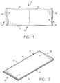
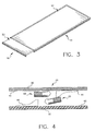
- storage phosphor cassette 10 includes an elongate rectangular shell 12 having first and second open ends 14 and 16.
- a first storage phosphor plate assembly 18 is detachably mounted in shell 12 from the first open end 14.
- a second storage phosphor plate assembly 20 is detachably mounted on shell 12 from the second open end 16.
- Each assembly 18, 20 includes a storage phosphor plate 22, 24 and a support and latching assembly 26, 28. Plates 22, 24 are butt joined or overlapped in the central region 29 of shell 12.
- Shell 12 includes upper and lower members 30, 32 and side extrusions 34, 36 which together form a rectangular shell.
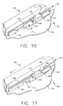
- Fig. 3 shows first storage phosphor assembly 18 partially detached from cassette 10 at a reading device (not shown).
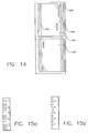
- Fig. 4 shows a cross-section of cassette 10 showing upper and lower members 30, 32 having respective opposed inner surfaces 40, 42 including deflectors 44, 46 extending therefrom for guiding the inner ends of assemblies 18, 20 to overlap. This results in an overlapping of storage phosphor plates 22 and 24 to form a composite storage phosphor plate for elongate radiographic images, such as the human spine and leg.
- Fig. 5 shows a radiographic imaging system using the elongated storage phosphor cassette of the present invention.
- cassette 10 is mounted on support 50.
- Patient 52 is positioned between cassette 10 and a source 54 of X-rays.
- An X-ray beam 56 from source 54 penetrates the torso region 58 of patient 52 to record a latent radiographic image thereof in the composite storage phosphor plates of cassette 10.
- the cassette 10 is removed and the first storage phosphor assembly placed in a reading device (described later).
- the first plate is read and the first electronic image stored.
- the cassette is removed from the reading device, inverted and the second storage phosphor assembly is placed in the reading device.
- the second storage phosphor plate is read and the second electronic image is stored.
- the two images can then be processed into a single image if so desired.
- FIGs. 6, 7 and 8 show in greater detail the components of storage phosphor cassette 10.
- cassette 10 is viewed from one end showing first storage phosphor assembly 18. It will be understood that the other end of cassette 10 is similar in structure but showing storage phosphor assembly 20.
- Storage phosphor plate assembly 18 has a storage phosphor plate 22 including an aluminum support plate 60 carrying a storage phosphor screen 62. Plate 22 is cantilevered from assembly 26 which has a plurality of openings 64 and an opening 68 to be explained later (Fig. 8).
- Shell 12 has a lower member 32 having notches 66 with set back portions 70 at each open end 14, 16. A locking mechanism in assembly 26 locks storage phosphor plate assembly 18 into shell 12.
- storage phosphor reading device 100 includes a cassette receiving station 102 for receiving a cassette 103 containing a storage phosphor plate that stores a latent radiographic image.
- Station 102 has clamps 104, 106 for clamping the end of cassette 103.
- Extractor bar assembly 108 includes hooks 110 for removing and replacing a storage phosphor assembly relative to cassette 103.
- Assembly 108 is mounted on stage 112 for movement in opposite directions 114.
- Stage 112 is mounted for movement in opposite directions 116 on rails 118, 120 on support 122.
- the lower member 130 of cassette 103 has cut-outs 132 with slots 134.
- the support and latch assembly 136 of the storage phosphor plate assembly contained in cassette 103 has a front wall 138 with openings 140 through which hooks 110 project.
- Assembly 136 has a latch 142 with cutouts 144 and angled tabs 146.
- the storage phosphor plate assembly is locked in cassette 103 by the mating of tabs 146 of latch 142 with slots 134 of cutouts 132.
- hooks 110 with bearing portion 110a of extractor bar assembly 108 have been moved to the left to unlatch latch 142 from lower member 130 of cassette 103. Hooks 110 grab front wall 138 of the storage phosphor plate assembly to allow removal of the assembly from cassette 103.
- extractor bar assembly 108 has engaged storage phosphor plate assembly 150 of cassette 103 and unlatched assembly 150 from cassette shell 152 of cassette 103.
- extractor bar assembly 108 has completely removed storage phosphor plate assembly 150 from shell 152 of cassette 103.
- Assembly 108 and assembly 150 are then moved in the direction 116 so that a laser scanner (not shown) reads the latent radiographic image stored in the storage phosphor screen 154 of storage phosphor plate assembly 150.
- U.S. Patent 5,276,333, issued January 4, 1994, inventor Robertson discloses an exemplary X-ray cassette having a single removable storage phosphor assembly.
- U.S. Patent 5,330,309, issued July 19, 1994, inventors Brahm et al. discloses an exemplary reader having cassette locating and unlatching mechanism.
- this cassette shell could have a three-sided, U shaped with an open bottom in which the storage phosphor plate assemblies close off the open bottom.
- Other type of latching mechanisms can also be used.
- elongated cassette 200 contains contiguous storage phosphor plates 202 and 204.
- x-ray transparent/opaque alignment rulers 206 and 208 (meter, inches).
- Rulers 206 and 208 have regular markings which during exposure imposes a shadow of the ruler on plates 202 and 204. The regular marking are illustrated in Fig. 15a and 15b as regularly spaced metric or inches lines or circles.
- Rulers 206 and 208 are preferably made of a metal substance such as lead of different densities or of any other x-ray translucent/opaque material or combination of materials that impose sufficient latent contrast of the ruler markings on plates 202 and 204.
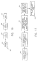
- system 220 includes x-ray exposure assembly 222( such as shown in Fig. 2); CR reader 224, image processor 226, and output 228.
- Fig. 17 shows the flow of operations of system 220.
- a shadow of the ruler is imposed as a latent image on the storage phosphor plates (box 230).
- the exposed storage phosphor plates are then scanned (box 232) using a computed radiography storage phosphor reader 224 resulting in two digital radiographic images, each containing an image of a portion of the ruler.
- the storage phosphor reader 224 will be informed, e.g., via keyboard entry by a radiographic technologist, or electronically via the radiology information system, that a composite image should be generated.
- Reference markings on the ruler are then automatically recognized from each of the digital images by the image processing software (226) using a standard pattern recognition method to determine the top and bottom images and left versus right orientation (box 234).
- the rulers also provide an indication of any missing image data that may be caused by a small physical gap between the two storage phosphor plates inside the extended length cassette. The exact amount of missing data is determined by calculating the portion of the center of the ruler that is missing from each of the sub-images.
- Both the top and bottom images are then digitally re-sampled using interpolation (such as bilinear, cubic spine etc) (box 236) to align the rulers across the two storage phosphor plates. Any residual missing pixel data in the composite image caused by a gap between top and bottom images is then filled-in using digital interpolation or using a predetermined constant pixel value.
- interpolation such as bilinear, cubic spine etc
- the final composite image is then stored, printed or displayed (box 238-output 228).
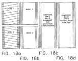
- Figs. 18a-18d are a graphical illustration of the processing steps required to automatically construct the composite image from the two seamed sub-images.
- Fig. 18a depicts each storage phosphor plate being independently scanned. The scanning direction may not be exactly aligned with the edge of the plate causing the rulers to be offset between the two images.
- Fig. 18b shows the effect on the captured image of imperfect scanning of the top and bottom storage phosphor plates.
- Fig. 18c shows realignment of the top and bottom images to the known dimensions and positions since the rulers have known truth dimensions and positional relationships between the top and bottom plates.
- Fig. 18d shows filling in any missing image data using digital interpolation to construct the final composite image.
Landscapes
- Physics & Mathematics (AREA)
- General Physics & Mathematics (AREA)
- Apparatus For Radiation Diagnosis (AREA)
- Radiography Using Non-Light Waves (AREA)
- Conversion Of X-Rays Into Visible Images (AREA)
- Measurement Of Radiation (AREA)
Applications Claiming Priority (2)
| Application Number | Priority Date | Filing Date | Title |
|---|---|---|---|
| US746759 | 2000-12-21 | ||
| US09/746,759 US6696691B2 (en) | 2000-12-21 | 2000-12-21 | Elongated computed radiography cassette having image alignment aid |
Publications (2)
| Publication Number | Publication Date |
|---|---|
| EP1220021A2 true EP1220021A2 (de) | 2002-07-03 |
| EP1220021A3 EP1220021A3 (de) | 2005-01-12 |
Family
ID=25002217
Family Applications (1)
| Application Number | Title | Priority Date | Filing Date |
|---|---|---|---|
| EP01204765A Withdrawn EP1220021A3 (de) | 2000-12-21 | 2001-12-10 | Elongierte Röntgenkassette mit Mitteln zum Aufbelichten von Referenzmarkierungen |
Country Status (3)
| Country | Link |
|---|---|
| US (1) | US6696691B2 (de) |
| EP (1) | EP1220021A3 (de) |
| JP (1) | JP2002214747A (de) |
Cited By (1)
| Publication number | Priority date | Publication date | Assignee | Title |
|---|---|---|---|---|
| EP1583996A4 (de) * | 2003-01-17 | 2006-02-08 | Steris Inc | Pad-baugruppe, die zur aufnahme einer röntgenkassette ausgelegtist und verfahren zu ihrer verwendung |
Families Citing this family (9)
| Publication number | Priority date | Publication date | Assignee | Title |
|---|---|---|---|---|
| EP1531359B1 (de) * | 2003-11-14 | 2007-07-18 | Agfa-Gevaert HealthCare GmbH | Kassette für eine Speicherleuchtstoffplatte |
| USD533472S1 (en) * | 2004-08-30 | 2006-12-12 | Sicel Technologies, Inc. | External dosimeter patch |
| JP2008517331A (ja) * | 2004-10-15 | 2008-05-22 | オレックス コンピューテッド ラジオグラフィー リミテッド | 長尺被写体x線撮像方法及び装置 |
| DE102006024242A1 (de) * | 2006-05-23 | 2007-11-29 | Siemens Ag | Verfahren zur Detektierung einer Abweichung eines Röntgensystems in Bezug auf eine Soll-Position |
| JP5137252B2 (ja) * | 2008-09-24 | 2013-02-06 | 富士フイルム株式会社 | 放射線画像撮影装置 |
| KR102105853B1 (ko) * | 2013-07-26 | 2020-05-04 | 삼성전자주식회사 | 엑스 선 스티칭 지그 |
| JP6072102B2 (ja) * | 2015-01-30 | 2017-02-01 | キヤノン株式会社 | 放射線撮影システム及び放射線撮影方法 |
| CN105832353B (zh) * | 2015-01-30 | 2020-11-06 | 佳能株式会社 | 放射线摄像系统 |
| US10368823B2 (en) * | 2015-01-30 | 2019-08-06 | Canon Kabushiki Kaisha | Radiographing apparatus, control apparatus, control method, and storage medium |
Family Cites Families (21)
| Publication number | Priority date | Publication date | Assignee | Title |
|---|---|---|---|---|
| US3725703A (en) | 1971-06-09 | 1973-04-03 | P Bucky | X-ray film cassette |
| US3774045A (en) | 1972-09-28 | 1973-11-20 | R Trott | Cart top x-ray cassette holder |
| JP2585832B2 (ja) | 1990-04-03 | 1997-02-26 | 富士写真フイルム株式会社 | 放射線画像情報記録読取装置 |
| JP2680167B2 (ja) | 1990-05-21 | 1997-11-19 | 富士写真フイルム株式会社 | 放射線画像記録読取方法およびその装置 |
| US5276333A (en) | 1991-11-27 | 1994-01-04 | Eastman Kodak Company | X-ray cassette having removable photographic element |
| US5330309A (en) * | 1992-11-25 | 1994-07-19 | Eastman Kodak Company | Reader having cassette locating and unlatching mechanism |
| EP0866342B1 (de) * | 1997-03-21 | 2005-03-23 | Agfa-Gevaert | Verfahren zur Aufzeichnung und Wiedergabe eines Strahlungsbildes von einem länglichen Körper |
| US5986279A (en) | 1997-03-21 | 1999-11-16 | Agfa-Gevaert | Method of recording and reading a radiation image of an elongate body |
| US6273606B1 (en) * | 1997-12-01 | 2001-08-14 | Agfa-Gevaert | Method and assembly for recording a radiation image of an elongate body |
| EP0919856B1 (de) | 1997-12-01 | 2005-07-06 | Agfa-Gevaert | Verfahren und Vorrichtung zur Aufzeichnung eines Strahlungsbildes von einem länglichen Körper |
| JP4076684B2 (ja) | 1998-12-15 | 2008-04-16 | 富士フイルム株式会社 | 画像合成システム |
| JP3946895B2 (ja) | 1999-02-22 | 2007-07-18 | 富士フイルム株式会社 | 蓄積性蛍光体シート用カセッテ |
| JP2000258861A (ja) | 1999-03-08 | 2000-09-22 | Fuji Photo Film Co Ltd | 蓄積性蛍光体シート及びこれを収容するカセッテ |
| JP2000267210A (ja) | 1999-03-15 | 2000-09-29 | Fuji Photo Film Co Ltd | 蓄積性蛍光体シート用カセッテ |
| JP4132373B2 (ja) | 1999-03-23 | 2008-08-13 | 富士フイルム株式会社 | 放射線画像の連結処理方法および放射線画像処理装置 |
| JP4083337B2 (ja) | 1999-03-23 | 2008-04-30 | 富士フイルム株式会社 | 放射線画像の連結処理方法および放射線画像処理装置 |
| JP4040222B2 (ja) | 1999-03-23 | 2008-01-30 | 富士フイルム株式会社 | 放射線画像の連結処理方法および放射線画像処理装置 |
| JP2000285252A (ja) | 1999-03-31 | 2000-10-13 | Fuji Photo Film Co Ltd | 画像の表示方法および表示装置、並びに画像の位置合わせ方法および位置合わせ装置 |
| JP2001202507A (ja) | 1999-06-02 | 2001-07-27 | Fuji Photo Film Co Ltd | 画像の位置合わせ処理方法および位置合わせ処理装置 |
| JP2001274974A (ja) | 2000-03-24 | 2001-10-05 | Fuji Photo Film Co Ltd | 放射線画像の連結処理方法および放射線画像処理装置 |
| JP2001307085A (ja) | 2000-04-20 | 2001-11-02 | Fuji Photo Film Co Ltd | 画像の連結処理方法および画像処理装置 |
-
2000
- 2000-12-21 US US09/746,759 patent/US6696691B2/en not_active Expired - Lifetime
-
2001
- 2001-12-04 JP JP2001370599A patent/JP2002214747A/ja active Pending
- 2001-12-10 EP EP01204765A patent/EP1220021A3/de not_active Withdrawn
Cited By (1)
| Publication number | Priority date | Publication date | Assignee | Title |
|---|---|---|---|---|
| EP1583996A4 (de) * | 2003-01-17 | 2006-02-08 | Steris Inc | Pad-baugruppe, die zur aufnahme einer röntgenkassette ausgelegtist und verfahren zu ihrer verwendung |
Also Published As
| Publication number | Publication date |
|---|---|
| US20020121612A1 (en) | 2002-09-05 |
| EP1220021A3 (de) | 2005-01-12 |
| JP2002214747A (ja) | 2002-07-31 |
| US6696691B2 (en) | 2004-02-24 |
Similar Documents
| Publication | Publication Date | Title |
|---|---|---|
| US6269177B1 (en) | Method for reconstructing radiation image of a body from partial radiation images | |
| US6273606B1 (en) | Method and assembly for recording a radiation image of an elongate body | |
| EP1231484B1 (de) | Verfahren zum Wiederaufbau des Strahlungsbildes aus Strahlungsteilbildern | |
| US5865745A (en) | Remote health care information input apparatus | |
| US20060171507A1 (en) | Radiographic apparatus | |
| JPH05506177A (ja) | 電子計算機処理放射線写真患者識別システム | |
| US6696691B2 (en) | Elongated computed radiography cassette having image alignment aid | |
| JP2000037374A (ja) | 放射線撮影装置 | |
| EP0919858B1 (de) | Verfahren zum Zusammensetzen des Strahlungsbildes eines Körpers aus Strahlungsteilbildern | |
| JP3788510B2 (ja) | 医用画像装置及び該装置における表示画面の遷移方法並びに画面遷移プログラム | |
| JP2000258861A (ja) | 蓄積性蛍光体シート及びこれを収容するカセッテ | |
| JP2004321479A (ja) | 乳房画像撮影システム及び情報管理方法 | |
| Artz | Computed radiography for the radiological technologist | |
| US7479648B2 (en) | Methods and apparatus for imaging elongate objects | |
| US6852987B2 (en) | Elongated computed radiography cassette | |
| JP2000250153A (ja) | 蓄積性蛍光体シート用カセッテ | |
| US6843598B2 (en) | Imaging plate cassette for extended X-ray photographs | |
| EP0599098A2 (de) | Mehrere Versionen eines Speicherleuchtstoffbildes | |
| JP3946895B2 (ja) | 蓄積性蛍光体シート用カセッテ | |
| JP2000037382A (ja) | ブッキー撮影台 | |
| EP0741371A1 (de) | Verfahren zur Wiedergabe eines Strahlungsbildes | |
| US20040073628A1 (en) | Medical image photographing management terminal and medical image photographing system | |
| Jafroudi et al. | Quality control on storage phosphor digital radiography system | |
| JP2727248B2 (ja) | 画像読取装置 | |
| JP2779551B2 (ja) | 医用画像再生システム |
Legal Events
| Date | Code | Title | Description |
|---|---|---|---|
| PUAI | Public reference made under article 153(3) epc to a published international application that has entered the european phase |
Free format text: ORIGINAL CODE: 0009012 |
|
| AK | Designated contracting states |
Kind code of ref document: A2 Designated state(s): AT BE CH CY DE DK ES FI FR GB GR IE IT LI LU MC NL PT SE TR |
|
| AX | Request for extension of the european patent |
Free format text: AL;LT;LV;MK;RO;SI |
|
| PUAL | Search report despatched |
Free format text: ORIGINAL CODE: 0009013 |
|
| AK | Designated contracting states |
Kind code of ref document: A3 Designated state(s): AT BE CH CY DE DK ES FI FR GB GR IE IT LI LU MC NL PT SE TR |
|
| AX | Request for extension of the european patent |
Extension state: AL LT LV MK RO SI |
|
| RIC1 | Information provided on ipc code assigned before grant |
Ipc: 7G 01T 1/29 B Ipc: 7G 03B 42/04 A |
|
| 17P | Request for examination filed |
Effective date: 20050613 |
|
| AKX | Designation fees paid |
Designated state(s): DE FR GB |
|
| STAA | Information on the status of an ep patent application or granted ep patent |
Free format text: STATUS: THE APPLICATION IS DEEMED TO BE WITHDRAWN |
|
| 18D | Application deemed to be withdrawn |
Effective date: 20060419 |