EP1220046A2 - Dispositif de formation d'images et dispositif d'empilage de feuilles éjectées pour celui-ci - Google Patents
Dispositif de formation d'images et dispositif d'empilage de feuilles éjectées pour celui-ci Download PDFInfo
- Publication number
- EP1220046A2 EP1220046A2 EP01310357A EP01310357A EP1220046A2 EP 1220046 A2 EP1220046 A2 EP 1220046A2 EP 01310357 A EP01310357 A EP 01310357A EP 01310357 A EP01310357 A EP 01310357A EP 1220046 A2 EP1220046 A2 EP 1220046A2
- Authority
- EP
- European Patent Office
- Prior art keywords
- sheet
- ejected
- stacking device
- image forming
- forming apparatus
- Prior art date
- Legal status (The legal status is an assumption and is not a legal conclusion. Google has not performed a legal analysis and makes no representation as to the accuracy of the status listed.)
- Granted
Links
- 230000007246 mechanism Effects 0.000 claims abstract description 72
- 238000000638 solvent extraction Methods 0.000 claims description 10
- 108091008695 photoreceptors Proteins 0.000 description 12
- 238000000034 method Methods 0.000 description 11
- 230000001681 protective effect Effects 0.000 description 11
- 230000015572 biosynthetic process Effects 0.000 description 7
- 238000005520 cutting process Methods 0.000 description 6
- 230000008569 process Effects 0.000 description 6
- 238000004519 manufacturing process Methods 0.000 description 5
- 238000009434 installation Methods 0.000 description 4
- 230000037361 pathway Effects 0.000 description 2
- 238000004140 cleaning Methods 0.000 description 1
- 230000008878 coupling Effects 0.000 description 1
- 238000010168 coupling process Methods 0.000 description 1
- 238000005859 coupling reaction Methods 0.000 description 1
- 239000000463 material Substances 0.000 description 1
- 238000012986 modification Methods 0.000 description 1
- 230000004048 modification Effects 0.000 description 1
- 239000002245 particle Substances 0.000 description 1
- 238000005192 partition Methods 0.000 description 1
- 230000009467 reduction Effects 0.000 description 1
Images


Classifications
-
- G—PHYSICS
- G03—PHOTOGRAPHY; CINEMATOGRAPHY; ANALOGOUS TECHNIQUES USING WAVES OTHER THAN OPTICAL WAVES; ELECTROGRAPHY; HOLOGRAPHY
- G03G—ELECTROGRAPHY; ELECTROPHOTOGRAPHY; MAGNETOGRAPHY
- G03G15/00—Apparatus for electrographic processes using a charge pattern
- G03G15/65—Apparatus which relate to the handling of copy material
- G03G15/6552—Means for discharging uncollated sheet copy material, e.g. discharging rollers, exit trays
-
- B—PERFORMING OPERATIONS; TRANSPORTING
- B65—CONVEYING; PACKING; STORING; HANDLING THIN OR FILAMENTARY MATERIAL
- B65H—HANDLING THIN OR FILAMENTARY MATERIAL, e.g. SHEETS, WEBS, CABLES
- B65H31/00—Pile receivers
- B65H31/22—Pile receivers removable or interchangeable
-
- B—PERFORMING OPERATIONS; TRANSPORTING
- B65—CONVEYING; PACKING; STORING; HANDLING THIN OR FILAMENTARY MATERIAL
- B65H—HANDLING THIN OR FILAMENTARY MATERIAL, e.g. SHEETS, WEBS, CABLES
- B65H31/00—Pile receivers
- B65H31/24—Pile receivers multiple or compartmented, e.d. for alternate, programmed, or selective filling
-
- B—PERFORMING OPERATIONS; TRANSPORTING
- B65—CONVEYING; PACKING; STORING; HANDLING THIN OR FILAMENTARY MATERIAL
- B65H—HANDLING THIN OR FILAMENTARY MATERIAL, e.g. SHEETS, WEBS, CABLES
- B65H2408/00—Specific machines
- B65H2408/10—Specific machines for handling sheet(s)
- B65H2408/11—Sorters or machines for sorting articles
- B65H2408/111—Sorters or machines for sorting articles with stationary location in space of the bins and a diverter per bin
-
- G—PHYSICS
- G03—PHOTOGRAPHY; CINEMATOGRAPHY; ANALOGOUS TECHNIQUES USING WAVES OTHER THAN OPTICAL WAVES; ELECTROGRAPHY; HOLOGRAPHY
- G03G—ELECTROGRAPHY; ELECTROPHOTOGRAPHY; MAGNETOGRAPHY
- G03G2215/00—Apparatus for electrophotographic processes
- G03G2215/00362—Apparatus for electrophotographic processes relating to the copy medium handling
- G03G2215/00886—Sorting or discharging
- G03G2215/0089—Shifting jobs
Definitions
- This invention relates to an image forming apparatus and an ejected sheet stacking device which is selectively used in this image forming apparatus.
- a multi-function machine that is, an image forming apparatus having a copying function, a facsimile function, and a printer function is broadly utilized.
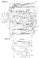
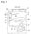
- FIG. 6 is an illustration showing in broad outline an example of the structure of an image forming apparatus employing a conventional inner tray method as seen from the front direction.
- This image forming apparatus 60 has a sheet ejection part 63 formed in a hollow place 62 which is formed in such a manner as to open to the outside through the front surface (the surface parallel to the paper surface in the drawing) of the outer housing 61 and through the one side surface (the right-hand side surface in the drawing), and in this sheet ejection part 63, a sheet storing mechanism 63A for storing sheets ejected from a sheet ejection opening is provided.
- an image formation part 65 for practicing image formation on the basis of original image information which has been read by a document scanning part 64, and a paper feed unit 66 storing sheets to be fed to this image formation part 65, in the state that they are arrayed in the up-and-down direction.
- 67 denotes a conveyance part for conveying sheets such as plain paper sheets for example
- 68 denotes a fixing part for fixing a toner image formed on a sheet.
- a sheet having a visible image formed in the image formation part 65 is conveyed by the conveyance part 67 in the horizontal direction under the hollow place 62, and is subjected to fixing processing in a fixing part 68; then, it is conveyed upward through an upward-extending conveyance path 70, and is ejected from the sheet ejection opening by ejection rollers 71, to be contained in the sheet storing mechanism 63A.
- an apparatus having a structure with its large height size to secure the hollow place 62 of a sufficient size, and being provided with a reception and print sheet storing part 69A composed of a sheet storing mechanism, a tray for example, for storing sheets ejected during the use of the facsimile or printer function, and a copy sheet storing part 69B which is a sheet storing mechanism for storing sheets ejected during the use of the copying function.
- the sheet conveyance path 70 in this image forming apparatus 60A has a bifurcation path 70A leading to the reception and print sheet storing part 69A and a bifurcation path 70B leading to the copied sheet storing part 69B, and a switching guide 72 is provided at the bifurcation point.
- This invention has been made on the basis of the above-mentioned things, and it is its object to provide an image forming apparatus whose function a user can freely intend to diversify.
- auxiliary tray which is capable of being inserted and drawn out in the direction of entering sheets.
- an ejected sheet stacking device of this invention is mounted through an opening for mounting which is formed in the inner wall partitioning a hollow place of an image forming apparatus so as to expose the portion to be connected to the ejected sheet stacking device, and is provided with a holding portion for holding a cover member for stopping said opening for mounting which is left behind after said ejected sheet stacking device is dismounted from the image forming apparatus.
- an image forming apparatus having the above-mentioned structure (1), because an ejected sheet stacking device provided with a plurality of sheet storing trays and a switching mechanism can be alternatively mounted instead of a sheet storing mechanism, a user can intend to diversify the function of the image forming apparatus freely as the occasion demands.
- an ejecting and conveying mechanism, a bifurcating conveyance path, and a switching mechanism are provided in the ejected sheet stacking device to be mounted, it is unnecessary to provide component parts for sorting processing in the mainframe of the image forming apparatus, and the manufacturing cost can be reduced by this, which makes the apparatus useful also for a user who does not need a sorting function.
- the hollow place formed in the outer housing has a first space portion and a second space portion whose bottom surface level is lower than that of the first space portion
- the distance between the sheet storing trays can be made large, which makes it possible to raise the sheet storing capacity of each sheet storing trays, and also makes it possible to take out the contained sheets easily.
- a second-stage ejected sheet stacking device in a state where a first-stage ejected sheet stacking device is mounted in the hollow place, a second-stage ejected sheet stacking device can be further mounted; therefore, the number of sheet storing trays can be increased as the occasion demands, and on top of it, because the second-stage ejected sheet stacking device can be mounted substantially in the hollow place, the occupied area for installation never becomes broader by a large margin.
- connection part for the ejected sheet stacking device is covered with a protective cover portion of the inner wall partitioning the hollow place; therefore, said connection part is protected, and in the case where an ejected sheet stacking device is mounted, because the connection part is exposed through the formation of an opening for mounting by cutting off the protective cover portion, only it is necessary to connect the ejected sheet stacking device through inserting it into the hollow place, which makes it possible to mount the device very easily.
- Fig. 1 is a cross-sectional view as seen from the front direction showing in broad outline an example of practice of an image forming apparatus of this invention.
- This image forming apparatus 10 is one employing what is called a inner tray method; to state it concretely, a sheet ejection part 12 is formed in a hollow place 20 formed in such a manner as to open to the outside through the front surface (the surface parallel to the paper surface in the drawing) of the outer housing 11 and through one of the side surfaces (left side surface in the drawing), and in this sheet ejection part 12, a sheet storing mechanism 12A consisting of a single tray is mounted in such a manner as to be able to be mounted and dismounted.
- a document image reading part 13 for reading an original image through optically scanning a document to obtain image data is arranged above the hollow place 20, while under the hollow place 20, there are arranged an image writing part 14 for forming an electrostatic latent image on a drum-shaped photoreceptor 15A in an image forming part 15 on the basis of image data from the document image reading part 13, the image forming part 15, which is positioned at the other side part of the outer housing 11 in such a manner as to come in line with this image writing part 14 in the horizontal direction, for making visible the electrostatic latent image on the photoreceptor 15A, and a paper feed unit 16 positioned under the image writing part 14 for storing sheets as image recording materials.
- 17 denotes an automatic document feeding mechanism provided on the upper surface of the outer housing 11
- 18 denotes an inversion conveyance mechanism, which is one for conveying a sheet having a visible image formed on its one side again to the image forming part 15 with the other side made to face left.
- the image forming part 15 is composed of the drum-shaped photoreceptor 15A, a charging part 15B for charging said photoreceptor 15A, a developing device 15C for forming a toner image by making the electrostatic latent image formed on the photoreceptor 15A a visible image, a transfer part 15D for transferring the toner image formed on the photoreceptor 15A to a sheet, a detaching part 15E for detaching the sheet closely adhering to the photoreceptor 15A, a fixing part 15F for fixing the toner image transferred to the sheet, and a cleaning part 15G for removing the toner particles remaining on the surface of the photoreceptor 15A, and has a structure such that a sheet leaving the paper feed unit 16 is conveyed upward.
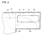
- the hollow place 20 comprises a first space portion 20A succeeding to the sheet ejection opening 22 and a second space portion 20B which is partitioned by a partitioning line L shown by the single dot and dash line in the drawing and succeeds to the first space portion 20A in such a manner as to be positioned side by side with it to the sheet ejecting direction (the left direction in the drawing), and the bottom surface level of the second space portion 20B is made lower than that of the first space portion.
- the difference of the bottom surface levels between the first space portion 20A and the second space portion 20B is 50 mm or over, for example.
- a protective cover portion 231 for covering a connection part composed of a driving force transmitting portion and a drive control system for supplying a driving force to the ejected sheet stacking device.
- an electrostatic latent image is formed on the photoreceptor 15A by the image writing part 15B on the basis of this original image information, and by making visible this electrostatic latent image by the developing device 15C, a toner image is formed on the surface of the photoreceptor 15A.
- the transfer part 15D the toner image is transferred to a sheet having been conveyed from the paper feed unit 16, and after the sheet which is in a state of closely adhering to the photoreceptor 15A is detached from the photoreceptor 15A in the detaching part 15E, the sheet is conveyed to the fixing part 15F where it is subjected to fixing processing; after that, the sheet is ejected by the ejection rollers 22A from the ejection opening 22, and is contained in the sheet storing mechanism 12A.
- the above-mentioned image forming apparatus it is employed a structure such that it can be mounted an ejected sheet stacking device provided with a plurality of sheet storing trays and a switching mechanism alternatively for the sheet storing mechanism 12A consisting of a single sheet storing tray provided in the sheet ejection part 12, that is, instead of the sheet storing mechanism 12A.
- Fig. 3 is a cross-sectional view for explanation showing a state where an ejected sheet stacking device is mounted instead of a sheet storing mechanism in the image forming apparatus shown in Fig. 1.
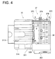
- the ejected sheet stacking device 30 to be mounted instead of the sheet storing mechanism 12A is composed of a sheet placing portion 301 consisting of a sheet storing trays 31A and 31B, which are arranged in a multi-stage way, two-stage for example, in the vertical direction and a sheet ejection-conveying portion 302, and the sheet ejection-conveying portion 302 is provided with an ejecting and conveying mechanism 32 for conveying a sheet from the sheet ejection opening 22 in the mainframe of the image forming apparatus 10 to the sheet storing tray, and a conveyance path switching mechanism 34 for switching the conveyance pathway between the bifurcation conveyance paths leading to the respective sheet storing trays 31A and 31B from the sheet ejection opening 22. Further, the sheet ejection-conveying portion 302 of the ejected sheet stacking device 30 is disposed in the first space portion 20A in the hollow place 20, while sheet placing portion 301 is disposed in the second space portion 20B in the hollow place 20.
- the ejecting and conveying mechanism 32 is provided with a plurality of pairs of the ejection-conveying rollers which consist of a group of pinch rollers (32B in Fig. 4) provided at a plurality of positions separated from one another in the width direction of sheets to be conveyed.
- a sensor 35 for detecting that the leading edge of a sheet have passed is provided, while in the sheet storing trays 31A and 31B, ejection sensors 36A and 36B for detecting that a sheet is ejected are provided respectively.
- the conveyance path switching mechanism 34 is composed of a bifurcation guide 34A and a solenoid (not shown in the drawing) which is a drive means for driving this bifurcation guide 34A, and by the bifurcation guide 34A being driven, the switching of the pathway to be used is carried out between the bifurcation path 33A leading to the upper sheet storing tray 31A and the bifurcation path 33B leading to the lower sheet storing tray 31B.
- auxiliary tray 31'A supported by a supporting rail extending in the direction of entering sheet (horizontal direction in Fig. 3) in such a manner as to be able to project and retract, and in accordance with the size of sheets to be contained, the size of the sheet placing portion 301 can be adjusted by drawing out the auxiliary tray in the direction of entering sheet.
- the same structure is employed.
- connection part 37 to be connected to the connection part of the image forming apparatus; to state it concretely, there are provided a connector portion 37A to be connected to the drive control system in the connection part of the image forming apparatus 10, a drive means 37B consisting of, for example, a coupling gear to be connected to the driving force transmitting portion of the connection part of the image forming apparatus 10, and two pin members for determining the position of projection from the rear side of the sheet ejection-conveying portion 302 toward the outside (upper direction).
- a cover member holding portion for holding a cover member for stopping the opening for mounting formed in the hollow place 20 of the image forming apparatus 10, and in this holding portion, a cover member 38 is provided fixedly with a fixing member such as a screw for example.
- cover member 38 is dismounted from the ejected sheet stacking device 30 and is used in the case where said ejected sheet stacking device is dismounted for some reasons, for example, in the case where a large-sized after-processing apparatus is attached instead of it, in the case where the previously attached sheet storing mechanism 12A is again used instead of it, or in the other like cases.
- the control program for switching the sheet storing tray between the trays 31A and 31B for every image formation process is practiced. Further, when it has been detected by the entrance sensor 35 that the leading edge of a sheet from the sheet ejection opening 22 of the mainframe of the image forming apparatus 10 has passed, the bifurcation guide 34A in the conveyance path switching mechanism 34 is driven, to select either one or the other of the bifurcation conveyance paths, and the sheet is ejected by the ejection-conveying rollers 32, to be contained in the predetermined sheet storing tray.
- sheets in each of image formation processes for example, copy sheets ejected during the use of the copying function and reception and print sheets ejected during the use of the facsimile function etc. can be contained in the respective sheet storing trays without the mixed presence of the both kinds of sheets.
- a second-stage ejected sheet stacking device having the same basic structure as the first-stage ejected sheet stacking device can be mounted.
- the second-stage ejected sheet stacking device 40 is arranged in the state where it is contained substantially in the hollow place 20 of the image forming apparatus, to state it concretely, in the state where the sheet ejection-conveying portion 402 of the second-stage ejected sheet stacking device 40 is disposed in the second space portion 20B in the hollow place 20, and the sheet placing portion 401, which consists of a plurality of sheet storing trays 41A and 41B arranged vertically in a multi-stage way, projects out of the hollow place 20.
- the image forming apparatus 10 By employing the image forming apparatus 10 as stated in the above, because it is possible to mount in it the ejected sheet stacking device 30 having the plural sheet storing trays 31A and 31B and the conveyance path switching mechanism 34 instead of the single sheet storing mechanism 12A, a user himself can intend to diversify the function of the image forming apparatus 10 freely as the occasion demands.
- the ejected sheet stacking device 30 to be mounted is provided with the ejecting and conveying mechanism 32, the bifurcation conveyance paths 33A and 33B, and the conveyance path switching mechanism 34, it is unnecessary to provide component parts for sorting processing in the mainframe of the image forming apparatus 10, which makes it possible to reduce the manufacturing cost; thus, this invention can be useful also for a user who does not need a sorting function.
- the ejected sheet stacking device having the plural sheet storing trays 31A and 31B and the conveyance path switching mechanism 34 is mounted instead of the single sheet storing mechanism 12A, as the result that two sheet storing trays are used under the condition of switching control, for example, copy sheets ejected during the use of the copying function, and the reception and print sheets ejected during the use of the facsimile function etc. can be contained certainly in the different sheet storing trays 31A and 31B respectively, without the mixed presence of the two kinds of sheets, which makes it possible to improve the productivity and the convenience.
- the image forming part 15 is arranged at the other side (right-hand side in the drawing) opposite to the one side where the opening 11A is formed, in a state where sheets are to be conveyed upward, it is possible to form the hollow place 20 in a multi-stage way having the first space portion and the second space portion with their bottom surface levels made different to each other.
- the ejected sheet stacking device 30 by mounting the ejected sheet stacking device 30 in such a way as to make the sheet placing portion 301, which is composed of the plural sheet storing trays 31A and 31B arranged in a multi-stage way, positioned in the second space portion 20B having a broader space domain, the distance between the sheet storing trays 31A and 31B can be made broader, which makes it possible to raise the sheet storing capacity of each of the sheet storing trays 31A and 31B, and also makes it possible to easily take out the sheets contained.
- the second-stage ejected sheet stacking device 40 in the state where the first-stage ejected sheet stacking device 30 is mounted in the hollow place 20, it is possible to mount the second-stage ejected sheet stacking device 40 further, succeeding to the bifurcation conveyance path 33B in the first-stage ejected sheet stacking device 30; therefore, it is possible to increase the number of the sheet storing trays that can be used alternatively by switching, and on top of it, because the second-stage ejected sheet stacking device can be contained substantially in the hollow place 20, the occupied area for installation is never made broader by a large margin.
- connection part for the ejected sheet stacking device 30 is covered with the protective cover portion 231 of the inner wall 23 partitioning the hollow place 20, said connection part is protected, and in the case where the ejected sheet stacking device is mounted, the opening for mounting is formed to expose the connection part by cutting off the protective cover portion 231; therefore, only it is necessary to insert the ejected sheet stacking device into the hollow place 20 from the front side to connect it with the connection part, which makes it possible to mount the device extremely easily.
- the cover member 38 for stopping the opening for mounting formed in the hollow place 20 is provided in the cover member holding portion of the ejected sheet stacking device 30, when the ejected sheet stacking device 30 that has once been mounted is dismounted for some reasons of a user, the cover member 38 is prevented from being lost, which makes it possible to protect the connection part certainly.
- the lead wires connected to the entrance sensor 35 and the ejection sensors 36A and 36B, and the sensors themselves can be protected by said cover member 38, while also it is possible to make the cover member function as the handle of the ejected sheet stacking device 30.
- an image forming apparatus of this invention By employing an image forming apparatus of this invention, because an ejected sheet stacking device having a plurality of sheet storing trays and a switching mechanism can be mounted alternatively instead of a sheet storing mechanism, a user himself can intend to diversify the function of the image forming apparatus freely as the occasion demands.
- an ejected sheet stacking device to be mounted is provided with an ejecting and conveying mechanism, bifurcation paths, and a switching mechanism, it is unnecessary to provide component parts for sorting processing in the mainframe of the image forming apparatus, which makes it possible to reduce the manufacturing cost, and this invention can be useful also for a user who does not need a sorting function.
- the hollow place formed in the outer housing comprises a first space portion and a second space portion having the level of the bottom surface lower than that of the first space portion
- the distance between the sheet storing trays can be made broader, which makes it possible to raise the sheet storing capacity of each of the sheet storing trays, and also makes it possible to easily take out the sheets contained.
- a second-stage ejected sheet stacking device in the state where a first-stage ejected sheet stacking device is mounted in the hollow place, a second-stage ejected sheet stacking device can be mounted further; therefore, it is possible to increase the number of the sheet storing trays as the occasion demands, and on top of it, the second-stage ejected sheet stacking device can be mounted substantially in the hollow place; therefore, the occupied area for installation is never made broader by a large margin.
- an image forming apparatus of this invention By employing an image forming apparatus of this invention, in the case where an ejected sheet stacking device is mounted, because the opening for mounting is formed to expose the connection part by cutting off the protective cover portion of the inner wall partitioning the hollow place, only it is necessary to insert the ejected sheet stacking device into the hollow place to connect it with this connection part, which makes it possible to mount the device extremely easily.
- an ejected sheet stacking device of this invention because it is provided with an ejecting and conveying mechanism, bifurcation paths, and a switching mechanism, for example, copy sheets ejected during the use of the copying function and reception and print sheets ejected during the use of the facsimile function etc. can be certainly contained in the different sheet storing trays respectively without the mixed presence of the both kinds of sheets, and on top of it, it is unnecessary to provide particular component parts for sorting processing in the mainframe of an image forming apparatus, which makes it possible to make the image forming apparatus mainframe small-sized, and also makes it possible to reduce the manufacturing cost.
Landscapes
- Engineering & Computer Science (AREA)
- Mechanical Engineering (AREA)
- Physics & Mathematics (AREA)
- General Physics & Mathematics (AREA)
- Pile Receivers (AREA)
- Paper Feeding For Electrophotography (AREA)
- Delivering By Means Of Belts And Rollers (AREA)
- Separation, Sorting, Adjustment, Or Bending Of Sheets To Be Conveyed (AREA)
- Facsimiles In General (AREA)
Applications Claiming Priority (2)
| Application Number | Priority Date | Filing Date | Title |
|---|---|---|---|
| JP2000395783 | 2000-12-26 | ||
| JP2000395783A JP3888056B2 (ja) | 2000-12-26 | 2000-12-26 | 画像形成装置および排出シート積載装置 |
Publications (3)
| Publication Number | Publication Date |
|---|---|
| EP1220046A2 true EP1220046A2 (fr) | 2002-07-03 |
| EP1220046A3 EP1220046A3 (fr) | 2006-03-01 |
| EP1220046B1 EP1220046B1 (fr) | 2009-09-30 |
Family
ID=18861186
Family Applications (1)
| Application Number | Title | Priority Date | Filing Date |
|---|---|---|---|
| EP01310357A Expired - Lifetime EP1220046B1 (fr) | 2000-12-26 | 2001-12-11 | Dispositif de formation d'images et dispositif d'empilage de feuilles éjectées pour celui-ci |
Country Status (4)
| Country | Link |
|---|---|
| US (1) | US6542715B2 (fr) |
| EP (1) | EP1220046B1 (fr) |
| JP (1) | JP3888056B2 (fr) |
| DE (1) | DE60140038D1 (fr) |
Families Citing this family (16)
| Publication number | Priority date | Publication date | Assignee | Title |
|---|---|---|---|---|
| US6941079B1 (en) | 2001-05-24 | 2005-09-06 | Cisco Technology, Inc. | Optical demultiplexer with multi-channel power control and tilt compensation |
| JP3986884B2 (ja) * | 2002-05-14 | 2007-10-03 | キヤノンファインテック株式会社 | 原稿給送装置及びこれを備えた画像形成装置 |
| JP2004215178A (ja) * | 2003-01-08 | 2004-07-29 | Brother Ind Ltd | 画像読取装置、および、画像読取領域設定方法 |
| EP1588972B1 (fr) * | 2004-04-19 | 2013-02-27 | Canon Finetech Inc. | Organe de séparation de feuilles et appareil d'alimentation de feuilles |
| JP2006001049A (ja) * | 2004-06-15 | 2006-01-05 | Fuji Photo Film Co Ltd | 画像記録装置 |
| JP2006085085A (ja) * | 2004-09-17 | 2006-03-30 | Fuji Xerox Co Ltd | 画像形成装置 |
| JP4580750B2 (ja) * | 2004-12-20 | 2010-11-17 | シャープ株式会社 | 画像形成装置 |
| JP4039431B2 (ja) * | 2005-03-08 | 2008-01-30 | コニカミノルタビジネステクノロジーズ株式会社 | 画像形成システム |
| JP4897656B2 (ja) * | 2007-12-10 | 2012-03-14 | 株式会社リコー | 画像形成装置 |
| US8600288B2 (en) * | 2007-12-25 | 2013-12-03 | Ricoh Company, Ltd. | Image forming apparatus |
| US20100196073A1 (en) * | 2009-02-05 | 2010-08-05 | Kabushiki Kaisha Toshiba | Sheet conveying apparatus and image forming apparatus |
| DE102012214629A1 (de) * | 2012-08-17 | 2014-02-20 | Bielomatik Leuze Gmbh + Co. Kg | Vorrichtung zum Schuppen und Ablegen von Bögen auf einen Stapel |
| JP5983253B2 (ja) * | 2012-09-28 | 2016-08-31 | ブラザー工業株式会社 | 画像形成装置 |
| JP6395436B2 (ja) * | 2014-05-16 | 2018-09-26 | キヤノン株式会社 | 画像形成装置及び収容装置 |
| JP7463857B2 (ja) * | 2020-06-05 | 2024-04-09 | 京セラドキュメントソリューションズ株式会社 | 仕分け装置およびそれを備えた画像形成装置 |
| JP2026050229A (ja) * | 2024-09-09 | 2026-03-19 | 富士フイルムビジネスイノベーション株式会社 | 排出装置、画像形成装置 |
Citations (3)
| Publication number | Priority date | Publication date | Assignee | Title |
|---|---|---|---|---|
| JPH09142716A (ja) | 1995-11-21 | 1997-06-03 | Ricoh Co Ltd | 画像形成装置 |
| JPH1032661A (ja) | 1996-07-15 | 1998-02-03 | Ricoh Co Ltd | デジタル画像形成装置 |
| JPH1165195A (ja) | 1997-08-19 | 1999-03-05 | Ricoh Co Ltd | 画像形成装置 |
Family Cites Families (5)
| Publication number | Priority date | Publication date | Assignee | Title |
|---|---|---|---|---|
| JPH0439259A (ja) * | 1990-05-31 | 1992-02-10 | Mita Ind Co Ltd | スライド式排紙トレイ |
| JPH0818766B2 (ja) * | 1990-11-26 | 1996-02-28 | 三田工業株式会社 | 画像形成装置 |
| JPH08123119A (ja) * | 1994-10-19 | 1996-05-17 | Ricoh Co Ltd | 画像形成装置 |
| US6393232B1 (en) * | 1999-07-30 | 2002-05-21 | Canon Kabushiki Kaisha | Image forming apparatus capable of selecting discharge means according to material selection |
| US6381442B1 (en) * | 2000-01-31 | 2002-04-30 | Sharp Kabushiki Kaisa | Image forming apparatus with paper post-treatment device |
-
2000
- 2000-12-26 JP JP2000395783A patent/JP3888056B2/ja not_active Expired - Fee Related
-
2001
- 2001-12-11 EP EP01310357A patent/EP1220046B1/fr not_active Expired - Lifetime
- 2001-12-11 DE DE60140038T patent/DE60140038D1/de not_active Expired - Lifetime
- 2001-12-17 US US10/023,956 patent/US6542715B2/en not_active Expired - Lifetime
Patent Citations (3)
| Publication number | Priority date | Publication date | Assignee | Title |
|---|---|---|---|---|
| JPH09142716A (ja) | 1995-11-21 | 1997-06-03 | Ricoh Co Ltd | 画像形成装置 |
| JPH1032661A (ja) | 1996-07-15 | 1998-02-03 | Ricoh Co Ltd | デジタル画像形成装置 |
| JPH1165195A (ja) | 1997-08-19 | 1999-03-05 | Ricoh Co Ltd | 画像形成装置 |
Also Published As
| Publication number | Publication date |
|---|---|
| JP3888056B2 (ja) | 2007-02-28 |
| US6542715B2 (en) | 2003-04-01 |
| JP2002193532A (ja) | 2002-07-10 |
| EP1220046A3 (fr) | 2006-03-01 |
| EP1220046B1 (fr) | 2009-09-30 |
| DE60140038D1 (de) | 2009-11-12 |
| US20020081134A1 (en) | 2002-06-27 |
Similar Documents
| Publication | Publication Date | Title |
|---|---|---|
| US6542715B2 (en) | Image forming apparatus and ejected sheet stacking device for use therewith | |
| EP2071409B1 (fr) | Appareil de formation d'images et procédé de contrôle de transport de feuille utilisé avec celui-ci | |
| USRE39168E1 (en) | Image forming apparatus in use with a sheet post-processing apparatus | |
| JPH04350062A (ja) | 画像形成装置及びその制御装置 | |
| JP2002318477A (ja) | 画像形成装置 | |
| US20050231772A1 (en) | Image forming apparatus | |
| JP3690103B2 (ja) | 記録媒体排出装置 | |
| KR100338620B1 (ko) | 용지 적재 장치 및 용지 적재 장치를 갖는 화상 형성 장치 | |
| JP3639098B2 (ja) | 用紙積載装置 | |
| JPH11236166A (ja) | 記録媒体排出装置 | |
| US12595148B2 (en) | Sheet conveying device and image forming apparatus | |
| US4952981A (en) | Toner image printing apparatus | |
| JP2006313225A (ja) | 画像形成装置 | |
| JPH04213530A (ja) | 画像形成装置 | |
| EP2068200B1 (fr) | Système de formation d'images | |
| JP3559780B2 (ja) | シート処理装置及び画像形成装置 | |
| JPH0342436A (ja) | シート給送装置のシート収納カセット | |
| JPH07315668A (ja) | 画像形成装置の用紙排出装置 | |
| JP3785786B2 (ja) | 記録媒体排出装置 | |
| JPH05162413A (ja) | 画像形成装置の組立方法 | |
| JP4091155B2 (ja) | 画像形成装置 | |
| JP3436649B2 (ja) | シート後処理装置を備えた画像形成装置 | |
| JPH0551836U (ja) | 画像形成装置 | |
| JPH07112899B2 (ja) | 中間トレイを有する画像形成装置の給紙制御方法 | |
| JPH1141390A (ja) | ファクシミリ装置 |
Legal Events
| Date | Code | Title | Description |
|---|---|---|---|
| PUAI | Public reference made under article 153(3) epc to a published international application that has entered the european phase |
Free format text: ORIGINAL CODE: 0009012 |
|
| AK | Designated contracting states |
Kind code of ref document: A2 Designated state(s): AT BE CH CY DE DK ES FI FR GB GR IE IT LI LU MC NL PT SE TR |
|
| AX | Request for extension of the european patent |
Free format text: AL;LT;LV;MK;RO;SI |
|
| PUAL | Search report despatched |
Free format text: ORIGINAL CODE: 0009013 |
|
| AK | Designated contracting states |
Kind code of ref document: A3 Designated state(s): AT BE CH CY DE DK ES FI FR GB GR IE IT LI LU MC NL PT SE TR |
|
| AX | Request for extension of the european patent |
Extension state: AL LT LV MK RO SI |
|
| 17P | Request for examination filed |
Effective date: 20060807 |
|
| AKX | Designation fees paid |
Designated state(s): DE FR GB |
|
| 17Q | First examination report despatched |
Effective date: 20070427 |
|
| GRAP | Despatch of communication of intention to grant a patent |
Free format text: ORIGINAL CODE: EPIDOSNIGR1 |
|
| GRAS | Grant fee paid |
Free format text: ORIGINAL CODE: EPIDOSNIGR3 |
|
| GRAA | (expected) grant |
Free format text: ORIGINAL CODE: 0009210 |
|
| AK | Designated contracting states |
Kind code of ref document: B1 Designated state(s): DE FR GB |
|
| REG | Reference to a national code |
Ref country code: GB Ref legal event code: FG4D |
|
| REF | Corresponds to: |
Ref document number: 60140038 Country of ref document: DE Date of ref document: 20091112 Kind code of ref document: P |
|
| PLBE | No opposition filed within time limit |
Free format text: ORIGINAL CODE: 0009261 |
|
| STAA | Information on the status of an ep patent application or granted ep patent |
Free format text: STATUS: NO OPPOSITION FILED WITHIN TIME LIMIT |
|
| 26N | No opposition filed |
Effective date: 20100701 |
|
| PGFP | Annual fee paid to national office [announced via postgrant information from national office to epo] |
Ref country code: DE Payment date: 20141202 Year of fee payment: 14 Ref country code: GB Payment date: 20141210 Year of fee payment: 14 |
|
| PGFP | Annual fee paid to national office [announced via postgrant information from national office to epo] |
Ref country code: FR Payment date: 20141208 Year of fee payment: 14 |
|
| REG | Reference to a national code |
Ref country code: DE Ref legal event code: R119 Ref document number: 60140038 Country of ref document: DE |
|
| GBPC | Gb: european patent ceased through non-payment of renewal fee |
Effective date: 20151211 |
|
| REG | Reference to a national code |
Ref country code: FR Ref legal event code: ST Effective date: 20160831 |
|
| PG25 | Lapsed in a contracting state [announced via postgrant information from national office to epo] |
Ref country code: GB Free format text: LAPSE BECAUSE OF NON-PAYMENT OF DUE FEES Effective date: 20151211 Ref country code: DE Free format text: LAPSE BECAUSE OF NON-PAYMENT OF DUE FEES Effective date: 20160701 |
|
| PG25 | Lapsed in a contracting state [announced via postgrant information from national office to epo] |
Ref country code: FR Free format text: LAPSE BECAUSE OF NON-PAYMENT OF DUE FEES Effective date: 20151231 |