EP1220250A2 - Energiespeicher für den Antrieb eines beweglichen Kontaktes eines elektrischen Schalters - Google Patents
Energiespeicher für den Antrieb eines beweglichen Kontaktes eines elektrischen Schalters Download PDFInfo
- Publication number
- EP1220250A2 EP1220250A2 EP01250353A EP01250353A EP1220250A2 EP 1220250 A2 EP1220250 A2 EP 1220250A2 EP 01250353 A EP01250353 A EP 01250353A EP 01250353 A EP01250353 A EP 01250353A EP 1220250 A2 EP1220250 A2 EP 1220250A2
- Authority
- EP
- European Patent Office
- Prior art keywords
- lever
- rod elements
- abutment
- energy store
- movable abutment
- Prior art date
- Legal status (The legal status is an assumption and is not a legal conclusion. Google has not performed a legal analysis and makes no representation as to the accuracy of the status listed.)
- Withdrawn
Links
Images


Classifications
-
- H—ELECTRICITY
- H01—ELECTRIC ELEMENTS
- H01H—ELECTRIC SWITCHES; RELAYS; SELECTORS; EMERGENCY PROTECTIVE DEVICES
- H01H3/00—Mechanisms for operating contacts
- H01H3/22—Power arrangements internal to the switch for operating the driving mechanism
- H01H3/30—Power arrangements internal to the switch for operating the driving mechanism using spring motor
-
- H—ELECTRICITY
- H01—ELECTRIC ELEMENTS
- H01H—ELECTRIC SWITCHES; RELAYS; SELECTORS; EMERGENCY PROTECTIVE DEVICES
- H01H3/00—Mechanisms for operating contacts
- H01H3/60—Mechanical arrangements for preventing or damping vibration or shock
Definitions
- the invention is in the field of mechanisms for actuation of contact arrangements of electrical switches and is in the design of a spring-loaded drive operated drive mechanism to apply an energy store by means of a lever on a drive train a movable contact is coupled and the Energy storage between a fixed abutment and a movable abutment can be tensioned and by means of a Support arrangement held spring.
- drive mechanism supports the support assembly fixed abutment of the storage spring and has a stop for the movable abutment.
- the storage spring and the two abutments an independent unit that is only one of the two abutments positioned on a support structure of the switch is (EP 0 955 649 A2).
- - Energy storage devices serve the energy required for a switching operation to provide the contact arrangement of the switch. You can be dimensioned in such a way that they can be switched on, i.e. to close the contact assembly as well those to turn off, i.e. needed to open the contact arrangement Save energy.
- the switch can be an independent Unit trained energy storage outside of the switch pre-assembled and then easily using the lever coupled to the drive train of the movable contact and on the other is the energy storage on the Structure of the drive mechanism only geometrically positioned.
- the one after closing and latching the contact arrangement remaining energy surplus of the spring is therefore essentially when striking the movable abutment derived on the support arrangement of the storage spring.
- the energy store thus relates to this Excess energy is a closed system.
- the invention is therefore based on the object, the support arrangement to be designed in such a way that they are frequently empty without substantial wear allowed.
- This is according to the invention provided that the support arrangement of the energy store from a U-shaped plate element and two across Direction of action of the storage spring running side by side Rod elements exist, the rod elements the two side surfaces of the U-shaped plate element on Structure are supported and the stop of the movable Abutment as a shock absorber arranged on the rod elements is trained.
- the invention is characteristic of that with shock absorbers provided support arrangement of the entire on the movable Abutment energy surplus is absorbed, in the interior of the support arrangement only with the ends the abutment provided storage spring is arranged.
- the New energy storage devices can therefore be smaller than the one mentioned Energy storage (EP 0 696 039 B1) and be designed by means of one, for example, of several concentrically tight existing coil spring arranged in one another store significantly more energy.
- a practical further training of the new energy storage provides that the rod elements as bolts with a circular Profile cross-section are formed and that the shock absorber an inner socket, an outer socket and one between them Have bushings arranged rubber-elastic molded body and are slidingly placed on the bolt.
- shock-absorbing elements are known per se and are, for example used in commercial vehicles for leaf spring eye bearings.
- the coupling of the lever on the movable abutment releasably shape. This is realized by moving the Abutment shaped surfaces for attaching to the shock absorbers, half-shell-shaped while doing so on the shock absorbers open side storage areas for creating a Lever penetrating bolt and a recess for receiving the lever to each other so that the Lever at the time the movable abutment strikes on the shock absorbers in its swivel direction has free clearance to the bar elements.
- the after closing and latching the contact assembly remaining kinetic energy of the drive train can be intercepted particularly well if the rod elements in each case another, for striking the movable abutment have decoupled lever serving stop.
- This stop can preferably be designed to absorb shock his. - If there are two shock absorbers on each of the two rod elements are arranged, which forms the further stop common inner socket or a further stop forming a common inner sleeve enclosing common have rubber-elastic molded body, then can this way even wear of this further Be ensured.
- the low-voltage circuit breaker according to FIG. 1 has one Housing 1 on that to accommodate one - from a movable Contact 2 and a fixed contact 3 existing - Contact arrangement, an arc extinguishing chamber 4 and one is supported on a drive mechanism supported structure.
- the Drive mechanism serves to actuate the movable Contact 2, the multiple in a pivoting contact carrier 7 supported and arranged parallel contact levers 8 (only one contact lever is visible in FIG. 1) having.
- the contact lever 8 are in a known manner pivotable in the contact carrier 7 by means of a hinge pin 9 attached and biased by two contact force springs 10.
- Flexible conductors 11 serve to connect the contact levers 8 with a lower connection rail 12.
- the movable Contact 2 associated with the contact arrangement fixed Contact 3 is with an upper connection rail 13 connected.
- the drive mechanism has one of a first coupling linkage 14, a second coupling link 15 and one Shift shaft 16 existing drive train for the movable Contact 2 on. Furthermore belong to the drive mechanism in addition to a key switch not shown in the figures, by means of which the contact arrangement in the open and can be latched in the closed position, also a the drive train coupled energy storage 6.
- This Energy storage 6 consists of a fixed one Abutment 17 and a movable abutment 18th tensionable storage spring 19 between their abutments 17, 18 is held by means of a support arrangement.
- the Support arrangement consisting of a plate element 20 and two Bar elements 21, 22, carries the fixed abutment 17 of the spring 19 and has a stop for that movable abutment 19 on.
- This stop is by everyone two first sections 23 (see Figures 3 and 4) of two shock-absorbing Elements 24 formed on the rod elements 21, 22 are slidably attached.
- the Stop provided support assembly 20, 21, 22 the storage spring 19 and the two abutments 17, 18 an independent Unit in the area of the movable abutment 18 the structure 5 of the drive mechanism is positioned.
- To assembly outside the switch can be done independently Unit easily attached to the drive train of the moving contact 2 can be coupled.
- pivotable lever 25 which is part of the first coupling linkage 14 of the drive train.
- This lever 25 is formed in two parts, the two parts of the lever parallel to each other extending (see Figures 3 and 4).
- the first linkage 14 is by means of the switching shaft 16 with the second coupling linkage 15 connected, the second coupling linkage 15 is articulated on the pivotable contact carrier 7.
- the Structure 5 on which the drive mechanism is arranged has similar to the structure known from DE 44 16 088 C1 two support plates 26 and two limiting parts 27, which are parallel run to each other and that by means of several spacers 28 are interconnected. In FIG. 1 are a support plate 26 and a limiting part 27 visible.
- the plate member 20 is the Support arrangement of the energy store made of sheet steel and bent into a U shape.
- the rod elements 21, 22, which act as bolts are formed, run side by side transverse to the direction of action the storage spring 19. They are - the two side surfaces 29 of the U-shaped plate element 20 through - on the two support plates 26 of the structure. - The on the two rod elements 21, 22 slidably mounted shock-absorbing Elements 24 - of which only one in FIG.
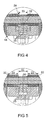
- the fixed abutment 17 of the spring 19 is present the base 34 of the U-shaped plate member 20 and has step-like arranged first contact surfaces 35 for each a first end 36 of several, forming the storage spring 19, Coil springs arranged concentrically one inside the other on.
- the movable abutment 18 is on the second ends 37 of the coil springs placed loosely and has further, similarly arranged step-like contact surfaces 38.
- the movable abutment 18 an internally threaded bore 39 and the fixed abutment 17 has a further bore 40 and the U-shaped plate member 20 has a third bore 41 on.
- the storage spring 19 by means of a one end with an external thread 42 and at the other Screw 44 provided at the end with a head piece 43 (see FIG 3) - supported on the U-shaped plate element - between their two abutments are biased.
- screw 44 is removed from the outside of base area 34 of the U-shaped plate element 20 through the bore 41 of the U-shaped plate element and the bore 40 of the fixed Abutment 17 inserted until they are with their Headpiece 43 is supported on the base 34.
- the storage spring formed from the coil springs 19 can be tightened further by means of the screw 44, until the lever 25 consisting of two parallel parts between the movable abutment 18 and the one on the top Bar element 21 and the lower bar element 22 are attached shock-absorbing elements 24 is insertable.
- the Lever 25 is a slot-like on the movable abutment 18 Recess 46 formed. Across this slit-like Recess 46 run two half-shell-shaped bearing surfaces 47 for one the ends of the two parts of the lever 25 penetrating bolt 48.
- the tensioned position of the latched spring can be released.
- By relaxing the Storage spring 19 acts by means of the movable abutment 18 driven lever 25 on the drive train of the movable Contact 2 until the contact arrangement 2, 3 is closed and latched.
- the moving strikes Abutment 18 by means of two upper mold surfaces 49 on the upper rod element 21 trained shock absorbers 23 and means two lower mold surfaces 50 on the lower rod element 22 trained shock absorbers 23.
- Abutment 18 Due to the guided by the lever 25 pivoting movement of the movable Abutment 18 acts part of the impact force tangentially the shock-absorbing sliding on the bolts 21, 22 Elements 24 so that a slight rotational movement of the shock-absorbing Elements in the direction of arrow 51 (see FIG. 2) is effected.
- Such a rotary movement occurs every stop of the movable abutment 18 on the shock absorbers, so that the shock absorbers and in particular the circumferential surface of their outer bushings evenly stressed become.
- the two parts of the lever 25 look up their decoupling from the movable abutment 18 on each one side of the two further axial sections 33 in the area where the rubber-elastic molded bodies are exposed. This is due to the rotary movement of the shock-absorbing Elements 24 also the entire circumferential surface of the rubber elastic Shaped body 32 evenly stressed.
- the rubber-elastic molded body 32 can have two parts and only in the area of the shock absorbers for the moving First axial sections 23 forming abutments the shock-absorbing elements be formed, then the Lever 25 within the further axial section 33 on the Inner socket 30 strikes.
Landscapes
- Driving Mechanisms And Operating Circuits Of Arc-Extinguishing High-Tension Switches (AREA)
Abstract
Description
Dabei zeigen
Claims (7)
- Energiespeicher (6), der mittels eines Hebels (25) an einen Antriebsstrang eines beweglichen Kontaktes (2) eines elektrischen Schalters angekoppelt ist und der eine zwischen einem feststehenden Widerlager (17) und einem beweglichen Widerlager (18) spannbare und mittels einer Stützanordnung gehaltene Speicherfeder (19) aufweist,
wobei die Stützanordnung das feste Widerlager der Speicherfeder trägt und einen Anschlag für das bewegliche Widerlager aufweist und
wobei die Stützanordnung, die Speicherfeder und die beiden Widerlager eine eigenständige Baueinheit bilden, die im Bereich nur eines der beiden Widerlager an einem Tragwerk (5) des Schalters positioniert ist,
dadurch gekennzeichnet, dass die Stützanordnung aus einem U-förmigen Plattenelement (20) und zwei quer zur Wirkrichtung der Speicherfeder (19) nebeneinander verlaufenden Stabelementen (21,22) besteht,
wobei die Stabelemente (21,22) die beiden Seitenflächen (29) des U-förmigen Plattenelementes (20) durchgreifend am Tragwerk (5) gehaltert sind und
wobei der Anschlag des beweglichen Widerlagers (18) als an den Stabelementen (21,22) angeordnete Stoßdämpfer (23) ausgebildet ist. - Energiespeicher nach Anspruch 1,
dadurch gekennzeichnet, dass die Stabelemente (21,22) als Bolzen mit kreisförmigem Profilquerschnitt ausgebildet sind und
dass die aus einer Innenbuchse (30), einer Außenbuchse (31) und einem zwischen diesen Buchsen angeordneten gummielastischen Formkörper (32) bestehenden Stoßdämpfer (23) gleitend auf den Bolzen aufgesetzt sind. - Energiespeicher nach einem der Ansprüche 1 oder 2,
dadurch gekennzeichnet, dass an dem beweglichen Widerlager (18) Formflächen (49,50), Lagerflächen (47) und eine Ausnehmung (46) ausgebildet sind,
wobei die Formflächen (49,50) den Stoßdämpfern (23) und die Lagerflächen (47) einem den Hebel (25) durchsetzenden Bolzen (48) zugeordnet sind und die Ausnehmung (46) zur Aufnahme des Hebels (25) dient und
wobei zur Entkopplung des Hebels (25) von dem beweglichen Widerlager (18) die Lagerflächen (47) halbschalenförmig und dabei auf der den Stabelementen (21,22) zugewandten Seite offen ausgebildet sind und der Hebel (25) im Zeitpunkt des Anschlagens des beweglichen Widerlagers (18) an den Stoßdämpfern (21,22) in seiner Schwenkrichtung einen freien Abstand (52) zu den Stabelementen (21,22) aufweist. - Energiespeicher nach Anspruch 3,
dadurch gekennzeichnet, dass die Stabelemente (21,22) jeweils einen weiteren, zum Anschlagen des Hebels dienenden Anschlag (33) aufweisen. - Energiespeicher nach Anspruch 4,
dadurch gekennzeichnet, dass der weitere Anschlag (33) stoßdämpfend ausgebildet ist. - Energiespeicher nach Anspruch 4,
dass an jedem der beiden Stabelemente (21,22) zwei Stoßdämpfer (23) angeordnet sind,
wobei die Stoßdämpfer (23) jeweils eines Stabelementes eine gemeinsame Innenbuchse (30) aufweisen, die zugleich den weiteren, dem Hebel (25) zugeordneten Anschlag (33) bildet. - Energiespeicher nach Anspruch 4,
dadurch gekennzeichnet, dass an jedem der beiden Stabelemente (21,22) zwei Stoßdämpfer (23) angeordnet sind,
wobei die Stoßdämpfer (23) jeweils eines Stabelementes eine gemeinsame Innenbuchse (30) sowie einen gemeinsamen gummielastischen Formkörper (32) aufweisen,
wobei der gummielastische Formkörper (32) den weiteren Anschlag (33) für den Hebel (25) bildet.
Applications Claiming Priority (2)
| Application Number | Priority Date | Filing Date | Title |
|---|---|---|---|
| DE10065090 | 2000-12-21 | ||
| DE2000165090 DE10065090C1 (de) | 2000-12-21 | 2000-12-21 | Energiespeicher für den Antrieb eines beweglichen Kontaktes eines elektrischen Schalters |
Publications (2)
| Publication Number | Publication Date |
|---|---|
| EP1220250A2 true EP1220250A2 (de) | 2002-07-03 |
| EP1220250A3 EP1220250A3 (de) | 2004-09-29 |
Family
ID=7669041
Family Applications (1)
| Application Number | Title | Priority Date | Filing Date |
|---|---|---|---|
| EP01250353A Withdrawn EP1220250A3 (de) | 2000-12-21 | 2001-10-08 | Energiespeicher für den Antrieb eines beweglichen Kontaktes eines elektrischen Schalters |
Country Status (2)
| Country | Link |
|---|---|
| EP (1) | EP1220250A3 (de) |
| DE (1) | DE10065090C1 (de) |
Families Citing this family (4)
| Publication number | Priority date | Publication date | Assignee | Title |
|---|---|---|---|---|
| DE102004021455B4 (de) | 2003-05-16 | 2005-10-27 | Siemens Ag | Niederspannungs-Leistungsschalter |
| DE102004061281A1 (de) * | 2004-12-14 | 2006-06-29 | Siemens Ag | Schaltvorrichtung mit erhöhter Leerschaltfestigkeit und entsprechendes Verfahren |
| US10199182B1 (en) | 2017-10-31 | 2019-02-05 | Siemens Aktiengesellschaft | Switch, in particular low-voltage circuit breaker, in plug-in technology with automatic unloading of the force store during withdrawal |
| CN109378248B (zh) * | 2018-12-10 | 2023-11-28 | 法腾电力装备江苏有限公司 | 小型高压柜正装三工位隔离开关 |
Family Cites Families (5)
| Publication number | Priority date | Publication date | Assignee | Title |
|---|---|---|---|---|
| GB496414A (en) * | 1937-06-30 | 1938-11-30 | English Electric Co Ltd | Improvements in spring mechanism |
| GB1384699A (en) * | 1971-10-15 | 1975-02-19 | Ass Elect Ind | Energy store actuators |
| US5302786A (en) * | 1992-10-19 | 1994-04-12 | General Electric Company | Molded case circuit breaker for remote control operations |
| FR2723252B1 (fr) * | 1994-08-01 | 1996-09-13 | Schneider Electric Sa | Mecanisme de disjoncteur equipe d'un dispositif a ccumulateur d'energie a butee d'amortissement |
| US6072136A (en) * | 1998-05-07 | 2000-06-06 | Eaton Corporation | Electrical switching apparatus with modular operating mechanism for mounting and controlling large compression close spring |
-
2000
- 2000-12-21 DE DE2000165090 patent/DE10065090C1/de not_active Expired - Fee Related
-
2001
- 2001-10-08 EP EP01250353A patent/EP1220250A3/de not_active Withdrawn
Also Published As
| Publication number | Publication date |
|---|---|
| EP1220250A3 (de) | 2004-09-29 |
| DE10065090C1 (de) | 2002-03-07 |
Similar Documents
| Publication | Publication Date | Title |
|---|---|---|
| DE69507218T2 (de) | Schaltermechanismus mit Energiespeicher mit Dämpfungsanschlag | |
| EP1359337B1 (de) | Zuspannvorrichtung für eine Scheibenbremse | |
| DE102007040163A1 (de) | Schaltgerät mit einer Schaltwelle zur Lagerung einer Drehkontaktbrücke sowie mehrpolige Schaltgeräteanordnung | |
| AT510917B1 (de) | Schaltvorrichtung | |
| DE102007013572B4 (de) | Kontaktsystem mit einer Schaltbrücke | |
| WO2002067280A1 (de) | Niederspannungs-leistungsschalter mit einer lageranordnung für die schaltwelle | |
| EP0606265B1 (de) | Mehrpoliger vakuumschalter mit einer polantriebseinheit für jede vakuumschaltröhre | |
| EP1220250A2 (de) | Energiespeicher für den Antrieb eines beweglichen Kontaktes eines elektrischen Schalters | |
| EP1984994B1 (de) | Endklemme mit Stoßdämpfer für eine Schleppleitung | |
| EP0970497B1 (de) | Schaltvorrichtung | |
| DE10056820A1 (de) | Kontaktanordnung für strombegrenzende Schutzschalter | |
| DE3906786C2 (de) | ||
| WO2001024208A1 (de) | Anordnung zur lagerung der schaltwelle eines niederspannungs-leistungsschalters und mehrpoliger niederspannungs-leistungsschalter mit einer anordnung zur lagerung der schaltwelle | |
| EP1180080A1 (de) | Einrichtung zum verstellen und zum elastischen verriegeln von beweglichen weichenteilen | |
| DE10252741B3 (de) | Kontaktsystem für einen Niederspannungsschalter | |
| DE102009055854B4 (de) | Auslöser für ein elektrisches Schaltgerät | |
| EP1011121B1 (de) | Druckgasschalter | |
| EP2385206B1 (de) | Schaltanordnung | |
| DE20121223U1 (de) | Antriebsstrang für einen bewegbaren Kontakt eines elektrischen Schalters | |
| DE102006044055B4 (de) | Elektrisches Schaltgerät mit wenigstens einer Kontaktstelle | |
| DE641521C (de) | Kontaktbruecke | |
| DE102006048124B4 (de) | Fangeinrichtung für einen Antriebsstrang | |
| WO1985000691A1 (fr) | Entrainement pour un interrupteur a vide | |
| DE9319264U1 (de) | Mitnehmerverbindung zwischen zwei linear in ihrer Längsrichtung beweglichen Bauteilen | |
| EP2397717A1 (de) | Brems- und/oder Festellvorrichtung eines auf einer Schiene verfahrbaren Schlittens |
Legal Events
| Date | Code | Title | Description |
|---|---|---|---|
| PUAI | Public reference made under article 153(3) epc to a published international application that has entered the european phase |
Free format text: ORIGINAL CODE: 0009012 |
|
| AK | Designated contracting states |
Kind code of ref document: A2 Designated state(s): AT BE CH CY DE DK ES FI FR GB GR IE IT LI LU MC NL PT SE TR |
|
| AX | Request for extension of the european patent |
Free format text: AL;LT;LV;MK;RO;SI |
|
| PUAL | Search report despatched |
Free format text: ORIGINAL CODE: 0009013 |
|
| AK | Designated contracting states |
Kind code of ref document: A3 Designated state(s): AT BE CH CY DE DK ES FI FR GB GR IE IT LI LU MC NL PT SE TR |
|
| AX | Request for extension of the european patent |
Extension state: AL LT LV MK RO SI |
|
| 17P | Request for examination filed |
Effective date: 20050120 |
|
| AKX | Designation fees paid |
Designated state(s): DE FR GB IT |
|
| STAA | Information on the status of an ep patent application or granted ep patent |
Free format text: STATUS: THE APPLICATION IS DEEMED TO BE WITHDRAWN |
|
| 18D | Application deemed to be withdrawn |
Effective date: 20080503 |