EP1220281A2 - Behandlungsverfahren mittels Mikrowellenplasma - Google Patents
Behandlungsverfahren mittels Mikrowellenplasma Download PDFInfo
- Publication number
- EP1220281A2 EP1220281A2 EP01310873A EP01310873A EP1220281A2 EP 1220281 A2 EP1220281 A2 EP 1220281A2 EP 01310873 A EP01310873 A EP 01310873A EP 01310873 A EP01310873 A EP 01310873A EP 1220281 A2 EP1220281 A2 EP 1220281A2
- Authority
- EP
- European Patent Office
- Prior art keywords
- plasma
- treatment
- microwave
- gas
- treating
- Prior art date
- Legal status (The legal status is an assumption and is not a legal conclusion. Google has not performed a legal analysis and makes no representation as to the accuracy of the status listed.)
- Granted
Links
Images




Classifications
-
- H—ELECTRICITY
- H01—ELECTRIC ELEMENTS
- H01J—ELECTRIC DISCHARGE TUBES OR DISCHARGE LAMPS
- H01J37/00—Discharge tubes with provision for introducing objects or material to be exposed to the discharge, e.g. for the purpose of examination or processing thereof
- H01J37/32—Gas-filled discharge tubes
- H01J37/32009—Arrangements for generation of plasma specially adapted for examination or treatment of objects, e.g. plasma sources
- H01J37/32192—Microwave generated discharge
-
- C—CHEMISTRY; METALLURGY
- C23—COATING METALLIC MATERIAL; COATING MATERIAL WITH METALLIC MATERIAL; CHEMICAL SURFACE TREATMENT; DIFFUSION TREATMENT OF METALLIC MATERIAL; COATING BY VACUUM EVAPORATION, BY SPUTTERING, BY ION IMPLANTATION OR BY CHEMICAL VAPOUR DEPOSITION, IN GENERAL; INHIBITING CORROSION OF METALLIC MATERIAL OR INCRUSTATION IN GENERAL
- C23C—COATING METALLIC MATERIAL; COATING MATERIAL WITH METALLIC MATERIAL; SURFACE TREATMENT OF METALLIC MATERIAL BY DIFFUSION INTO THE SURFACE, BY CHEMICAL CONVERSION OR SUBSTITUTION; COATING BY VACUUM EVAPORATION, BY SPUTTERING, BY ION IMPLANTATION OR BY CHEMICAL VAPOUR DEPOSITION, IN GENERAL
- C23C16/00—Chemical coating by decomposition of gaseous compounds, without leaving reaction products of surface material in the coating, i.e. chemical vapour deposition [CVD] processes
- C23C16/04—Coating on selected surface areas, e.g. using masks
- C23C16/045—Coating cavities or hollow spaces, e.g. interior of tubes; Infiltration of porous substrates
-
- C—CHEMISTRY; METALLURGY
- C23—COATING METALLIC MATERIAL; COATING MATERIAL WITH METALLIC MATERIAL; CHEMICAL SURFACE TREATMENT; DIFFUSION TREATMENT OF METALLIC MATERIAL; COATING BY VACUUM EVAPORATION, BY SPUTTERING, BY ION IMPLANTATION OR BY CHEMICAL VAPOUR DEPOSITION, IN GENERAL; INHIBITING CORROSION OF METALLIC MATERIAL OR INCRUSTATION IN GENERAL
- C23C—COATING METALLIC MATERIAL; COATING MATERIAL WITH METALLIC MATERIAL; SURFACE TREATMENT OF METALLIC MATERIAL BY DIFFUSION INTO THE SURFACE, BY CHEMICAL CONVERSION OR SUBSTITUTION; COATING BY VACUUM EVAPORATION, BY SPUTTERING, BY ION IMPLANTATION OR BY CHEMICAL VAPOUR DEPOSITION, IN GENERAL
- C23C16/00—Chemical coating by decomposition of gaseous compounds, without leaving reaction products of surface material in the coating, i.e. chemical vapour deposition [CVD] processes
- C23C16/22—Chemical coating by decomposition of gaseous compounds, without leaving reaction products of surface material in the coating, i.e. chemical vapour deposition [CVD] processes characterised by the deposition of inorganic material, other than metallic material
- C23C16/26—Deposition of carbon only
-
- C—CHEMISTRY; METALLURGY
- C23—COATING METALLIC MATERIAL; COATING MATERIAL WITH METALLIC MATERIAL; CHEMICAL SURFACE TREATMENT; DIFFUSION TREATMENT OF METALLIC MATERIAL; COATING BY VACUUM EVAPORATION, BY SPUTTERING, BY ION IMPLANTATION OR BY CHEMICAL VAPOUR DEPOSITION, IN GENERAL; INHIBITING CORROSION OF METALLIC MATERIAL OR INCRUSTATION IN GENERAL
- C23C—COATING METALLIC MATERIAL; COATING MATERIAL WITH METALLIC MATERIAL; SURFACE TREATMENT OF METALLIC MATERIAL BY DIFFUSION INTO THE SURFACE, BY CHEMICAL CONVERSION OR SUBSTITUTION; COATING BY VACUUM EVAPORATION, BY SPUTTERING, BY ION IMPLANTATION OR BY CHEMICAL VAPOUR DEPOSITION, IN GENERAL
- C23C16/00—Chemical coating by decomposition of gaseous compounds, without leaving reaction products of surface material in the coating, i.e. chemical vapour deposition [CVD] processes
- C23C16/44—Chemical coating by decomposition of gaseous compounds, without leaving reaction products of surface material in the coating, i.e. chemical vapour deposition [CVD] processes characterised by the method of coating
- C23C16/50—Chemical coating by decomposition of gaseous compounds, without leaving reaction products of surface material in the coating, i.e. chemical vapour deposition [CVD] processes characterised by the method of coating using electric discharges
- C23C16/511—Chemical coating by decomposition of gaseous compounds, without leaving reaction products of surface material in the coating, i.e. chemical vapour deposition [CVD] processes characterised by the method of coating using electric discharges using microwave discharges
Definitions
- the present invention is related to a method of treatment with a microwave plasma. More specifically, the invention is related to a method of treatment with a microwave plasma, which is capable of forming a plasma in a short period of time maintaining stability in conducting the treatment with a microwave plasma in order to chemically deposit a film on a substrate.
- the chemical vapor deposition is a technology for precipitating a reaction product like a film on the surface of a substrate relying upon the vapor growth in a high-temperature atmosphere by using a starting material gas that does not undergo a reaction at normal temperature.
- the CVD has been widely employed for the manufacture of semiconductors and for reforming the surfaces of metals and ceramics. In recent years, the CVD has been employed even for reforming the surfaces of plastic containers and, particularly, for improving gas barrier properties.
- a plastic container having a deposited carbon film has been known already as a plastic material with a chemically deposited film.
- Japanese Unexamined Patent Publication (Kokai) No. 53116/1996 discloses a plastic container coated with a carbon film characterized in that a hard carbon film is formed on the inner wall surface of a container formed of a plastic material.
- the plasma CVD is a process for growing a thin film by utilizing a plasma. That is, the plasma CVD basically comprises decomposing a gas containing a staring material gas with electric energy of an intense electric field under a reduced pressure, to deposit, on a substrate, a substance that is formed through a chemical reaction in the gaseous phase or on the substrate.
- the plasmic state is realized by a glow discharge.
- a method that utilizes a DC glow discharge a method that utilizes a high-frequency glow discharge and a method that utilizes a microwave discharge.
- a carbon film is deposited on the inner wall surface of the container based on the high-frequency glow discharge by using a so-called capacity-coupled CVD apparatus having an internal electrode arranged in the container and an external electrode arranged outside the container accompanied, however, by such problems that the constitution of the apparatus is complex and the operation becomes complex, too.
- the treatment with a microwave plasma involves a considerable degree of time lag (for example, about 10 seconds) between the introduction of microwaves and the generation of plasma, the time lag being not constant but subject to change to a considerable degree depending upon each treatment. Therefore, difficulty is involved in controlling the treatment conditions and the effect of treatment is not stable, either.
- Another object of the present invention is to provide a method of treatment with a microwave plasma capable of forming a film having particularly excellent gas shut-off property (gas barrier property) on, for example, the inner surface and/or the outer surface of the container.
- a method of treatment with a microwave plasma by maintaining a reduced pressure in a plasma-treating chamber for treatment with a plasma in which a substrate that is to be treated is contained, introducing a treating gas into the plasma-treating chamber and introducing microwaves into the plasma-treating chamber, wherein a metallic antenna is disposed in the plasma-treating chamber to generate a plasma in a short period of time maintaining stability.
- an end of the metallic antenna is positioned on an extension in the horizontal direction from an upper end or a lower end of a microwave introduction port formed in the plasma-treating chamber, or in the vicinity thereof.
- a film of the same kind as the film formed on the surface of the substrate by the treatment with a plasma is formed on the surface of the metallic antenna. This effectively avoids a drop in the performance of the film on the surface of the substrate caused by sputtering that occurs during the treatment with a plasma.
- the supply pipe for supplying a treating gas is a porous pipe such as the one formed of a porous material having, for example, a nominal filtering precision of from 1 to 300 ⁇ m and a pressure loss on the secondary side under the atmospheric pressure of from 0.01 to 25 KPa.
- a porous pipe By using such a porous pipe, it is allowed to form a film having excellent gas barrier property on the surface of the substrate.
- the nominal filtering precision stands for one of the characteristic values employed when a porous material is used as a filter.
- a nominal filtering precision of 130 ⁇ m stands for that when the porous material is used as the filter, foreign matters having particle diameters of not smaller than 130 ⁇ m can be trapped.
- the treatment is conducted with a microwave plasma by maintaining a reduced pressure in a plasma-treating chamber in which a substrate that is to be treated is contained, introducing a treating gas into the plasma-treating chamber and introducing microwaves into the plasma-treating chamber, wherein a metallic antenna is disposed in the plasma-treating chamber to generate a plasma in a short period of time maintaining stability.
- the treatment with a microwave plasma is conduted by utilzing a plasma generated by a glow discharge like any other treatment with plasma.
- a gas is an insulator but exhibits electric conductivity as the neutral molecules thereof are ionized. This state is called gaseous electric discharge.
- the gaseous electric discharge can roughly be divided into a corona discharge, a glow discharge and an arc discharge depending upon the type of electric discharge.
- the corona discharge stands for the one in a state where the electric discharge is locally sustaining in a non-uniform electric field such as an electric field established by an electrode having a sharp end, whereas the glow discharge and the arc discharge are those which take place in a uniform electric field.
- the glow discharge shines less brightly, heats the gas at a lower temperature, and produces a smaller discharge current density, but takes place stably in a gas of a low pressure making a difference.
- a general glow discharge gaseous ions that exist in small amounts in a dark current region are gradually accelerated with an increase in the electrode voltage, come into collision with neutral molecules to ionize them, whereby the newly formed electrons further ionize other molecules, and the cations impinge upon the surface of the cathode to release electrons therefrom. Repetition of this cycle develops progressively and reaches a steady state called glow discharge where the formation of electron maintains a balance with the extinction of ions due to diffusion and recombination.
- a mechanism for generating a glow discharge in the treatment with a microwave plasma is the same as the above-mentioned mechanism with the exception of introducing microwaves instead of applying a voltage to the electrode.
- the induction period becomes as long as 10 seconds when the microwave output is 960 watts and the degree of vacuum is 100 Pa, and it often happens that no electric discharge takes place within the treating time.
- the induction period can be shortened to be several seconds or less as will be demonstrated by examples appearing later and, besides, the induction period is stabilized, which are unexpected effects of the present invention.
- thermoelectrons are emitted from the antenna and, besides, electrons are emitted due to bombardment of cations upon the fine wire.
- the plasma can be formed in a short period of time and stably in conducting the treatment with a microwave plasma, i.e., the plasma can be generated within a very short period of time from when the microwaves are introduced into the plasma-treating chamber, the plasma that is generated remaining stable making it possible to stably conduct the treatment.
- the induction period for generating the plasma is shortened and becomes constant, making it possible to improve efficiency of the treatment with a plasma and to correctly and easily control the step of treatment with a plasma.
- the length L of the metallic antenna is set to be not smaller than 0.02 times as great as the wavelength of the microwaves from the standpoint of shortening the induction period until the plasma discharge takes place.
- Fig. 1 in the accompanying drawings is plotted a relationship between the length L (mm) of a fine metal wire (needle) and the induction period (sec) until the plasma discharge takes place when there are used microwaves of a frequency of 2.45 GHz.
- Fig. 1 shows an interesting fact in that the induction period includes a minimum portion concerning the length of the fine wire, and the minimum portion corresponds to one-fourth of the wavelength ⁇ of the microwaves.
- the induction period for the plasma discharge can be minimized by so selecting the length L of the fine metal wire as to establish a resonating relationship with the microwaves.
- the apparatus used for the invention includes a plasma-treating chamber in which a substrate that is to be treated is contained, an exhaust system for maintaining the plasma-treating chamber in a reduced-pressure condition, a treating gas introduction system for introducing the reacting gas into the plasma-treating chamber, and a microwave introduction system for generating a plasma in the plasma-treating chamber, wherein a metallic antenna is disposed in the plasma-treating chamber.
- Fig. 2 schematically illustrates the arrangement of the apparatus for treatment with a plasma used in the present invention.
- the plasma-treating chamber generally designated at 1 is connected, via an exhaust pipe 2, to a vacuum pump 2 for maintaining a reduced pressure in the plasma-treating chamber 1, and is further connected to a microwave oscillator 4 via a waveguide 5.
- the waveguide 5 is provided with a triple tuner 6 for minimizing the amount of reflection of microwave from the plasma-treating chamber.
- the plasma-treating chamber 1 is provided with a short plunger 7 for adjusting the load of the plasma-treating chamber.
- a bottle 8 in this case, is treated with a plasma, the bottle 8 being held upside down in the plasma-treating chamber.
- a supply pipe 9 is inserted in the bottle 8 for supplying a treating gas, and a metallic antenna 10 is extending upward from an end of the pipe 9.
- the bottle 8 to be treated is, first, mounted on a bottle holder (not shown).
- the bottle 8 and the bottle holder are maintained in an air-tight state, and a vacuum pump 2 is driven to maintain the interior of the bottle 8 in a vacuum state.
- the pressure may be reduced in the plasma-treating chamber 1 outside the bottle.
- the degree of pressure reduction in the bottle 8 achieved by the vacuum pump 2 is such that the treating gas is introduced and the microwaves are introduced to generate a glow discharge.
- the degree of pressure reduction in the plasma-treating chamber 1 is such that the glow discharge is not generated despite the microwaves are introduced.
- the treating gas is introduced into the bottle 8 from the treating gas supply pipe 9, and microwaves are introduced into the plasma-treating chamber 1 via the waveguide 5.
- a plasma is stably generated within a very short period of time due to the glow discharge since electrons are emitted from the metallic antenna 10.
- the temperature of electrons in the plasma is several tens of thousands of degrees in K whereas the temperature of the gaseous ions is several hundreds of degrees in K, which is about one-hundredth, creating a thermally non-equilibrium state and making it possible to effectively treat even a plastic substrate of a low temperature with a plasma.
- the predetermined treatment is conducted with a plasma
- neither the treating gas nor the microwaves are introduced, the air is gradually introduced through the exhaust pipe 3, the pressures inside and outside of the container are brought to normal pressure, and the bottle treated with a plasma is taken out of the plasma-treating chamber 1.
- the substrate to be treated may be made of plastic materials or ceramics.
- thermoplastic resins that have been known per se, i.e., such as low-density polyethylene, high-density polyethylene, polypropylene, poly 1-butene, poly 4-methyl-1-pentene or polyolefins as random or block copolymers of ⁇ -olefins, ethylene, propylene, 1-butene, 4-methyl-1-pentene; ethylene-vinyl compound copolymers such as ethylene-vinyl acetate copolymer, ethylene-vinyl alcohol copolymer, and ethylene-vinyl chloride copolymer; styrene resins such as polystyrene, acrylonitrile-styrene copolymer, ABS, and ⁇ -methyl styrene-styrene copolymer; polyvinyl compounds such as polyvinyl chloride, polyvinylidene chloride, vinyl chloride-vinylidene chloride copoly
- the ceramics there can be exemplified various glasses, earthenwares, ceramics; oxide ceramics such as alumina, silica, titania and zirconia; nitride ceramics such as aluminum nitride, boron nitride, titanium nitride, silicon nitride and zirconium nitride; carbide ceramics such as silicon carbide, boron carbide, tungsten carbide and titanium carbide; boride ceramics such as silicon boride, titanium boride and zirconium boride; highly dielectric ceramics such as rutile, magnesium titanate, zinc titanate and rutile-lanthanum oxide; piezoelectric ceramics such as lead titanate; and various ferrites.
- oxide ceramics such as alumina, silica, titania and zirconia
- nitride ceramics such as aluminum nitride, boron nitride, titanium nitride, silicon nitride and zi
- These substrates may be used as films or sheets, or may be put to the treatment with a plasma of the present invention in the form of containers such as bottles, cups and tubes or in the form of any other molded articles.
- biaxially stretch-blow-molded bottles formed of polyester such as polyethylene terephthalate.
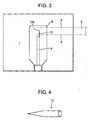
- the metallic antenna for shortening the induction period for glow discharge by microwaves there can be used the one of the form of a fine wire having a sharp end as shown in Fig. 4 or the one of the form of a foil as shown in Fig. 5 having a length lying within the above-mentioned range.
- the antenna of the form of a fine wire has a diameter of usually from 0.2 to 10 mm
- the antenna of the form of a foil has a width of from 1 to 10 mm and a thickness of from about 5 to about 500 ⁇ m.
- the fine wire generates heat and must have excellent heat resistance.
- the fine wire is made of, for example, platinum, stainless steel, copper, carbon, aluminum or steel.
- the metallic antenna has a length L which is not smaller than 0.02 times as great as the wavelength of the microwaves as described already.
- the end of the metallic antenna is located at a portion where the electric field is intense. Referring, for example, to Fig. 3, it is desired that the end 10a of the metallic antenna is positioned on an extension (designated at X in Fig. 3) from an upper end or a lower end of a microwave introduction port (end of the waveguide 5) formed in the side surface of the plasma-treating chamber 1, or in the vicinity thereof (e.g., within ⁇ 10 mm from the extension X).
- the surface of the metallic antenna is a film of the same kind as the film formed on the surface of the substrate by the plasma-treatment. That is, in conducting the plasma-treatment, the surface of the metallic antenna is attacked by ions to develop a so-called etching phenomenon, whereby the etched substance deposits on the surface of the substrate to be treated with a plasma (this is the same phenomenon as the sputtering which is a kind of PVD method). As the sputtering occurs from the surface of the metallic antenna, the composition of the film 'formed on the surface of the substrate becomes inhomogeneous spoiling properties of the film, i.e., spoiling such properties as gas shut-off property and electric conductivity. Upon forming, on the surface of the metallic antenna, the film of the same kind as the film formed by the plasma-treatment, however, it is allowed to reliably prevent other elements due to sputtering from entering into the film formed on the surface of the substrate.
- the supply pipe for supplying a treating gas into the plasma-treating chamber may be made of any material. It is here desired that even this pipe is coated on the surface thereof with the film of the same kind as the film formed on the surface of the substrate by the plasma-treatment like the above-mentioned metallic antenna.
- the pipe made of a metal can also be utilized as the metallic antenna.
- the length of the metallic pipe, position of the end thereof and the diameter thereof are selected to be as those of the above-mentioned metallic antenna.
- a metallic antenna in the form of a fine wire or a foil to the outer side of the metallic pipe (in the direction in which the pipe extends)
- the whole pipe can be used as the metallic antenna.
- the overall length, position of the end and the like are selected in the same manner as those of the above-mentioned metallic antenna.
- the supply pipe is a porous pipe, e.g., the one made of a porous material having a nominal filtering precision in a range of from 1 to 300 ⁇ m and a pressure loss on the secondary side under the atmospheric pressure in a range of from 0.01 to 25 KPa.
- the container having the film formed by the plasma-treatment exhibits an oxygen permeability of 4.8 cc and a loss of carbonic acid gas of a level of 1.4%/week.
- the porous pipe having a nominal filtering precision that lies within the above-mentioned range the container exhibits the oxygen permeability which is suppressed to be smaller than 1 cc and a loss of carbonic acid gas which is suppressed to a level of 0.5%/week or smaller.
- the pressure loss on the secondary side under the atmospheric pressure lies within the above-mentioned range (0.01 to 25 KPa).
- the pressure loss lies outside the above-mentioned range, the gas barrier property is not so much improved.
- the gas barrier property of the treated container is greatly affected by the manner of supplying a treating gas since the film chemically deposited on the container has a uniform thickness. That is, the chemically deposited film has a very small thickness and, hence, uniformity in the thickness seriously affects the gas barrier property. For example, if there exists a portion where the thickness is small despite the amount of deposition as a whole is the same, the gas permeates through the portion of a small thickness to a large extent and, as a result, the chemically deposited film as a whole exhibits decreased gas barrier property.
- the film (silicon oxide film) formed by the treatment with a plasma exhibited fluctuation in the thickness to a considerable degree when there is used the perforated pipe having holes 0.8 mm in diameters (Reference Example 7).
- a fluctuation was not observed when there was used a porous pipe satisfying the above-mentioned conditions of nominal filtering precision and pressure loss.
- the present inventors are aware of the problem that really occurs in that the gas is not evenly supplied onto the substrate that is to be treated with a plasma; i.e., some portions on the surface of the substrate are supplied with the gas to a sufficient degree forming the film deposited thereon but other portions on the surface of the substrate are not supplied with a sufficient amount of gas and the film is not deposited thereon at all.
- a predetermined pressure loss occurs as the gas passes through the pipe; i.e., the gas is uniformly blown out from the whole surface of the porous pipe and is uniformly supplied onto the whole surface of the substrate such as the container making it possible to deposit a film maintaining a uniform thickness.
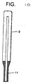
- Fig. 10 illustrates an example of the porous pipe used as the supply pipe 9 for supplying a treating gas.
- the supply pipe 9 comprises a porous cylindrical member with bottom having its one end welded to a hollow support member 11 and having its other end closed.
- the porous material there can be exemplified a sintered metal such as bronze or stainless steel.
- the above-mentioned cylinder with bottom can be prepared by molding a bronze powder or a stainless steel powder, followed by firing. It is also allowable to prepare the cylinder by sintering it in a metal mold, as a matter of course.
- the porous material constituting the supply pipe 9 is not limited to the above-mentioned sintered metals only, but may be obtained by sintering and molding a plastic powder such as of polypropyrene, ultrahigh molecular-weight polyethylene and polytetrafluoroethylene (PTFE), or may be obtained by sintering and molding a ceramic material.
- a treating gas there can be used a variety of gases known per se depending upon the object of treatment with a plasma.
- a crosslinked structure may be introduced into the surface of the plastic substrate by using a carbonic acid gas.
- properties same as those of a polytetrafluoroethylene, such as non-sticking property, low coefficient of friction, heat resistance and resistance against chemicals, may be imparted to the surface of the plastic substrate by using a fluorine gas.
- a compound containing atoms, molecules or ions for constituting the thin film is rendered to be in a gaseous phase and is carried by a suitable gas.
- the starting compound must be highly volatile, and a carbon film or a carbide film is formed by using hydrocarbons such as methane» ethane, ethylene or acetylene. Further, a silicon film is formed by using silicon tetrachloride, silane, organosilane compound or organosiloxane compound. There can be used a halogen compound (chloride) or an organometal compound, such as titanium, zirconium, tin, aluminum, yttrium, molybdenum, tungsten, gallium, tantalum, niobium, iron, nickel, chromium or boron.
- chloride halogen compound
- organometal compound such as titanium, zirconium, tin, aluminum, yttrium, molybdenum, tungsten, gallium, tantalum, niobium, iron, nickel, chromium or boron.
- an oxygen gas is used for forming an oxide film
- a nitrogen gas or an ammonia gas is used for forming a nitride film.
- These starting gases can be used in two or more kinds in a suitable combination depending upon the chemical composition of the thin film that is to be formed.
- the carrier gas there can be used argon, neon, helium, xenone or hydrogen.
- the plasma-treating chamber must be maintained at a degree of vacuum at which a glow discharge takes place and must, in general, be maintained in a range of from 1 to 500 Pa and, particularly desirably, from 5 to 200 Pa to establish a microwave discharge to efficiently conduct the treatment with a plasma.
- the amount of introducing the starting gas varies depending upon the surface area of the substrate to be treated or upon the kind of the starting gas. In treating the surfaces of the plastic container, however, it is desired that the starting gas is supplied at a flow rate of from 1 to 500 cc/min and, particularly, from 2 to 200 cc/min per a container under a standard state.
- one starting gas may be supplied in an excess amount.
- the oxygen gas in an excess amount compared to the silicon-source gas.
- nitrogen or ammonia may be supplied in an excess amount compared to the metal-source gas.
- microwaves for generating a glow discharge there can be used those of frequencies that are permitted to be used industrially. In Japan, for example, it is desired to use microwaves having frequencies of 2.45 GHz, 5.8 GHz and 22.125 GHz.
- the output of microwaves may differ depending upon the surface area of the substrate to be treated or the kind of the starting material gas. In treating the surfaces of the plastic container, however, it is desired that the microwaves are supplied in an electric power of from 50 to 1500 watts and, particularly, from 100 to 1000 watts per a container.
- the time for treatment with a plasma varies depending upon the surface area of the substrate to be treated, thickness of the film to be formed and kind of the starting material gas, and cannot be exclusively specified. If described with reference to treating the plastic container with a plasma, however, the time of not shorter than one second per a container is necessary from the standpoint of stable treatment with a plasma. Though it is requested to shorten the time from the viewpoint of cost, the time may be of the order of minutes if necessary.
- the film is favorably deposited and, besides, can be deposited on all of the surfaces.
- the substrate to be treated is a solid molded article like a plastic container
- the interior and/or the exterior of the plastic container are maintained in a reduced pressure atmosphere containing a treating gas, and a microwave discharge is established inside of the container and/or outside of the container to chemically deposit a film on the inner surface and/or on the outer surface of the container.
- the plastic container is held in the plasma-treating chamber, the exterior of the plastic container and the interior of the plastic container are maintained in an air-tight state, the interior of the plastic container into which the treating gas is introduced is maintained in a reduced pressure condition where a microwave discharge will take place, the exterior of the plastic container is maintained in a reduced pressure condition where the microwave discharge will not take place while introducing the treating gas into the interior of the plastic container, and microwaves are introduced into the exterior of the plastic container in the plasma-treating chamber thereby to conduct the treatment with a plasma.
- the surface of a PP (polypropylene) film F was treated with a microwave plasma by using a microwave oscillator of a frequency of 2.45 GHz and a maximum output of 1.5 KW, a metallic cylindrical chamber for treatment with a plasma (plasma-treating chamber) having a diameter of 300 mm and a height of 300 mm, a hydraulically operated vacuum pump for evacuating the chamber and a rectangular waveguide for introducing the microwaves from the oscillator into the chamber with a microwave plasma shown in Fig. 2 (not using a short plunger).
- a substrate-holding plate 20 In the chamber were installed, as shown in Fig. 6, a substrate-holding plate 20, a ceramic gas supply pipe 9 having a treating gas introduction port, and a stainless steel fine wire (antenna) 10 having a diameter of 1 mm and a length of 30 mm with its end being shaped like a needle and being installed in the gas introduction port of the pipe 9.
- a stainless steel fine wire (antenna) 10 having a diameter of 1 mm and a length of 30 mm with its end being shaped like a needle and being installed in the gas introduction port of the pipe 9.
- a polypropylene (PP) film F having a thickness of 70 ⁇ m was placed on the substrate-holding plate 20, and the vacuum pump was operated until the degree of vacuum was 2 Pa. While operating the vacuum pump, an oxygen gas was introduced until the degree of vacuum was 50 Pa, and microwaves of 0.15 KW were oscillated from the microwave oscillator. An oxygen plasma was generated in shorter than one second from the oscillation of microwaves.
- the surface of the PP film F was treated with the oxygen plasma for 3 seconds, and the surface of the treated PP film was measured for its applicability. As a result, the PP film F exhibited a surface energy of 30 dynes/cm before the treatment and exhibited a surface energy of 50 dynes/cm after the treatment.
- the surface of the PP film F was treated in the same manner as in Example 1 with the exception of removing the fine wire-like antenna 10 of stainless steel from the plasma-treating chamber.
- a carbon film was deposited on the outer surfaces of PET cups C relying upon a microwave plasma by using a microwave oscillator of a frequency of 2.45 GHz and a maximum output of 1.5 KW, a metallic cylindrical chamber (plasma-treating) having a diameter of 300 mm and a height of 300 mm, a hydraulically operated vacuum pump for evacuating the chamber and a rectangular waveguide for introducing the microwaves from the oscillator into the chamber shown in Fig. 2 (not using a short plunger).
- a microwave oscillator of a frequency of 2.45 GHz and a maximum output of 1.5 KW
- a metallic cylindrical chamber having a diameter of 300 mm and a height of 300 mm
- a hydraulically operated vacuum pump for evacuating the chamber
- a rectangular waveguide for introducing the microwaves from the oscillator into the chamber shown in Fig. 2 (not using a short plunger).
- a cup holder 22 In the chamber were installed, as shown in Fig. 7, a cup holder 22, a ceramic gas supply pipe 9 having a treating gas introduction port, and a fine-wire antenna 10 of copper having a diameter of 1 mm with its both ends being shaped like a needle and being installed in the gas introduction port of the pipe 9. There were used the antennas 10 having lengths changing from 5 to 60 mm at intervals of 5 mm. The treatment was conducted as described below.
- PET cups C having a mouth diameter of 60 mm and a height of 90 mm were placed on the cup holder in a manner as shown in Fig. 7, and the vacuum pump was operated until the degree of vacuum was 2 Pa. While operating the vacuum pump, a mixture gas of an acetylene gas and an argon gas was introduced until the degree of vacuum was 50 Pa, and microwaves of 0.6 KW were oscillated from the microwave oscillator. Times were measured until an acetylene-argon plasma was generated after the oscillation of microwaves. The results were as shown in Table 1.
- the outer surfaces of the PET cups C were treated with this plasma for 5 seconds.
- the surfaces of the PET cups C treated with the plasma were measured concerning the presence of a carbon film and the film thickness by using Laser-Raman and ellipsometer. It was confirmed that the carbon film had been deposited on all cups C, the thickness of the film being about 20 nm.
- Lengths of the fine wires and times until the acetylene-argon plasma generates Lengths of fine wires (mm) 5 10 15 20 30 40 50 60 Times until plasma generates (sec) 1.5 1.3 1.1 0.8 0.7 1.0 1.4 2.0
- the surfaces of the PET cups C were treated 5 times in the same manner as in Example 2 but removing the fine-wire antenna 10 of copper from the plasma-treating chamber.
- a silicon oxide film was deposited on the inner surface of a PET bottle B relying upon a microwave plasma by using a microwave oscillator of a frequency of 2.45 GHz and a maximum output of 1.5 KW, a metallic cylindrical chamber (plasma-treating chamber) having a diameter of 300 mm and a height of 300 mm, a hydraulically operated vacuum pump for evacuating the plasma-treating chamber and a rectangular waveguide for introducing the microwaves from the oscillator into the plasma-treating chamber shown in Fig. 2 (not using a short plunger).
- a microwave oscillator of a frequency of 2.45 GHz and a maximum output of 1.5 KW
- a metallic cylindrical chamber having a diameter of 300 mm and a height of 300 mm
- a hydraulically operated vacuum pump for evacuating the plasma-treating chamber
- a rectangular waveguide for introducing the microwaves from the oscillator into the plasma-treating chamber shown in Fig. 2 (not using a short plunger).
- a bottle holder 25 In the plasma-treating chamber were installed, as shown in Fig. 8, a bottle holder 25, a ceramic gas supply pipe 9, and a fine-wire antenna 10 of aluminum having a diameter of 1 mm and a length of 30 mm with its end being shaped like a needle and being installed at an end of the gas supply pipe 9.
- the PET bottle B having a mouth diameter of 28 mm and a height of 220 mm was placed on the bottle holder 25 in a manner as shown, and the vacuum pup was operated so that the interior of the chamber was evacuated to a degree of evacuation of 2 KPa outside the bottle and to a degree of evacuation of 2 Pa inside the bottle.
- a mixture gas of a hexamethyldisiloxane (HMDSO) gas and an oxygen gas was introduced until the degree of vacuum in the bottle was 50 Pa, and microwaves of 0.3 KW were oscillated from the microwave oscillator. Times were measured until an HMDSO-oxygen plasma was generated after the oscillation of microwaves. The results were as shown in Table 3.
- HMDSO hexamethyldisiloxane
- a silicon oxide film was deposited on the inner surface of a PET bottle B relying upon a microwave plasma by using a microwave oscillator of a frequency of 2.45 GHz and a maximum output of 1.5 KW, a metallic cylindrical chamber (plasma-treating chamber) having a diameter of 300 mm and a height of 300 mm, a hydraulically operated vacuum pump for evacuating the chamber and a rectangular waveguide for introducing the microwaves from the oscillator into the chamber shown in Fig. 2 (not using a short plunger).
- a microwave oscillator of a frequency of 2.45 GHz and a maximum output of 1.5 KW
- a metallic cylindrical chamber plasma-treating chamber having a diameter of 300 mm and a height of 300 mm
- a hydraulically operated vacuum pump for evacuating the chamber
- a rectangular waveguide for introducing the microwaves from the oscillator into the chamber shown in Fig. 2 (not using a short plunger).
- the PET bottle B having a mouth diameter of 28 mm and a height of 220 mm was placed on the bottle holder 25 in a manner as shown, and the vacuum pump was operated so that the degree of vacuum outside the bottle in the plasma-treating chamber was 2 Pa and further that the degree of vacuum inside the bottle was 2 Pa.
- a mixture gas of a hexamethyldisiloxane (HMDSO) gas and an oxygen gas was introduced until the degree of vacuum in the bottle was 100 Pa, and microwaves of 0.3 KW were oscillated from the microwave oscillator.
- An HMDSO-oxygen plasma was generated in the bottle in less than one second from the oscillation of microwaves.
- the inner surface of the PET bottle B was treated with this plasma for 5 seconds.
- the inner surface of the PET bottle B treated with the plasma was measured concerning the presence of silicon relying upon the X-ray fluorescence analysis to confirm that silicon had been deposited.
- the silicon compound was analyzed by FT-IR to confirm it to be a silicon oxide film.
- the air containing sand having average particle diameters of 0.5, 1, 2, 5, 10, 20, 40, 70, 100, 120, 150, 300 and 500 ⁇ m was blown in a predetermined amount for a predetermine period of time onto a sintered product. Minimum diameters of particles that did not pass through the sintered product were measured and were regarded to be nominal filtering precisions.
- a conduit equipped with a flow meter and a micro-pressure gauge was installed on the primary side of the sintered product, the secondary side of the sintered product was opened to the atmospheric pressure, and the air was flown at normal temperature from the primary side at a rate of one liter/min/cm 2 .
- the pressure was measured on the primary side and was regarded to be a pressure loss of the sintered product.
- the interior of the bottle to be measured was substituted with a nitrogen gas, the mouth of the bottle was sealed with a laminate of aluminum foils with a sealant, the bottle was preserved in an environment of 30 ° C, 80%RH and 21% of oxygen.
- the concentration of oxygen gas in the bottle was measured with the passage of time to find the permeability of oxygen gas.
- a known amount of dry ice was introduced into the bottle, the mouth of the bottle was sealed with the laminate of aluminum foils with a sealant, and the loss of weight was measured with the passage of time to calculate the loss of carbonic acid gas.
- an apparatus for treatment with a plasma of a structure shown in Fig. 2 including a microwave oscillator of a frequency of 2.45 GHz and a maximum output of 1.5 KW, a metallic cylindrical chamber (plasma-treating) having a diameter of 300 mm and a height of 300 mm, a hydraulically operated vacuum pump for evacuating the chamber, and a rectangular waveguide for introducing the microwaves from the oscillator into the chamber.
- a microwave oscillator of a frequency of 2.45 GHz and a maximum output of 1.5 KW
- a metallic cylindrical chamber having a diameter of 300 mm and a height of 300 mm
- a hydraulically operated vacuum pump for evacuating the chamber
- a rectangular waveguide for introducing the microwaves from the oscillator into the chamber.
- a bottle holder 25 In the chamber were installed, as shown in Fig. 8, a bottle holder 25, a gas supply pipe 9, and a wire-like antenna 10 of a stainless steel having a diameter of 0.5 mm and a length of 50 mm with its end being shaped like a needle and being attached to an end of the pipe 9. There was further provided a hydraulically operated vacuum pump for evacuating the interior of the bottle.
- the gas supply pipe 9 there was used a porous pipe with bottom made of a sintered stainless steel having an outer diameter of 10 mm, a length of 180 mm and a nominal filter ⁇ ng precision of 120 ⁇ m.
- PET bottle A cylindrical polyethylene terephthalate bottle (hereinafter referred to as PET bottle) having a mouth diameter of 28 mm and a height of 220 mm was placed on the bottle holder 25, and the interior of the plasma-treating chamber was evacuated so that the degree of vacuum was 2 KPa on the outside the bottle. While operating the vacuum pump, there were introduced 2 sccm of a hexamethyldisiloxane (HMDSO) gas, 20 sccm of an oxygen gas and 50 sccm of an argon gas to adjust the degree of vacuum in the bottle to be 50 Pa. Microwaves of 300 watts were oscillated from the microwave oscillator to form a plasma in the bottle thereby to conduct the treatment with a plasma for 10 seconds.
- HMDSO hexamethyldisiloxane
- the PET bottle was treated with a plasma in the same manner as in Reference Example 1 but using the porous pipe made of a sintered bronze having a nominal filtering precision of 70 ⁇ m.
- the results of measurement and evaluation were as shown in Table 4.
- the PET bottle was treated with a plasma in the same manner as in Reference Example 1 but using the porous pipe made of a sintered polypropylene having a nominal filtering precision of 150 ⁇ m.
- the results of measurement and evaluation were as shown in Table 4.
- the PET bottle was treated with a plasma in the same manner as in Reference Example 1 but using the porous pipe made of a sintered stainless steel having a nominal filtering precision of 40 ⁇ m.
- the results of measurement and evaluation were as shown in Table 4.
- the SET bottle was treated with a plasma in the same manner as in Reference Example 4 but using the porous pipe having a nominal filtering precision of 20 ⁇ m.
- the results of measurement and evaluation were as shown in Table 4.
- the PET bottle was treated with a plasma in the same manner as in Reference Example 4 but using the porous pipe having a nominal filtering precision of 10 ⁇ m.
- the results of measurement and evaluation were as shown in Table 4.
- the PET bottle was treated with a plasma in the same manner as in Reference Example 1 but using a cylindrical stainless steel pipe having an outer diameter of 7 mm, an inner diameter of 4 mm and a length of 180 mm and having 28 holes of a diameter of 0.8 mm perforated therein maintaining intervals of 15 mm in the longitudinal direction, and intervals of 90 degrees in the circumferential direction, instead of using the gas supply pipe 9 employed in Reference Example 1.
- the results of measurement and evaluation were as shown in Table 4.
- the PET bottle was treated with a plasma in the same manner as in Reference Example 7 but using a stainless steel pipe having 44 holes of a diameter of 0.5 mm perforated therein maintaining intervals of 10 mm in the longitudinal direction and interval of 90 degrees in the circumferential direction.
- the results of measurement and evaluation were as shown in Table 4.
- the PET bottle was treated with a plasma in the same manner as in Reference Example 1 but using the porous pipe having a nominal filtering precision of 0.5 ⁇ m.
- the results of measurement and evaluation were as shown in Table 4.
- the PET bottle was treated with a plasma in the same manner as in Reference Example 1 but using the porous pipe having a nominal filtering precision of 500 ⁇ m.
- the results of measurement and evaluation were as shown in Table 4.
Landscapes
- Chemical & Material Sciences (AREA)
- Engineering & Computer Science (AREA)
- Organic Chemistry (AREA)
- Chemical Kinetics & Catalysis (AREA)
- General Chemical & Material Sciences (AREA)
- Materials Engineering (AREA)
- Mechanical Engineering (AREA)
- Metallurgy (AREA)
- Physics & Mathematics (AREA)
- Plasma & Fusion (AREA)
- Inorganic Chemistry (AREA)
- Analytical Chemistry (AREA)
- Chemical Vapour Deposition (AREA)
- Plasma Technology (AREA)
- ing And Chemical Polishing (AREA)
- Containers Having Bodies Formed In One Piece (AREA)
- Details Of Rigid Or Semi-Rigid Containers (AREA)
Applications Claiming Priority (4)
| Application Number | Priority Date | Filing Date | Title |
|---|---|---|---|
| JP2000392999 | 2000-12-25 | ||
| JP2000392999 | 2000-12-25 | ||
| JP2001172144 | 2001-06-07 | ||
| JP2001172144 | 2001-06-07 |
Publications (3)
| Publication Number | Publication Date |
|---|---|
| EP1220281A2 true EP1220281A2 (de) | 2002-07-03 |
| EP1220281A3 EP1220281A3 (de) | 2007-01-17 |
| EP1220281B1 EP1220281B1 (de) | 2012-02-01 |
Family
ID=26606541
Family Applications (1)
| Application Number | Title | Priority Date | Filing Date |
|---|---|---|---|
| EP01310873A Expired - Lifetime EP1220281B1 (de) | 2000-12-25 | 2001-12-24 | Behandlungsverfahren mittels Mikrowellenplasma |
Country Status (7)
| Country | Link |
|---|---|
| US (1) | US6582778B2 (de) |
| EP (1) | EP1220281B1 (de) |
| JP (2) | JP4595276B2 (de) |
| KR (1) | KR100830911B1 (de) |
| AU (1) | AU781825B2 (de) |
| CA (1) | CA2366175A1 (de) |
| TW (1) | TWI262748B (de) |
Cited By (4)
| Publication number | Priority date | Publication date | Assignee | Title |
|---|---|---|---|---|
| WO2004081254A1 (ja) | 2003-03-12 | 2004-09-23 | Toyo Seikan Kaisha Ltd. | マイクロ波プラズマ処理装置及びプラズマ処理用ガス供給部材 |
| US9860968B2 (en) | 2011-09-22 | 2018-01-02 | Imagineering, Inc. | Plasma generating device, and internal combustion engine |
| EP3810826A1 (de) * | 2018-06-20 | 2021-04-28 | KHS Corpoplast GmbH | Vorrichtung zum beschichten von behältern mit einer barriereschicht und verfahren zur heizung eines behälters |
| CN112996209A (zh) * | 2021-05-07 | 2021-06-18 | 四川大学 | 一种微波激发常压等离子体射流的结构和阵列结构 |
Families Citing this family (31)
| Publication number | Priority date | Publication date | Assignee | Title |
|---|---|---|---|---|
| US6358309B1 (en) * | 1998-12-10 | 2002-03-19 | 3M Innovative Properties Company | Low dust wall repair compound |
| EP1400456A1 (de) * | 2001-06-26 | 2004-03-24 | Mitsubishi Shoji Plastics Corporation | Vorrichtung zur herstellung von mit dlc-folie überzogenen kunststoffbehältern, mit dlc-folie überzogener kunststoffbehälter und verfahren zur herstellung des mit dlc-folie überzogenen kunststoffbehälters |
| US7093198B1 (en) * | 2001-08-16 | 2006-08-15 | Nokia Corporation | Skins for mobile communication devices |
| WO2003091121A1 (fr) * | 2002-04-26 | 2003-11-06 | Hokkai Can Co., Ltd. | Recipients en plastique comportant un revetement sur leur surface interieure et procede de production de ces recipients |
| US6743524B2 (en) * | 2002-05-23 | 2004-06-01 | General Electric Company | Barrier layer for an article and method of making said barrier layer by expanding thermal plasma |
| AU2003272894A1 (en) * | 2002-09-30 | 2004-04-23 | Toppan Printing Co., Ltd. | Method for forming thin film, apparatus for forming thin film, and method for monitoring thin film forming process |
| US20060172085A1 (en) * | 2003-03-12 | 2006-08-03 | Toyo Seikan Kaisha, Ltd | Method and apparatus for chemical plasma processing of plastic container |
| US7170027B2 (en) * | 2003-04-16 | 2007-01-30 | Toyo Seikan Kaisha Ltd. | Microwave plasma processing method |
| US20110104381A1 (en) * | 2004-01-15 | 2011-05-05 | Stefan Laure | Plasma Treatment of Large-Scale Components |
| JP4531451B2 (ja) * | 2004-06-10 | 2010-08-25 | 多津男 庄司 | 大気圧中でのプラズマ生成装置及び大気圧中でのプラズマ生成支援装置 |
| JP4929727B2 (ja) * | 2005-02-14 | 2012-05-09 | 東洋製罐株式会社 | プラズマ処理用ガス供給管 |
| US7189675B2 (en) | 2005-03-07 | 2007-03-13 | Equistar Chemicals, Lp | Olefin polymerization catalyst on plasma-contacted support |
| FR2885693B1 (fr) * | 2005-05-10 | 2007-09-07 | Sidel Sas | Procede pour la mesure de permeabilite aux gaz avec conditionnement rapide et installation pour la mise en oeuvre |
| US8025915B2 (en) * | 2006-01-11 | 2011-09-27 | Schott Ag | Method of preparing a macromolecule deterrent surface on a pharmaceutical package |
| FR2903622B1 (fr) * | 2006-07-17 | 2008-10-03 | Sidel Participations | Dispositif pour le depot d'un revetement sur une face interne d'un recipient |
| JP4967784B2 (ja) * | 2007-04-25 | 2012-07-04 | 凸版印刷株式会社 | マイクロ波プラズマ発生装置 |
| JP5555930B2 (ja) * | 2011-02-22 | 2014-07-23 | オールテック株式会社 | プラスチックボトル内面の処理方法及びプラスチックボトル内面の処理装置 |
| JP6385198B2 (ja) * | 2014-08-21 | 2018-09-05 | 日東電工株式会社 | 回路付サスペンション基板の製造方法 |
| US9997334B1 (en) | 2017-02-09 | 2018-06-12 | Lyten, Inc. | Seedless particles with carbon allotropes |
| US9767992B1 (en) | 2017-02-09 | 2017-09-19 | Lyten, Inc. | Microwave chemical processing reactor |
| US10920035B2 (en) | 2017-03-16 | 2021-02-16 | Lyten, Inc. | Tuning deformation hysteresis in tires using graphene |
| WO2018169889A1 (en) | 2017-03-16 | 2018-09-20 | Lyten, Inc. | Carbon and elastomer integration |
| US10247540B1 (en) * | 2017-09-12 | 2019-04-02 | GM Global Technology Operations LLC | Determining the thickness of a submicron carbon coating on a carbon-coated metal base plate using Raman spectroscopy |
| US10756334B2 (en) | 2017-12-22 | 2020-08-25 | Lyten, Inc. | Structured composite materials |
| KR102861875B1 (ko) | 2018-01-04 | 2025-09-19 | 라이텐, 인코포레이티드 | 공진 가스 센서 |
| WO2019143559A1 (en) | 2018-01-16 | 2019-07-25 | Lyten, Inc. | Microwave transparent pressure barrier |
| EP3841079A4 (de) | 2018-08-23 | 2022-05-25 | Transform Materials LLC | System und verfahren zur verarbeitung von gasen |
| US11633710B2 (en) | 2018-08-23 | 2023-04-25 | Transform Materials Llc | Systems and methods for processing gases |
| US11999649B2 (en) | 2020-08-04 | 2024-06-04 | Lyten, Inc. | Methods for manufacturing or reinforcing carbon-containing glass materials |
| KR102575814B1 (ko) * | 2021-10-05 | 2023-09-08 | 대한민국 | 플라스틱 분해 방법 |
| CN119774614B (zh) * | 2024-11-20 | 2026-03-31 | 昆明理工大学 | 一种原位生长Ti3C2Tx-二氧化钛异质界面材料的方法及应用 |
Family Cites Families (17)
| Publication number | Priority date | Publication date | Assignee | Title |
|---|---|---|---|---|
| JPS5534689A (en) * | 1978-09-04 | 1980-03-11 | Anelva Corp | Sputtering device |
| JPS5673539A (en) * | 1979-11-22 | 1981-06-18 | Toshiba Corp | Surface treating apparatus of microwave plasma |
| US4566403A (en) * | 1985-01-30 | 1986-01-28 | Sovonics Solar Systems | Apparatus for microwave glow discharge deposition |
| JPH02138475A (ja) * | 1988-08-04 | 1990-05-28 | Canon Inc | マイクロ波プラズマcvd装置 |
| DE3830249A1 (de) * | 1988-09-06 | 1990-03-15 | Schott Glaswerke | Plasmaverfahren zum beschichten ebener substrate |
| JPH04247877A (ja) * | 1991-01-23 | 1992-09-03 | Canon Inc | 堆積膜形成装置 |
| DE9102438U1 (de) * | 1991-03-01 | 1992-06-25 | Röhm GmbH, 6100 Darmstadt | Niederdruck-Plasmagenerator |
| MX9303141A (es) * | 1992-05-28 | 1994-04-29 | Polar Materials Inc | Metodos y aparatos para depositar recubrimientos de barrera. |
| JPH06188095A (ja) * | 1992-12-21 | 1994-07-08 | Nippon Steel Corp | マイクロ波プラズマ発生装置 |
| ES2131810T5 (es) * | 1994-02-16 | 2004-02-16 | The Coca-Cola Company | Recipientes huecos con superficies interiores inertes o impermeables producidas por reaccion superficial asistida por plasma o polimerizacion sobre la superficie. |
| JPH07243048A (ja) * | 1994-03-07 | 1995-09-19 | Idemitsu Material Kk | 棒状被覆部材の製造方法、プラズマの局在化防止方法および棒状被覆部材製造用の支持台 |
| JPH0853116A (ja) * | 1994-08-11 | 1996-02-27 | Kirin Brewery Co Ltd | 炭素膜コーティングプラスチック容器 |
| DE4438359C2 (de) * | 1994-10-27 | 2001-10-04 | Schott Glas | Behälter aus Kunststoff mit einer Sperrbeschichtung |
| JP3149326B2 (ja) * | 1994-11-10 | 2001-03-26 | 東洋鋼鈑株式会社 | マイクロ波プラズマcvd装置 |
| DE19722205A1 (de) * | 1997-05-27 | 1998-12-03 | Leybold Systems Gmbh | Verfahren und Vorrichtung zur Beschichtung von Kunststoff- oder Glasbehältern mittels eines PCVD-Beschichtungsverfahrens |
| EP1019944A1 (de) * | 1997-09-30 | 2000-07-19 | Tetra Laval Holdings & Finance S.A. | Verfahren und vorrichtung zur behandlung der inneren oberfläche von kunststoffflaschen mit hilfe eines plasma-unterstützten prozesses |
| DE19963122A1 (de) * | 1999-12-24 | 2001-06-28 | Tetra Laval Holdings & Finance | Anordnung zum Einkoppeln von Mikrowellenenergie in eine Behandlungskammer |
-
2001
- 2001-12-18 JP JP2001384181A patent/JP4595276B2/ja not_active Expired - Fee Related
- 2001-12-21 AU AU97450/01A patent/AU781825B2/en not_active Ceased
- 2001-12-21 US US10/023,828 patent/US6582778B2/en not_active Expired - Lifetime
- 2001-12-24 CA CA002366175A patent/CA2366175A1/en not_active Abandoned
- 2001-12-24 TW TW090131988A patent/TWI262748B/zh not_active IP Right Cessation
- 2001-12-24 KR KR1020010084045A patent/KR100830911B1/ko not_active Expired - Fee Related
- 2001-12-24 EP EP01310873A patent/EP1220281B1/de not_active Expired - Lifetime
-
2002
- 2002-04-08 JP JP2002105558A patent/JP2003054532A/ja active Pending
Cited By (8)
| Publication number | Priority date | Publication date | Assignee | Title |
|---|---|---|---|---|
| WO2004081254A1 (ja) | 2003-03-12 | 2004-09-23 | Toyo Seikan Kaisha Ltd. | マイクロ波プラズマ処理装置及びプラズマ処理用ガス供給部材 |
| US7582845B2 (en) * | 2003-03-12 | 2009-09-01 | Toyo Seikan Kaisha Ltd. | Microwave plasma processing device and plasma processing gas supply member |
| EP1602748A4 (de) * | 2003-03-12 | 2009-12-09 | Toyo Seikan Kaisha Ltd | Mikrowellenplasmaverarbeitungsvorrichtung und plasmaverarbeitungsgaszufuhrelement |
| EP2495350A3 (de) * | 2003-03-12 | 2013-01-09 | Toyo Seikan Kaisha, Ltd. | Mikrowellenplasmabehandlungsvorrichtung mit Gasversorgungselement |
| EP2503023A3 (de) * | 2003-03-12 | 2013-11-06 | Toyo Seikan Kaisha, Ltd. | Gasversorgungselement für eine Mikrowellenplasmabearbeitungsvorrichtung |
| US9860968B2 (en) | 2011-09-22 | 2018-01-02 | Imagineering, Inc. | Plasma generating device, and internal combustion engine |
| EP3810826A1 (de) * | 2018-06-20 | 2021-04-28 | KHS Corpoplast GmbH | Vorrichtung zum beschichten von behältern mit einer barriereschicht und verfahren zur heizung eines behälters |
| CN112996209A (zh) * | 2021-05-07 | 2021-06-18 | 四川大学 | 一种微波激发常压等离子体射流的结构和阵列结构 |
Also Published As
| Publication number | Publication date |
|---|---|
| KR20020052989A (ko) | 2002-07-04 |
| TWI262748B (en) | 2006-09-21 |
| EP1220281A3 (de) | 2007-01-17 |
| CA2366175A1 (en) | 2002-06-25 |
| US20020122897A1 (en) | 2002-09-05 |
| KR100830911B1 (ko) | 2008-05-22 |
| JP2003054532A (ja) | 2003-02-26 |
| JP4595276B2 (ja) | 2010-12-08 |
| AU9745001A (en) | 2002-06-27 |
| AU781825B2 (en) | 2005-06-16 |
| JP2002275635A (ja) | 2002-09-25 |
| EP1220281B1 (de) | 2012-02-01 |
| US6582778B2 (en) | 2003-06-24 |
Similar Documents
| Publication | Publication Date | Title |
|---|---|---|
| US6582778B2 (en) | Method of treatment with a microwave plasma | |
| EP0797688B1 (de) | Verfahren zum aufbringen diamantähnlicher kohlenstoff-filme | |
| US8680424B2 (en) | Microwave plasma processing device | |
| WO2008007944A1 (en) | Method and device for treating a substrate by means of a plasma | |
| CN100447297C (zh) | 微波等离子体处理方法 | |
| JP4311109B2 (ja) | プラスチック容器内面への蒸着膜の成膜方法 | |
| JP4380185B2 (ja) | プラスチックボトル内面の化学プラズマ処理方法 | |
| KR20050114230A (ko) | 플라스틱 용기의 화학 플라즈마 처리 방법 및 장치 | |
| JP4379042B2 (ja) | プラズマcvd法による蒸着膜の形成に用いるプラズマ処理用ガス供給部材及び該ガス供給部材を用いての蒸着膜の形成方法 | |
| Theirich et al. | A novel remote technique for high rate plasma polymerization with radio frequency plasmas | |
| RU214891U1 (ru) | Устройство для газоструйного осаждения алмазных покрытий | |
| JP4232519B2 (ja) | マイクロ波プラズマ処理装置及び処理方法 | |
| JP4873037B2 (ja) | 非耐圧性プラスチック容器 | |
| JP4232512B2 (ja) | マイクロ波プラズマ処理装置及び処理方法 | |
| JP2004315879A (ja) | マイクロ波プラズマ処理装置及び処理方法 | |
| JP2004332058A (ja) | マイクロ波プラズマ処理装置及び処理方法 | |
| JPH03122271A (ja) | 薄膜形成装置及び形成方法 |
Legal Events
| Date | Code | Title | Description |
|---|---|---|---|
| PUAI | Public reference made under article 153(3) epc to a published international application that has entered the european phase |
Free format text: ORIGINAL CODE: 0009012 |
|
| 17P | Request for examination filed |
Effective date: 20020111 |
|
| AK | Designated contracting states |
Kind code of ref document: A2 Designated state(s): AT BE CH CY DE DK ES FI FR GB GR IE IT LI LU MC NL PT SE TR |
|
| AX | Request for extension of the european patent |
Free format text: AL;LT;LV;MK;RO;SI |
|
| PUAL | Search report despatched |
Free format text: ORIGINAL CODE: 0009013 |
|
| AK | Designated contracting states |
Kind code of ref document: A3 Designated state(s): AT BE CH CY DE DK ES FI FR GB GR IE IT LI LU MC NL PT SE TR |
|
| AX | Request for extension of the european patent |
Extension state: AL LT LV MK RO SI |
|
| AKX | Designation fees paid |
Designated state(s): DE DK FR GB SE |
|
| 17Q | First examination report despatched |
Effective date: 20090608 |
|
| GRAP | Despatch of communication of intention to grant a patent |
Free format text: ORIGINAL CODE: EPIDOSNIGR1 |
|
| GRAS | Grant fee paid |
Free format text: ORIGINAL CODE: EPIDOSNIGR3 |
|
| GRAA | (expected) grant |
Free format text: ORIGINAL CODE: 0009210 |
|
| AK | Designated contracting states |
Kind code of ref document: B1 Designated state(s): DE DK FR GB SE |
|
| REG | Reference to a national code |
Ref country code: GB Ref legal event code: FG4D |
|
| REG | Reference to a national code |
Ref country code: DE Ref legal event code: R096 Ref document number: 60146064 Country of ref document: DE Effective date: 20120329 |
|
| PG25 | Lapsed in a contracting state [announced via postgrant information from national office to epo] |
Ref country code: DK Free format text: LAPSE BECAUSE OF FAILURE TO SUBMIT A TRANSLATION OF THE DESCRIPTION OR TO PAY THE FEE WITHIN THE PRESCRIBED TIME-LIMIT Effective date: 20120201 Ref country code: SE Free format text: LAPSE BECAUSE OF FAILURE TO SUBMIT A TRANSLATION OF THE DESCRIPTION OR TO PAY THE FEE WITHIN THE PRESCRIBED TIME-LIMIT Effective date: 20120201 |
|
| PLBE | No opposition filed within time limit |
Free format text: ORIGINAL CODE: 0009261 |
|
| STAA | Information on the status of an ep patent application or granted ep patent |
Free format text: STATUS: NO OPPOSITION FILED WITHIN TIME LIMIT |
|
| 26N | No opposition filed |
Effective date: 20121105 |
|
| REG | Reference to a national code |
Ref country code: DE Ref legal event code: R097 Ref document number: 60146064 Country of ref document: DE Effective date: 20121105 |
|
| REG | Reference to a national code |
Ref country code: FR Ref legal event code: PLFP Year of fee payment: 15 |
|
| REG | Reference to a national code |
Ref country code: FR Ref legal event code: PLFP Year of fee payment: 16 |
|
| REG | Reference to a national code |
Ref country code: FR Ref legal event code: PLFP Year of fee payment: 17 |
|
| PGFP | Annual fee paid to national office [announced via postgrant information from national office to epo] |
Ref country code: DE Payment date: 20171211 Year of fee payment: 17 Ref country code: FR Payment date: 20171221 Year of fee payment: 17 |
|
| PGFP | Annual fee paid to national office [announced via postgrant information from national office to epo] |
Ref country code: GB Payment date: 20171221 Year of fee payment: 17 |
|
| REG | Reference to a national code |
Ref country code: DE Ref legal event code: R119 Ref document number: 60146064 Country of ref document: DE |
|
| GBPC | Gb: european patent ceased through non-payment of renewal fee |
Effective date: 20181224 |
|
| PG25 | Lapsed in a contracting state [announced via postgrant information from national office to epo] |
Ref country code: FR Free format text: LAPSE BECAUSE OF NON-PAYMENT OF DUE FEES Effective date: 20181231 Ref country code: DE Free format text: LAPSE BECAUSE OF NON-PAYMENT OF DUE FEES Effective date: 20190702 |
|
| PG25 | Lapsed in a contracting state [announced via postgrant information from national office to epo] |
Ref country code: GB Free format text: LAPSE BECAUSE OF NON-PAYMENT OF DUE FEES Effective date: 20181224 |