EP1220286A2 - Filtre de masse mutiple - Google Patents
Filtre de masse mutiple Download PDFInfo
- Publication number
- EP1220286A2 EP1220286A2 EP01202935A EP01202935A EP1220286A2 EP 1220286 A2 EP1220286 A2 EP 1220286A2 EP 01202935 A EP01202935 A EP 01202935A EP 01202935 A EP01202935 A EP 01202935A EP 1220286 A2 EP1220286 A2 EP 1220286A2
- Authority
- EP
- European Patent Office
- Prior art keywords
- particles
- chamber
- axis
- mass
- region
- Prior art date
- Legal status (The legal status is an assumption and is not a legal conclusion. Google has not performed a legal analysis and makes no representation as to the accuracy of the status listed.)
- Withdrawn
Links
- 239000002245 particle Substances 0.000 claims abstract description 108
- 230000005684 electric field Effects 0.000 claims abstract description 44
- 238000000034 method Methods 0.000 claims description 11
- 230000003213 activating effect Effects 0.000 claims 3
- 239000002131 composite material Substances 0.000 description 7
- 230000008859 change Effects 0.000 description 5
- 230000008569 process Effects 0.000 description 5
- 230000007423 decrease Effects 0.000 description 4
- 230000004907 flux Effects 0.000 description 4
- 239000000470 constituent Substances 0.000 description 3
- 239000000463 material Substances 0.000 description 2
- 239000002699 waste material Substances 0.000 description 2
- 238000001311 chemical methods and process Methods 0.000 description 1
- 238000010276 construction Methods 0.000 description 1
- 238000007796 conventional method Methods 0.000 description 1
- 238000004519 manufacturing process Methods 0.000 description 1
- 230000002285 radioactive effect Effects 0.000 description 1
- 230000004044 response Effects 0.000 description 1
- 231100000331 toxic Toxicity 0.000 description 1
- 230000002588 toxic effect Effects 0.000 description 1
- 230000008016 vaporization Effects 0.000 description 1
Images

Classifications
-
- H—ELECTRICITY
- H01—ELECTRIC ELEMENTS
- H01J—ELECTRIC DISCHARGE TUBES OR DISCHARGE LAMPS
- H01J49/00—Particle spectrometers or separator tubes
- H01J49/26—Mass spectrometers or separator tubes
- H01J49/28—Static spectrometers
Definitions
- the present invention pertains generally to devices and methods that are useful for separating particles of a multi-species plasma according to their mass-charge ratios. More particularly, the present invention pertains to plasma mass filters which operate at plasma densities that are below the collisional density of the multi-species plasma being processed. The present invention is particularly, but not exclusively, useful as a filter for separating and segregating charged particles from a multi-species plasma into more than two different parts.
- a plasma filter avoids collisions between the charged particles.
- crossed electric and magnetic fields can be employed in a plasma filter to selectively confine the trajectories of orbiting charged particles.
- a composite material may be desirable, or necessary, to separate a composite material into more than two parts.
- one part may be a radioactive toxic nuclear component which must be disposed of under most careful circumstances.
- another part of the composite material may be useful in other different processes.
- Still another part may be disposable by more ordinary and conventional means.
- particles that have mass-charge ratios below M cz are confined by the crossed electric and magnetic fields inside the chamber between the axis and a radial distance a z from the axis.
- particles that have mass-charge ratios above M cz will be ejected beyond the radial distance a z from the axis.
- a multi-species plasma is introduced into the chamber to interact with the crossed electric and magnetic fields under conditions which allow the particles to orbit around the chamber axis.
- the multi-species plasma will include particles of relatively low mass-charge ratio (M 1 ), particles of intermediate mass-charge ratio (M 2 ), and particles of relatively high mass-charge ratio (M 3 ). Further, it is contemplated that the multi-species plasma will have a density inside the chamber that is less than a predetermined collisional density. For the present invention, collisional density is defined by considering that all of the particles M 1 , M 2 and M 3 will have a collision frequency, ⁇ col , inside the chamber. The particles will also have their respective cyclotron frequencies ⁇ m1 , ⁇ m2 and ⁇ m3 in response to the crossed electric and magnetic fields (E x B).
- a collisional density occurs whenever ⁇ m1 > ⁇ m2 > ⁇ m3 > ⁇ col .
- the predetermined collisional density is defined when a ratio between ⁇ m3 and the collision frequency is greater than one (i.e. ⁇ m3 / ⁇ col > 1) and, preferably, much greater than one.
- the crossed electric and magnetic fields (E x B) are created to establish respective first trajectories for each of the particles (M 1 ), second trajectories for each of the particles (M 2 ), and third trajectories for each of the particles (M 3 ). Further, the crossed electric and magnetic fields (E x B) will also respectively direct each of the particles M 1 , M 2 and M 3 along their respective trajectories into respective first, second and third regions to thereby separate the particles (M 1 , M 2 and M 3 ) according to mass-charge ratio.
- the magnetic field (B) will vary along the axis.
- both the chamber and the magnetic field, B are configured to maintain the conservation of magnetic flux through the chamber along the axis of the chamber.
- the chamber wall is distanced farther from the axis in a direction along the axis that will be taken by the multi-species plasma as it transits through the chamber.
- the term "a z 2 B z " must remain substantially constant in the expression for M cz .
- the magnetic field B z must also be varied.
- this can be accomplished using magnetic coils that are positioned in planes substantially perpendicular to the axis to surround the chamber. These coils can then be controlled to establish the requisite magnetic field strengths along the axis.
- B z in order for a z 2 B z to remain constant, as "a z " increases, B z will decrease.
- particles M 3 that are greater than M c3 will be ejected into the third region
- particles M 2 that are greater than M c2 will be ejected into the second region (where a 2 > a 3 and B 2 ⁇ B 3 )
- the particles M 1 will be ejected into the first region (where a 1 > a 2 and B 1 ⁇ B 2 ).
- the magnetic field (B) in the chamber is maintained so as to be substantially constant along the axis.
- the third region is preferably the wall of the chamber.
- the first and second regions extend axially from the chamber.
- the particular configuration for the electric field (E) in this embodiment can be established using either concentric electrode rings, or spiral electrodes, which are positioned in planes that are oriented substantially perpendicular to the axis.
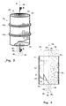
- An electrical unit that may include ring electrodes or a spiral electrode (not shown in Fig. 1), will establish an electrical field (E) in the chamber 12 that is radially oriented and will, therefore, establish crossed electric and magnetic fields (E x B) in the chamber 12.
- the configuration of the chamber 12 is such that a 2 (r 2 ) is larger than a 3 (r 3 ).
- the magnetic field strength decreases as the corresponding radial distance increases.
- the magnetic field strength B 3 at the position z designated 3 is larger than the magnetic field strength B 2 , at the position z designated 2.
- FIG. 3 Another embodiment for a filter in accordance with the present invention is shown in Fig. 3 and is generally designated 40.
- the filter 40 has a substantially cylindrical shaped chamber 42 that is centered on the longitudinal axis 20 and is defined by a wall 44.
- there are a plurality of magnetic coils 46 that establish a substantially uniform magnetic field B which extends through the chamber 42 in a direction that is generally parallel to the axis 20.
- An electric field, E is created inside the chamber which crosses with the magnetic field, B, to establish crossed electric and magnetic fields (E x B) in the chamber 42.
- the electric field, E can be generated in a manner well known in the pertinent art using either a ring electrode unit 48 or a spiral electrode 50. The particulars of the electric field, E, are perhaps best appreciated with reference to Fig. 4.
- the electric field, E is established between the wall 44, which is at ground, and a positive voltage, V ctr , that extends along the axis 20.
- the electric field, E has a profile in the chamber 42 that increases outwardly from the axis 20 through a radial distance "a 2 " (r 2 ) at a rate of change 52.
- the electric field then continues to increase outwardly from the radial distance "a 2 " (r 2 ) to a radial distance "a 3 " (r 3 ) at a rate of change 54.
- the rate of change 52 is greater than the rate of change 54.
- the voltages, V ctr on the axis and V 2 at r 2 are externally
- the particles M 1 will be confined to travel on trajectories in the chamber 42 which do not travel radially more than a distance "a 2 " (r 2 ) from the axis 20.
- the particles M 1 are ejected from the chamber 42 into a first region 56 that extends generally along the axis 20.
- the particles M 2 and M 3 are not so confined and will have trajectories that take them into a second region 58 that surrounds the first region 56.
- the second region 58 is outside the first region 56 at more than the distance "a 2 " (r 2 ) from the axis 20.
- the expression for cut-off mass M c3 e(r 3 2 -r 2 2 )B 2 /(8*V 2 ) can be used to confine particles M 2 in the second region 58, but not the particles M 3 . Instead, the particles M 3 are able to follow trajectories into a third region. In this case, the third region is actually the wall 44. Accordingly, as shown in Fig. 4, when the multi-species plasma 24 is introduced into the chamber 42, the particles M 1 will be confined in the chamber 42 for ejection therefrom into the first region 56. The particles M 2 , on the other hand are allowed to proceed with the particles M 3 beyond the first region 56.
Landscapes
- Chemical & Material Sciences (AREA)
- Analytical Chemistry (AREA)
- Electron Tubes For Measurement (AREA)
- Plasma Technology (AREA)
- Other Investigation Or Analysis Of Materials By Electrical Means (AREA)
- Physical Or Chemical Processes And Apparatus (AREA)
Applications Claiming Priority (2)
| Application Number | Priority Date | Filing Date | Title |
|---|---|---|---|
| US643204 | 1996-05-02 | ||
| US09/643,204 US6293406B1 (en) | 2000-08-21 | 2000-08-21 | Multi-mass filter |
Publications (2)
| Publication Number | Publication Date |
|---|---|
| EP1220286A2 true EP1220286A2 (fr) | 2002-07-03 |
| EP1220286A3 EP1220286A3 (fr) | 2003-04-02 |
Family
ID=24579795
Family Applications (1)
| Application Number | Title | Priority Date | Filing Date |
|---|---|---|---|
| EP01202935A Withdrawn EP1220286A3 (fr) | 2000-08-21 | 2001-08-02 | Filtre de masse mutiple |
Country Status (3)
| Country | Link |
|---|---|
| US (2) | US6293406B1 (fr) |
| EP (1) | EP1220286A3 (fr) |
| JP (1) | JP3738207B2 (fr) |
Families Citing this family (10)
| Publication number | Priority date | Publication date | Assignee | Title |
|---|---|---|---|---|
| GB0025016D0 (en) | 2000-10-12 | 2000-11-29 | Micromass Ltd | Method nad apparatus for mass spectrometry |
| JP4854842B2 (ja) * | 2000-10-20 | 2012-01-18 | 独立行政法人科学技術振興機構 | 粒子の制御方法 |
| US6773558B2 (en) * | 2002-10-15 | 2004-08-10 | Archimedes Technology Group, Inc. | Fluorine generator |
| KR100766093B1 (ko) * | 2005-07-13 | 2007-10-11 | 삼성전자주식회사 | 플라즈마를 분리 가속시키는 중성 빔 에칭 장치 |
| US7504031B2 (en) * | 2005-08-16 | 2009-03-17 | Dunlap Henry R | Ion separation and gas generation |
| US7223335B2 (en) * | 2005-08-16 | 2007-05-29 | Dunlap Henry R | Ion separation |
| US20070095726A1 (en) * | 2005-10-28 | 2007-05-03 | Tihiro Ohkawa | Chafftron |
| CN104520453A (zh) | 2011-11-10 | 2015-04-15 | 先进磁工艺股份有限公司 | 用于分离的磁电-等离子体分离器及方法 |
| EP2792412A4 (fr) * | 2011-12-12 | 2016-04-20 | Ube Industries | Procédé de séparation d'un mélange et dispositif de séparation |
| US20140141619A1 (en) * | 2012-11-19 | 2014-05-22 | Tokyo Electron Limited | Capacitively coupled plasma equipment with uniform plasma density |
Family Cites Families (12)
| Publication number | Priority date | Publication date | Assignee | Title |
|---|---|---|---|---|
| SE338962B (fr) | 1970-06-04 | 1971-09-27 | B Lehnert | |
| US3942975A (en) * | 1971-08-18 | 1976-03-09 | The Boeing Company | Method and apparatus for reducing matter to constituent elements and separating one of the elements from the other elements |
| US3845300A (en) * | 1973-04-18 | 1974-10-29 | Atomic Energy Commission | Apparatus and method for magnetoplasmadynamic isotope separation |
| US4107524A (en) * | 1975-12-04 | 1978-08-15 | Book David L | High atomic weight isotope separator |
| US4093856A (en) * | 1976-06-09 | 1978-06-06 | Trw Inc. | Method of and apparatus for the electrostatic excitation of ions |
| FR2363364A1 (fr) * | 1976-09-07 | 1978-03-31 | Thomson Csf | Procede de separation isotopique et installation pour sa mise en oeuvre |
| US4213043A (en) * | 1977-07-20 | 1980-07-15 | Trw Inc. | Method for flowing a large volume of plasma through an excitation region |
| FR2705584B1 (fr) * | 1993-05-26 | 1995-06-30 | Commissariat Energie Atomique | Dispositif de séparation isotopique par résonance cyclotronique ionique. |
| US5681434A (en) | 1996-03-07 | 1997-10-28 | Eastlund; Bernard John | Method and apparatus for ionizing all the elements in a complex substance such as radioactive waste and separating some of the elements from the other elements |
| GB9704077D0 (en) | 1996-03-15 | 1997-04-16 | British Nuclear Fuels Plc | Improvements in and relating to processing |
| US5868909A (en) | 1997-04-21 | 1999-02-09 | Eastlund; Bernard John | Method and apparatus for improving the energy efficiency for separating the elements in a complex substance such as radioactive waste with a large volume plasma processor |
| US6096220A (en) | 1998-11-16 | 2000-08-01 | Archimedes Technology Group, Inc. | Plasma mass filter |
-
2000
- 2000-08-21 US US09/643,204 patent/US6293406B1/en not_active Expired - Fee Related
-
2001
- 2001-05-17 US US09/860,161 patent/US6386374B1/en not_active Expired - Fee Related
- 2001-08-02 EP EP01202935A patent/EP1220286A3/fr not_active Withdrawn
- 2001-08-20 JP JP2001249300A patent/JP3738207B2/ja not_active Expired - Fee Related
Also Published As
| Publication number | Publication date |
|---|---|
| US6386374B1 (en) | 2002-05-14 |
| EP1220286A3 (fr) | 2003-04-02 |
| US6293406B1 (en) | 2001-09-25 |
| JP3738207B2 (ja) | 2006-01-25 |
| US20020020657A1 (en) | 2002-02-21 |
| JP2002177814A (ja) | 2002-06-25 |
Similar Documents
| Publication | Publication Date | Title |
|---|---|---|
| JP3492960B2 (ja) | プラズマ質量フィルタ | |
| US6322706B1 (en) | Radial plasma mass filter | |
| US6251281B1 (en) | Negative ion filter | |
| EP1220293B1 (fr) | Filtre de masse en tandem pour plasma | |
| US6293406B1 (en) | Multi-mass filter | |
| CA2313756C (fr) | Filtre au plasma permettant la separation des particules en fonction de leur masse | |
| US6726844B2 (en) | Isotope separator | |
| US6730231B2 (en) | Plasma mass filter with axially opposed plasma injectors | |
| US6217776B1 (en) | Centrifugal filter for multi-species plasma | |
| US6787044B1 (en) | High frequency wave heated plasma mass filter | |
| US6956217B2 (en) | Mass separator with controlled input | |
| US6723248B2 (en) | High throughput plasma mass filter | |
| US6521888B1 (en) | Inverted orbit filter | |
| EP1351273B1 (fr) | Spectromètre de masse pour plasma à bande interdite | |
| US6939469B2 (en) | Band gap mass filter with induced azimuthal electric field | |
| EP1220289A2 (fr) | Filtre de masse à plasma |
Legal Events
| Date | Code | Title | Description |
|---|---|---|---|
| PUAI | Public reference made under article 153(3) epc to a published international application that has entered the european phase |
Free format text: ORIGINAL CODE: 0009012 |
|
| AK | Designated contracting states |
Kind code of ref document: A2 Designated state(s): AT BE CH CY DE DK ES FI FR GB GR IE IT LI LU MC NL PT SE TR |
|
| AX | Request for extension of the european patent |
Free format text: AL;LT;LV;MK;RO;SI |
|
| PUAL | Search report despatched |
Free format text: ORIGINAL CODE: 0009013 |
|
| AK | Designated contracting states |
Kind code of ref document: A3 Designated state(s): AT BE CH CY DE DK ES FI FR GB GR IE IT LI LU MC NL PT SE TR Designated state(s): AT BE CH CY DE DK ES FI FR GB GR IE IT LI LU MC NL PT SE TR |
|
| AX | Request for extension of the european patent |
Extension state: AL LT LV MK RO SI |
|
| RIC1 | Information provided on ipc code assigned before grant |
Ipc: 7B 01D 59/48 B Ipc: 7H 01J 37/32 B Ipc: 7H 01J 49/28 A |
|
| 17P | Request for examination filed |
Effective date: 20030718 |
|
| AKX | Designation fees paid |
Designated state(s): DE FR GB |
|
| RAP1 | Party data changed (applicant data changed or rights of an application transferred) |
Owner name: ARCHIMEDES OPERATING, LLC |
|
| STAA | Information on the status of an ep patent application or granted ep patent |
Free format text: STATUS: THE APPLICATION HAS BEEN WITHDRAWN |
|
| 18W | Application withdrawn |
Effective date: 20060505 |