EP1220416A2 - Vorrichtung zur Stromerzeugung aus einem Drehstromnetz, mit einem bordseitigen Alternator - Google Patents
Vorrichtung zur Stromerzeugung aus einem Drehstromnetz, mit einem bordseitigen Alternator Download PDFInfo
- Publication number
- EP1220416A2 EP1220416A2 EP01403120A EP01403120A EP1220416A2 EP 1220416 A2 EP1220416 A2 EP 1220416A2 EP 01403120 A EP01403120 A EP 01403120A EP 01403120 A EP01403120 A EP 01403120A EP 1220416 A2 EP1220416 A2 EP 1220416A2
- Authority
- EP
- European Patent Office
- Prior art keywords
- alternator
- inductance
- switching
- windings
- phase
- Prior art date
- Legal status (The legal status is an assumption and is not a legal conclusion. Google has not performed a legal analysis and makes no representation as to the accuracy of the status listed.)
- Withdrawn
Links
Images

Classifications
-
- H—ELECTRICITY
- H02—GENERATION; CONVERSION OR DISTRIBUTION OF ELECTRIC POWER
- H02K—DYNAMO-ELECTRIC MACHINES
- H02K19/00—Synchronous motors or generators
- H02K19/16—Synchronous generators
- H02K19/36—Structural association of synchronous generators with auxiliary electric devices influencing the characteristic of the generator or controlling the generator, e.g. with impedances or switches
-
- H—ELECTRICITY
- H02—GENERATION; CONVERSION OR DISTRIBUTION OF ELECTRIC POWER
- H02K—DYNAMO-ELECTRIC MACHINES
- H02K19/00—Synchronous motors or generators
- H02K19/16—Synchronous generators
- H02K19/36—Structural association of synchronous generators with auxiliary electric devices influencing the characteristic of the generator or controlling the generator, e.g. with impedances or switches
- H02K19/365—Structural association of synchronous generators with auxiliary electric devices influencing the characteristic of the generator or controlling the generator, e.g. with impedances or switches with a voltage regulator
-
- H—ELECTRICITY
- H02—GENERATION; CONVERSION OR DISTRIBUTION OF ELECTRIC POWER
- H02M—APPARATUS FOR CONVERSION BETWEEN AC AND AC, BETWEEN AC AND DC, OR BETWEEN DC AND DC, AND FOR USE WITH MAINS OR SIMILAR POWER SUPPLY SYSTEMS; CONVERSION OF DC OR AC INPUT POWER INTO SURGE OUTPUT POWER; CONTROL OR REGULATION THEREOF
- H02M7/00—Conversion of AC power input into DC power output; Conversion of DC power input into AC power output
- H02M7/02—Conversion of AC power input into DC power output without possibility of reversal
- H02M7/04—Conversion of AC power input into DC power output without possibility of reversal by static converters
- H02M7/12—Conversion of AC power input into DC power output without possibility of reversal by static converters using discharge tubes with control electrode or semiconductor devices with control electrode
- H02M7/21—Conversion of AC power input into DC power output without possibility of reversal by static converters using discharge tubes with control electrode or semiconductor devices with control electrode using devices of a triode or transistor type requiring continuous application of a control signal
- H02M7/217—Conversion of AC power input into DC power output without possibility of reversal by static converters using discharge tubes with control electrode or semiconductor devices with control electrode using devices of a triode or transistor type requiring continuous application of a control signal using semiconductor devices only
-
- H—ELECTRICITY
- H02—GENERATION; CONVERSION OR DISTRIBUTION OF ELECTRIC POWER
- H02P—CONTROL OR REGULATION OF ELECTRIC MOTORS, ELECTRIC GENERATORS OR DYNAMO-ELECTRIC CONVERTERS; CONTROLLING TRANSFORMERS, REACTORS OR CHOKE COILS
- H02P9/00—Arrangements for controlling electric generators for the purpose of obtaining a desired output
- H02P9/14—Arrangements for controlling electric generators for the purpose of obtaining a desired output by variation of field
- H02P9/26—Arrangements for controlling electric generators for the purpose of obtaining a desired output by variation of field using discharge tubes or semiconductor devices
- H02P9/30—Arrangements for controlling electric generators for the purpose of obtaining a desired output by variation of field using discharge tubes or semiconductor devices using semiconductor devices
- H02P9/305—Arrangements for controlling electric generators for the purpose of obtaining a desired output by variation of field using discharge tubes or semiconductor devices using semiconductor devices controlling voltage
-
- H—ELECTRICITY
- H02—GENERATION; CONVERSION OR DISTRIBUTION OF ELECTRIC POWER
- H02M—APPARATUS FOR CONVERSION BETWEEN AC AND AC, BETWEEN AC AND DC, OR BETWEEN DC AND DC, AND FOR USE WITH MAINS OR SIMILAR POWER SUPPLY SYSTEMS; CONVERSION OF DC OR AC INPUT POWER INTO SURGE OUTPUT POWER; CONTROL OR REGULATION THEREOF
- H02M3/00—Conversion of DC power input into DC power output
- H02M3/02—Conversion of DC power input into DC power output without intermediate conversion into AC
- H02M3/04—Conversion of DC power input into DC power output without intermediate conversion into AC by static converters
- H02M3/10—Conversion of DC power input into DC power output without intermediate conversion into AC by static converters using discharge tubes with control electrode or semiconductor devices with control electrode
- H02M3/145—Conversion of DC power input into DC power output without intermediate conversion into AC by static converters using discharge tubes with control electrode or semiconductor devices with control electrode using devices of a triode or transistor type requiring continuous application of a control signal
- H02M3/155—Conversion of DC power input into DC power output without intermediate conversion into AC by static converters using discharge tubes with control electrode or semiconductor devices with control electrode using devices of a triode or transistor type requiring continuous application of a control signal using semiconductor devices only
- H02M3/1552—Boost converters exploiting the leakage inductance of a transformer or of an alternator as boost inductor
Definitions
- the present invention relates to the production of electricity on board vehicles or containers, for example.
- Patents US-A-5,793,625 and US-A-4,825,139 describe other devices whose chopper uses the alternator's own inductance.
- Installations supplied with current by means of the production device of electricity present on board the vehicle or container are for example installations refrigeration.
- the invention aims to meet this need.
- alternator windings could be connected directly to the network to supply the rectifier.
- the device can supply a regulator making it possible to make vary both the frequency f and the voltage U, for example keeping U / f constant.
- a 5.5 kW motor at 400 V and 50 Hz can see for example its power go to 6.6 kW at 460 V and 60 Hz and to 7.5 kW at 500 V and 70 Hz.
- an alternator having eight poles is used and the element of switching operates with a switching frequency between 3 and 15 kHz, from preferably less than 8 kHz and more preferably approximately 7.5 kHz.
- the applicant company has found that the device according to the invention at such a switching frequency with overall efficiency satisfactory.
- the inductance in% eigen per phase of the alternator defined by the formula L ⁇ I N / V o , where L is the eigen inductance of the alternator, ⁇ the pulsation, I N the nominal current at a speed given, for example 1,500 rpm, and V o the no- load voltage of the alternator at said speed is between 15 and 40%, preferably between 20 and 30%.
- the inductance per phase of the alternator is less than or equal to 2 mH, preferably less than or equal to 1.5 mH, this which corresponds to an inductance in% less than 30%.
- the inductance per phase of the alternator is greater than or equal to 1 mH, which corresponds to an inductance in% greater than 20%.
- the alternator is with permanent magnets.
- the chopper is downstream of the rectifier, which allows use only one transistor, for example an IGBT transistor.
- This single transistor can be easily cooled by circulation of a liquid, whereas in known devices whose choppers include several transistors, this cooling is made more difficult by the number of transistors, which cannot be mounted on a common cooler without causing insulation problems.
- the switching frequency is constant, which simplifies control electronics.
- the chopper can be connected directly to the rectifier, without a coil between the of them.
- the chopper supplies at least one inverter controlled by a control circuit receiving information representative of the rotational speed of the alternator rotor.
- control circuit can take into account the power available for the devices connected to the inverter, and control their operation by result.
- the device makes it possible, for example, to supply electricity to a refrigeration comprising at least one motor.
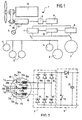
- the energy chain 1 shown in Figure 1 has different devices 2 to 5 driven by electric motors, such as motor-fans or pumps.
- Two operating modes are possible, namely a autonomous operation in which the energy is supplied by a heat engine 12, by example a diesel engine whose rotation speed is likely to vary, typically between 600 and 3,600 rpm, and a non-autonomous operating mode, in which the heat engine 12 is stopped and the energy is supplied by a three-phase electrical network R, for example 400 V / 50 Hz or 460 V / 60 Hz, or other.
- a heat engine 12 by example a diesel engine whose rotation speed is likely to vary, typically between 600 and 3,600 rpm
- a non-autonomous operating mode in which the heat engine 12 is stopped and the energy is supplied by a three-phase electrical network R, for example 400 V / 50 Hz or 460 V / 60 Hz, or other.
- Devices 2 to 5 are supplied with three-phase current of constant frequency or variable by two inverters 7 and 8 themselves supplied with direct current by a booster chopper 9 connected to a rectifier 6, itself connected to an alternator 10 including the rotor can be rotated, via a transmission 11, by the motor thermal 12.
- the transmission 11 makes it possible to multiply for example by a factor 2 or 3 the rotational speed of the rotor, so that the alternator 10 can be driven at a speed of rotation for example between 1,500 rpm when the engine is idling and at more than 5,000 rpm when the engine 12 is running at high speed.
- the chain 1 comprises a control circuit 13 receiving in particular a information representative of the speed of rotation of the rotor of the alternator 10, in order to control the various user devices 2 to 5 depending on the power available at inverters 7 and 8.
- the alternator 10 is three-phase and has three windings 10a, 10b and 10c, each with its own inductance L.
- the three windings 10a, 10b and 10c are each connected to a terminal 31a, 31b and 31c of a switch 30 having switches 35a, 35b and 35c controlled simultaneously and each associated with a coil 10a, 10b and 10c.
- Terminals 31a, 31b and 31c can be selectively connected by the switches 35a, 35b and 35c either at terminals 32a, 32b and 32c respectively, or at terminals 33a, 33b and 33c respectively, depending on the operating mode selected.
- the terminals 32a, 32b and 32c are connected to a midpoint 34 while the terminals 33a, 33b and 33c are respectively connected to the three phases L 1 , L 2 and L 3 of the three-phase network R.
- the switch 30 can be with mechanical switches 35a, 35b and 35c or electronic and be operated manually or automatically and allows switching to choice of autonomous operating mode to non-autonomous mode, and vice-versa.
- the switching is lockable in each of its positions, moving from one position to another requiring a key, for example.
- the windings 10a, 10b and 10c are connected in star by the midpoint 34 and in non-autonomous operating mode, the rectifier 6 is supplied through the windings 10a, 10b and 10c by the network R, without addition of external rectifier bridge.
- the power supplied may be constant, being regulated by the chopper 9.
- the rectifier 6 comprises, in a manner known per se, six diodes 6a to 6f arranged to deliver a rectified voltage.
- the booster chopper 9 comprises an electronic switch 15 capable of short-circuiting the output of rectifier 6, a diode 16 downstream of switch 15 and a storage capacitor 17 at output.
- the chopper 9 is of the parallel chopper type and uses the own inductance of the alternator 10 for storing reactive energy.
- the electronic switch 15 is consisting of a single IGBT transistor, controlled by an electronic control circuit when switching at a constant switching frequency, this electronic circuit of order being carried out in a conventional manner and not being represented for the sake of clarity of the drawing.
- the electronic control circuit is advantageously arranged so as to modify the duty cycle of the control signal of the electronic switch 15 by function of the voltage at the output of the lifting chopper 9, so as to regulate this voltage at a setpoint.
- the switching frequency is 7.5 kHz.
- FIG. 3 and 4 show the alternator 10 in isolation.
- the alternator 10 comprises a casing 11 intended to be cooled by a liquid, provided for this purpose with connection nozzles 12 and 13 to a water circuit of cooling.
- the alternator 10 is in the embodiment described a three-phase alternator comprising eight poles, the three windings 10a, 10b and 10c being each wound so conventional in notches of the stator 25 of the alternator 10, the latter comprising a total of forty-eight notches.
- the rotor 24 comprises, in the embodiment described, magnets permanent, four in number per pole.
- magnets with a fairly low residual field are used but with good coercivity (B r close to 1.1 T nominal at 20 ° C and H cj close to 900 kA / m nominal at 150 ° C).
- the thickness of the magnets used is close to 5 mm, for example.
- stator sheets are made of silicon alloy, the length of the irons being of the order of 115 mm.
- the number of turns is equal to 20.
- the bun heads 20 formed by the wires of the windings outside the stator irons protruding from part and other of these are embedded in a conductive resin 21, which allows including reducing losses.
- the power of the device is of the order of 10 kW and the own inductance L per phase of the alternator is around 1.3 mH.
- the switching frequency of the electronic switch 15 and the value of the specific inductance of each phase of the alternator allows for both losses by switching in electronic switch 15 and a level of harmonics compatible with the desired performance.
- the value of the own inductance per phase which is chosen allows on the one hand to keep the harmonics at a relatively low level taking into account the frequency of switching the electronic switch and secondly to prevent the voltage drop due to the encroachment phenomenon proves detrimental to the output power of the lifting chopper.
- the inductance in% is chosen between 20 and 40%, preferably being included between 20 and 30%.
- Coating of the alternator stator bun heads in a resin conductive is not essential but has the advantage of facilitating cooling windings and increase the mass power of the alternator.
- alternators 10 we can place several alternators 10 side by side, driven by an axis common, in order to increase the power delivered.
- a single rectifier can be used, that the alternator is rotated or the engine is stopped.
- the alternator power supply enables the alternator to be stalled in position and to limit losses and efforts.
- the weight of on-board equipment can remain relatively low.
Landscapes
- Engineering & Computer Science (AREA)
- Power Engineering (AREA)
- Control Of Eletrric Generators (AREA)
Applications Claiming Priority (2)
| Application Number | Priority Date | Filing Date | Title |
|---|---|---|---|
| FR0016574A FR2818458B1 (fr) | 2000-12-19 | 2000-12-19 | Dispositif de production d'electricite a partir du reseau triphase, comprenant un alternateur embarque |
| FR0016574 | 2000-12-19 |
Publications (2)
| Publication Number | Publication Date |
|---|---|
| EP1220416A2 true EP1220416A2 (de) | 2002-07-03 |
| EP1220416A3 EP1220416A3 (de) | 2005-01-05 |
Family
ID=8857859
Family Applications (1)
| Application Number | Title | Priority Date | Filing Date |
|---|---|---|---|
| EP01403120A Withdrawn EP1220416A3 (de) | 2000-12-19 | 2001-12-05 | Vorrichtung zur Stromerzeugung aus einem Drehstromnetz, mit einem bordseitigen Alternator |
Country Status (4)
| Country | Link |
|---|---|
| US (1) | US6480404B2 (de) |
| EP (1) | EP1220416A3 (de) |
| JP (1) | JP4370068B2 (de) |
| FR (1) | FR2818458B1 (de) |
Families Citing this family (11)
| Publication number | Priority date | Publication date | Assignee | Title |
|---|---|---|---|---|
| FR2797535B1 (fr) * | 1999-08-09 | 2001-10-12 | Leroy Somer | Dispositif de production d'electricite |
| US7460918B2 (en) * | 2004-06-10 | 2008-12-02 | Moteurs Leroy-Somer | Devices and methods for updating the programming of a system for controlling an electric rotary machine |
| US8073469B2 (en) | 2005-01-31 | 2011-12-06 | Jasper Wireless, Inc. | Paging for non-real-time communications wireless networks |
| JP5682996B2 (ja) * | 2010-02-04 | 2015-03-11 | インターナショナル・ビジネス・マシーンズ・コーポレーションInternational Business Machines Corporation | クライアントプログラム、端末、サーバ装置、サーバプログラム、システムおよび方法 |
| FR2993506B1 (fr) * | 2012-07-19 | 2015-06-05 | Leroy Somer Moteurs | Ensemble comportant un generateur et des moteurs electriques, pour un systeme de climatisation ou de refrigeration de vehicule. |
| EP2782225A1 (de) * | 2013-03-19 | 2014-09-24 | Siemens Aktiengesellschaft | Sternpunkt eines Generators |
| JP6356796B2 (ja) | 2013-07-19 | 2018-07-11 | グラコ ミネソタ インコーポレーテッド | 多点シール潤滑装置 |
| FR3033458B1 (fr) | 2015-03-05 | 2018-06-15 | Moteurs Leroy-Somer | Ensemble electromecanique comportant un alternateur |
| US9973129B2 (en) | 2015-06-12 | 2018-05-15 | Trane International Inc. | HVAC components having a variable speed drive with optimized power factor correction |
| CN107546890B (zh) | 2016-06-28 | 2021-07-16 | 特灵国际有限公司 | 谐波分流的电机、方法、ac电机系统及可变速驱动系统 |
| US10826357B2 (en) | 2017-06-28 | 2020-11-03 | Trane International Inc. | Harmonic shunting electric motor with faceted shaft for improved torque transmission |
Family Cites Families (13)
| Publication number | Priority date | Publication date | Assignee | Title |
|---|---|---|---|---|
| US3697850A (en) * | 1970-12-31 | 1972-10-10 | Westinghouse Electric Corp | Battery charger connected in series with an alternating current load circuit via a rectifier |
| US3745366A (en) * | 1971-11-04 | 1973-07-10 | Gen Electric | Dual source auxiliary power supply |
| US4143280A (en) * | 1977-07-01 | 1979-03-06 | General Electric Company | Control system for a tertiary winding self-excited generator |
| GB2015212B (en) * | 1978-01-24 | 1982-08-18 | Nada Electronics Ltd | Voltage regulation |
| FR2601207B1 (fr) * | 1986-07-04 | 1988-10-21 | Valeo | Ensemble d'alimentation electrique, notamment pour vehicule automobile et machine electrique tournante pour un tel ensemble |
| JPH0630505A (ja) * | 1992-01-31 | 1994-02-04 | Fuji Electric Co Ltd | 電気自動車の電気システム |
| US5606232A (en) * | 1994-11-22 | 1997-02-25 | Nidec Corporation | DC on line AC brushless motor |
| JP3333833B2 (ja) * | 1995-08-16 | 2002-10-15 | いすゞ自動車株式会社 | 自動車用電力変換装置 |
| WO1998025014A2 (en) * | 1996-12-03 | 1998-06-11 | Elliott Energy Systems, Inc. | Electrical system for turbine/alternator on common shaft |
| US5793625A (en) * | 1997-01-24 | 1998-08-11 | Baker Hughes Incorporated | Boost converter regulated alternator |
| US5942818A (en) * | 1998-02-06 | 1999-08-24 | Isuzu Ceramics Research Institute Co., Ltd. | Control apparatus for engine-driven permanent magnet type synchronous generators |
| JP2000283622A (ja) * | 1999-03-29 | 2000-10-13 | Toshiba Kyaria Kk | 冷凍車用冷凍装置 |
| JP4289718B2 (ja) * | 1999-04-20 | 2009-07-01 | 三洋電機株式会社 | 電源装置 |
-
2000
- 2000-12-19 FR FR0016574A patent/FR2818458B1/fr not_active Expired - Fee Related
-
2001
- 2001-12-05 EP EP01403120A patent/EP1220416A3/de not_active Withdrawn
- 2001-12-13 US US10/023,202 patent/US6480404B2/en not_active Expired - Fee Related
- 2001-12-19 JP JP2001385847A patent/JP4370068B2/ja not_active Expired - Fee Related
Also Published As
| Publication number | Publication date |
|---|---|
| EP1220416A3 (de) | 2005-01-05 |
| JP4370068B2 (ja) | 2009-11-25 |
| US6480404B2 (en) | 2002-11-12 |
| US20020105819A1 (en) | 2002-08-08 |
| FR2818458A1 (fr) | 2002-06-21 |
| JP2002233191A (ja) | 2002-08-16 |
| FR2818458B1 (fr) | 2003-03-28 |
Similar Documents
| Publication | Publication Date | Title |
|---|---|---|
| EP0792769B1 (de) | Kraftfahrzeuggenerator, arbeitend als Generator und als elektrischer Motor, und Regelverfahren für einen solchen Generator | |
| FR2601207A1 (fr) | Ensemble d'alimentation electrique, notamment pour vehicule automobile et machine electrique tournante pour un tel ensemble | |
| FR2843842A1 (fr) | Dispositif de commande d'une machine electrique tournante pour vehicule | |
| FR2769770A1 (fr) | Moyen de regulation d'un generateur electrique | |
| FR2474781A1 (fr) | Groupe convertisseur comportant un moteur triphase et un generateur synchrone | |
| FR2766990A1 (fr) | Mode de couplage pour un alternateur triphase d'un vehicule automobile et procede d'excitation de mode de couplage | |
| FR2463533A1 (fr) | Machine electrique a vitesse variable et a densite reglee du flux magnetique | |
| WO2003088471A2 (fr) | Agencement pour la mise en œuvre d'une machine electrique tournante polyphasee et reversible associee a un moteur thermique d'un vehicule automobile | |
| EP1515426A1 (de) | Elektrizitätserzeugungssystem mit fester Frequenz und Verfahren zur Steuerung desselben | |
| EP1220416A2 (de) | Vorrichtung zur Stromerzeugung aus einem Drehstromnetz, mit einem bordseitigen Alternator | |
| EP0783201B1 (de) | Elektromotor des Synchrontyps mit Permanentmagneten und mit einem solchen Motor ausgestattetes Fahrzeug | |
| EP2095498B1 (de) | Stromversorgungssystem für kraftfahrzeug mit einer energiespeichermittel-vorladeeinrichtung | |
| EP2656487A2 (de) | Spannungsregler für eine elektrische drehmaschine, lager für eine solche maschine mit einer solchen vorrichtung und solche maschine mit einem lager | |
| EP1076411B1 (de) | Vorrichtung zur Produktion von Elektrizität | |
| EP1331716B1 (de) | Elektrisches Energieversorgungsystem eines Kraftfahrzeuges | |
| EP1112896B1 (de) | Leistungerzeugungsystem für ein Doppelspannungsnetz | |
| EP1673854B1 (de) | Vorrichtung für synchrongleichrichtung und zugehörige synchronmaschine | |
| WO2016079401A1 (fr) | Systeme d'alimentation electrique d'un vehicule automobile et module electronique de commande correspondant | |
| EP0054446B1 (de) | Elektrischer Asynchronmotor, Einrichtung zum Regeln der Speisung eines solchen Motors und Umwälzantrieb mit einem solchen Motor | |
| FR2842041A1 (fr) | Module de controle et de puissance d'un alterno-demarreur integrable | |
| FR2843841A1 (fr) | Dispositif et procede de commande d'une machine electrique tournante pour vehicule | |
| EP1524753A1 (de) | Einheit bestehend aus einer Lichtmaschine und einer Motorankupplungsvorrichtung, insbesondere Kraftfahrzeugsmotor | |
| WO2018051013A1 (fr) | Systeme de transfert de puissance electrique | |
| FR3056833B1 (fr) | Machine electrique tournante equipee de deux bobinages | |
| FR2474782A1 (fr) | Groupe convertisseur comportant un moteur triphase et un generateur synchrone |
Legal Events
| Date | Code | Title | Description |
|---|---|---|---|
| PUAI | Public reference made under article 153(3) epc to a published international application that has entered the european phase |
Free format text: ORIGINAL CODE: 0009012 |
|
| AK | Designated contracting states |
Kind code of ref document: A2 Designated state(s): AT BE CH CY DE DK ES FI FR GB GR IE IT LI LU MC NL PT SE TR |
|
| AX | Request for extension of the european patent |
Free format text: AL;LT;LV;MK;RO;SI |
|
| PUAL | Search report despatched |
Free format text: ORIGINAL CODE: 0009013 |
|
| AK | Designated contracting states |
Kind code of ref document: A3 Designated state(s): AT BE CH CY DE DK ES FI FR GB GR IE IT LI LU MC NL PT SE TR |
|
| AX | Request for extension of the european patent |
Extension state: AL LT LV MK RO SI |
|
| RIC1 | Information provided on ipc code assigned before grant |
Ipc: 7H 02M 7/217 B Ipc: 7H 02J 7/14 B Ipc: 7H 02J 7/02 A |
|
| 17P | Request for examination filed |
Effective date: 20050622 |
|
| AKX | Designation fees paid |
Designated state(s): AT BE CH CY DE DK ES FI FR GB GR IE IT LI LU MC NL PT SE TR |
|
| 17Q | First examination report despatched |
Effective date: 20130121 |
|
| STAA | Information on the status of an ep patent application or granted ep patent |
Free format text: STATUS: THE APPLICATION IS DEEMED TO BE WITHDRAWN |
|
| 18D | Application deemed to be withdrawn |
Effective date: 20130801 |