EP1220436A2 - Anordnung mit einer elektronischen Laststeuerungsvorrichtung und einer Stromversorgungseinheit für solche Vorrichtung - Google Patents
Anordnung mit einer elektronischen Laststeuerungsvorrichtung und einer Stromversorgungseinheit für solche Vorrichtung Download PDFInfo
- Publication number
- EP1220436A2 EP1220436A2 EP01403315A EP01403315A EP1220436A2 EP 1220436 A2 EP1220436 A2 EP 1220436A2 EP 01403315 A EP01403315 A EP 01403315A EP 01403315 A EP01403315 A EP 01403315A EP 1220436 A2 EP1220436 A2 EP 1220436A2
- Authority
- EP
- European Patent Office
- Prior art keywords
- capacitor
- transistor
- voltage
- charge
- switch member
- Prior art date
- Legal status (The legal status is an assumption and is not a legal conclusion. Google has not performed a legal analysis and makes no representation as to the accuracy of the status listed.)
- Withdrawn
Links
Images


Classifications
-
- H—ELECTRICITY
- H02—GENERATION; CONVERSION OR DISTRIBUTION OF ELECTRIC POWER
- H02M—APPARATUS FOR CONVERSION BETWEEN AC AND AC, BETWEEN AC AND DC, OR BETWEEN DC AND DC, AND FOR USE WITH MAINS OR SIMILAR POWER SUPPLY SYSTEMS; CONVERSION OF DC OR AC INPUT POWER INTO SURGE OUTPUT POWER; CONTROL OR REGULATION THEREOF
- H02M5/00—Conversion of AC power input into AC power output, e.g. for change of voltage, for change of frequency, for change of number of phases
- H02M5/02—Conversion of AC power input into AC power output, e.g. for change of voltage, for change of frequency, for change of number of phases without intermediate conversion into DC
- H02M5/04—Conversion of AC power input into AC power output, e.g. for change of voltage, for change of frequency, for change of number of phases without intermediate conversion into DC by static converters
- H02M5/22—Conversion of AC power input into AC power output, e.g. for change of voltage, for change of frequency, for change of number of phases without intermediate conversion into DC by static converters using discharge tubes with control electrode or semiconductor devices with control electrode
- H02M5/275—Conversion of AC power input into AC power output, e.g. for change of voltage, for change of frequency, for change of number of phases without intermediate conversion into DC by static converters using discharge tubes with control electrode or semiconductor devices with control electrode using devices of a triode or transistor type requiring continuous application of a control signal
- H02M5/293—Conversion of AC power input into AC power output, e.g. for change of voltage, for change of frequency, for change of number of phases without intermediate conversion into DC by static converters using discharge tubes with control electrode or semiconductor devices with control electrode using devices of a triode or transistor type requiring continuous application of a control signal using semiconductor devices only
-
- H—ELECTRICITY
- H02—GENERATION; CONVERSION OR DISTRIBUTION OF ELECTRIC POWER
- H02M—APPARATUS FOR CONVERSION BETWEEN AC AND AC, BETWEEN AC AND DC, OR BETWEEN DC AND DC, AND FOR USE WITH MAINS OR SIMILAR POWER SUPPLY SYSTEMS; CONVERSION OF DC OR AC INPUT POWER INTO SURGE OUTPUT POWER; CONTROL OR REGULATION THEREOF
- H02M1/00—Details of apparatus for conversion
- H02M1/0003—Details of control, feedback or regulation circuits
- H02M1/0006—Arrangements for supplying an adequate voltage to the control circuit of converters
Definitions
- the invention relates to devices for controlling an electric charge supplied with alternating current and more particularly devices of this type having an electronic load control device, which device must be supplied with direct current.
- Devices equipped with such an electronic control device are for example dimmers, switches controlled by a detector infrared, switches controlled by a radio receiver or switches controlled by a carrier current signal receiver.
- these load control devices are installed according to one or the other of a so-called two-wire assembly (FIG. 1A) or of a said assembly three wires ( Figure 1B). They include a 9A or 9B unit ensuring the supply of direct current from the electronic control device 7 which controls the state of conduction of a switching means 5 capable of controlling the operation a lamp 2, which constitutes the load.
- the control device 7 is an electronic device sometimes qualified intelligent, able to identify orders issued by a command interface not shown, for example a button operated by a user to control the starting or stopping of a drive and adjusting the rate of variation.
- the device 1A comprises a connection terminal P to the phase and a connection terminal PC to neutral via the load 2.
- the power supply unit 9A of the control device 7 comprises two inputs one of which 10 is connected to terminal P and the other 11A is connected to terminal PC terminal.
- the power supply unit 9A has two outputs 12 and 13 connected to the supply terminals of the control device 7.
- the switching means 5 is connected between terminal P and terminal PC, in parallel with the power supply unit 9A.
- the device 1B comprises a connection terminal P to the phase and two connection terminals N, PC to the neutral.
- One N of the two neutral connection terminals is directly connected to it and the other PC is connected to it via the lamp 2.
- the power supply unit 9B has two inputs of which one 10 is connected to the connection terminal P and the other 11B is connected to connection terminal N.
- the breaking means 5 is connected between the P connection terminal and PC connection terminal.
- the supply unit 9B is connected to the AC source regardless of load.
- the unit 9A power supply is in series with the load when the switching means is open, while it is in parallel with the cut-off means when this is closed (alternating part where the load is supplied). Therefore, if there is a voltage available at terminals 10 and 11A of unit 9A when the means of cut-off is open, there is no more when the cut-off means is closed. So, when the passing state of the cut-off means is controlled according to one or the other of two control modes called "phase opening" or “closing phase ", the available interval during which there is a terminal voltage 10 and 11A of the power supply unit 9A is then located respectively at the end and at start of alternating alternating voltage.
- the power supply unit 9A or 9B delivers a low voltage of a few Volts and a power of an order of magnitude significantly lower than the power delivered to the load.
- the low voltage produced in the power supply unit 9A or 9B is conventionally available across a charged tank capacitor during an alternating fraction of the alternating voltage.
- the burden of reservoir capacitor is capped by a limiting means such as a diode Zener.
- the limiting means is a transistor assembly which reduces the charging current.
- Another problem is that there must be a suitable power unit for each type of installation (two or three wires) and for each amplitude of AC voltage.
- the invention aims to remedy these problems.
- the means voltage limiter does not remove the charging current when the ceiling voltage of the capacitor.
- the interruption of the conduction of the interrupting organ that is proposed the invention makes it possible to limit overheating, to the benefit of the possibilities installation of a control device according to the invention in a box Recessed.
- the low temperature rise makes it possible to use the same power supply unit both in an appliance intended to be installed according to a mounting says two wires that in a device intended to be installed according to a mounting says three wires, and this although in the latter case we have permanence of alternating voltage at full amplitude.
- the switch member is a transistor having a main channel in series with the load circuit of the capacitor and the blocking means is a thyristor whose anode is connected to the control electrode of the switch member and the trigger is brought to a potential representative of the charging voltage of the capacitor.
- the switch member is a transistor having a main channel in series with the load circuit of the capacitor and the blocking means is a thyristor whose anode is connected to the control electrode of the switch member and the trigger is brought to a potential representative of both the charging voltage of the capacitor and the alternating voltage applied to the input of the power supply unit.
- the switch member is a transistor having a main channel in series with the load circuit of the capacitor and the blocking means comprises two transistors, a first transistor controlled by the charging voltage of the capacitor and a second transistor controlled by the alternating voltage applied to the input of the unit Power.
- the first transistor controlled by the Charging voltage of the capacitor is a bipolar transistor.
- the second transistor controlled by the alternating voltage applied to the input of the power supply unit is a field effect transistor.
- the member switch is a power transistor, and in particular a effect transistor semi-oxide metal field (FETMOS) or a bipolar transistor with insulated gate (IGBT).
- FETMOS effect transistor semi-oxide metal field
- IGBT bipolar transistor with insulated gate
- the cut-off means 5 is a triac of power whose trigger is controlled by the electronic device of control 7.
- a capacitor 20 is mounted in parallel with the triac 5 and a coil 22 is mounted in series therewith.
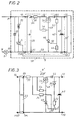
- the supply unit 9 comprises a rectification 23 by diode bridge transforming the alternating voltage present at inputs 10 and 11A in a full-wave rectified voltage delivered in colon 24 and 25.
- a reservoir capacitor 40 is connected between outputs 12 and 13 of the power supply unit 9.
- the supply unit 9 comprises in series a current limiting resistor 30 and a member switch 34, in this case a semiconductor field effect transistor metal oxide (FETMOS) with a grid 48.
- a bridge of resistors 42 and 44 connected in parallel with the capacitor 40 forms a branch 45 between the line 28 and a line 50 connecting point 25 and outlet 13.
- a blocking means 46 in in this case a thyristor, is connected between the gate 48 of the transistor 34 and the line 50.
- the trigger 52 of the locking means 46 is connected to the branch 45 between the resistors 42 and 44.
- a resistor 54 is connected between drain and gate 48 of the transistor 34.
- a diode 55 is connected to line 28, between the source of the transistor 34 and branch 45.
- the apparatus 1A has two operating modes, one said to the other one says stop.
- stop mode the power triac 5 is non-conducting and the lamp 2 is simply traversed by the current passing through the supply unit 9, in a state called extinction.
- the control device 7 controls the triac 5 by phase closure. During the first part of each alternation of the alternating voltage where the power triac 5 remains non-conducting, the lamp 2 is simply traversed by the current passing through the supply unit 9. During the rest of the alternating alternating voltage where the power triac 5 is turned on, the lamp 2 is supplied in a state called ignition.
- the unit supply 9 has two operating phases, a first phase said charge and a second phase called waiting.
- the capacitor 40 When the device 1A is energized, the capacitor 40 is not not loaded.
- the transistor 34 is non-conducting but a leakage current flows between its drain and its source from the moment of energization.
- the transistor 34 tends to switch to the on state when the voltage between points 24 and 25 increases.
- the voltage between the points 24 and 25 At the start of alternating alternating voltage, the voltage between the points 24 and 25 is insufficient for transistor 34 to go on especially taking into account the voltage drop across resistor 30.
- the conduction of transistor 34 thus intervenes a certain time after the zero of the tension, at the moment when the tension between points 24 and 25 is sufficient for the voltage present between gate 48 and source of transistor 34 allows its conduction.
- the so-called charging phase of the capacitor 40 begins, the current of the capacitor passing through the main source drain channel of the series transistor 34.
- Resistor 42 and resistor 44 form a divider bridge of the voltage present across the capacitor 40.
- the capacitor 40 is considered to be charged when the voltage at its terminals reaches a ceiling level representative of the load desired to dispose of enough energy to power the control device 7 at least during the so-called waiting phase, namely during a time interval at the end from which the voltage across the capacitor 40 drops to a value corresponding to the minimum supply voltage value of the device control electronics 7.
- the voltage present across resistor 44 of the divider bridge voltage reaches a fraction of said ceiling level sufficient to initiate the thyristor 46.
- the transition to the on state of the thyristor 46 causes the voltage between gate 48 and the source of transistor 34 so that the latter become non-passing.
- the charging of the capacitor 40 is then interrupted.
- the so-called charging phase is ended and a so-called waiting phase begins.
- the reservoir capacitor 40 begins to discharge to power the device control electronics 7.
- the thyristor 46 remains in the on state until the next zero crossing of the alternating current marking the end of alternating current of alternating current.
- the electronic control device 7 controls the priming of the triac 5 during the so-called waiting phase.
- phase Wait If the lamp 2 has a capacitive type behavior, the zero crossing of current occurs before the voltage crosses zero, during the so-called phase Wait.
- the variant of the power supply unit 9 'illustrated in FIG. 3 differs from the exemplary embodiment illustrated in FIG. 2 by the priming means of the thyristor 46.
- the voltage divider bridge of line 45 of power supply unit 9 is replaced in the supply unit 9 'by a line 45' comprising a zener diode 70 connected to the source of transistor 34 on line 28 'upstream of capacitor 40 and to a series resistor 72 connected on the one hand to the trigger of the thyristor 46 and on the other hand to a resistor 74 connected to the line 28 'upstream of the transistor 34.
- the thyristor 46 of the power supply unit 9 starts when the voltage across capacitor 40 has reached ceiling level, voltage across of the zener diode 70 then becoming sufficient for the latter to be passing and that the current flowing in line 45 'allows, the priming of the thyristor 46, but here, depending on the value of the resistor 74, the thyristor 46 can also be started when the tension between points 24 and 25 reaches a certain threshold corresponding to a determined value of the absolute value instantaneous of the alternating voltage applied to the input of the power supply unit 9 '. We thus extend the so-called waiting phase during the whole alternation part where the voltage between points 24 and 25 exceeds said certain threshold. We thus create an additional means of protection against overheating.
- the variant of the 9 "power unit illustrated in FIG. 4 differs from the embodiment illustrated in Figure 2 by the load control means of the reservoir capacitor 40, in particular by the control means of the switching of the series transistor 34.
- a 45 "branch connected in parallel with the reservoir capacitor 40 has a zener diode 80 and a resistor 82.
- a bipolar transistor 84 forming here the blocking means of transistor 34 is connected by its collector to a resistor 86 connected to the gate 48 of the transistor 34 and by its emitter to the line 50 ".
- the base of transistor 84 is connected to branch 45" between the diode zener 80 and resistor 82.
- a resistor 90 and a MOSFET transistor 92 forming means for blocking transistor 34 are connected to a line 88 connecting line 28 "and line 50" upstream of transistor 34.
- a resistor 94 is connected on the one hand to the junction of the resistor 90 to the drain of the transistor 92 and on the other hand at the junction of resistor 86 at the collector of transistor 84.
- a resistor 96 and resistor 98 form a dividing bridge 100 between the lines 28 "and 50" upstream from the line 88.
- the gate 102 of the transistor 92 is connected to the divider 100 between resistor 96 and resistor 98.
- the switching command in the non-state passing from the series transistor 34 when the capacitor 40 is charged is effected by different from the switching command of transistor 34 of the unit 9 shown in Figure 2.
- so-called device shutdown mode 1A at power-up, the transistor 34 is passing at the start of alternating alternating voltage during a so-called charging phase, as soon as the voltage between points 24 and 25 is sufficient.
- the reservoir capacitor 40 is charged.
- Terminal voltage of the capacitor 40 is maintained at the ceiling level by stabilization of the pinch of the load current and balance of transistors 84 and 34 in a regime called linear intermediate between their blocked state (not passing) and their state passing.
- the so-called linear regime lasts short enough for the transistors 34 and 84 do not have time to heat up.
- the charge of the reservoir capacitor 40 and the so-called linear speed of the transistors 34 and 84 end when transistor 92 is on, i.e. when the voltage across the resistor 98 is sufficient to allow the conduction of transistor 92, the voltage across resistor 98 being proportional to the voltage across branch 100, which is a function of the absolute value of the instantaneous voltage present between inputs 10 and 11A.
- the transistor 92 is on when the voltage between points 24 and 25 is greater than a first threshold.
- the transistor 92 switches to the non-passing state.
- the capacitor 40 having supplied energy to the control device 7 while transistor 92 is on, the voltage across it is lower at the ceiling level.
- the transistor 84 is therefore non-conducting and the transistor 34 is passing.
- the so-called waiting phase ends and a so-called charging phase begins.
- the capacitor 40 is charged until the voltage across its terminals reaches the ceiling level.
- the so-called charging phase ends and a so-called phase waiting starts again.
- the transistor 34 remains on until the voltage across the terminals of the capacitor 40 reaches ceiling level.
- the so-called charging phase ends and a so-called waiting phase begins again.
- the transistor 92 remains on until the voltage between the points 24 and 25 again reaches the first threshold.
- a new so-called charging phase begins, followed by a new phase called waiting.
- the cycle of the so-called charging and waiting phases continues the same principle during subsequent alternations.
- transistor 34 cannot be on to allow charging of capacitor 40 only when the voltage across the latter is lower at the ceiling level, when the voltage between points 24 and 25 is less than first threshold. There is a so-called charging phase when the series transistor 34 is passing.
- cut-off means 5 Three types of control of the cut-off means 5 can arise. if the cut-off means 5 can be ordered to close as at the opening.
- the cut-off means 5 is controlled in the state going into "phase opening" mode. Under the action of the electronic device 7, the cut-off means 5 is switched to the on state from the zero crossing of the alternating voltage and remains on for a delay predetermined programmed in the control device 7, up to an instant of the second half of alternation where the tension between points 24 and 25 reaches a second threshold greater than the first threshold.
- the 9 "power supply unit is supplied at the end of the voltage alternation alternative.
- the transistor 34 is on as long as the voltage across the terminals of the capacitor 40 is below ceiling level and as long as the voltage between points 24 and 25 is less than the first threshold.
- the cut-off means 5 is controlled in the state going into "phase closure" mode. Under the action of the electronic device 7, the cut-off means 5 is only switched to the on state after a predetermined delay programmed in the control device 7 subsequent to the zero current crossing of the alternating current, at a time in the first half alternation where the voltage between points 24 and 25 reaches the second threshold.
- the 9 "power supply unit is supplied at the start of alternating voltage alternative.
- the transistor 34 is on as long as the voltage across the terminals of the capacitor 40 is below ceiling level and as long as the voltage between points 24 and 25 is less than the first threshold.
- the cut-off means 5 is on for one middle part of each half-wave of the alternating voltage.
- the cut-off means 5 is only switched to the on state only after a predetermined delay subsequent to the zero crossing of the alternating voltage at a time when the voltage between points 24 and 25 is equal at the second threshold. It remains in the on state for a determined time memorized in the control device 7 such that its switching to the non-conducting state takes place before the AC voltage goes to zero marking the end of the alternation in progress, at a time when the tension between points 24 and 25 is equal to the second threshold.
- the 9 "supply unit is supplied at the start and end of the half-cycle.
- transistor 34 is on at the start of alternation (when the voltage between the points 24 and 25 is sufficient) and at the end of the alternation as long as the voltage across the capacitor 40 is below ceiling level and as long as the voltage between points 24 and 25 is less than the first threshold.
- the deadlines seen above and the first and second thresholds must be chosen so that the power unit can operate in connecting its inputs to an alternating voltage source of 110 Volts or 220 Volts.
- Each embodiment of the power supply unit has been described installed according to a two-wire assembly. We will observe that they are each compatible with a three-wire assembly (point 11A of units 9, 9 'and 9 "replaced by a point 11B directly connected to neutral), the operation of the power supply unit then being independent of the on or off mode of the cut-off means 5, all of each alternation being available at the input terminals.
- the power transistor 34 with field is replaced by a gate bipolar power transistor isolated (IGBT).
Landscapes
- Engineering & Computer Science (AREA)
- Power Engineering (AREA)
- Stand-By Power Supply Arrangements (AREA)
- Vehicle Body Suspensions (AREA)
- Filling Or Discharging Of Gas Storage Vessels (AREA)
- Electronic Switches (AREA)
- Control Of Electrical Variables (AREA)
Applications Claiming Priority (2)
| Application Number | Priority Date | Filing Date | Title |
|---|---|---|---|
| FR0016689A FR2818459B1 (fr) | 2000-12-20 | 2000-12-20 | Appareil muni d'un dispositif electronique de commande d'une charge et d'une unite d'alimentation de ce dispositif |
| FR0016689 | 2000-12-20 |
Publications (2)
| Publication Number | Publication Date |
|---|---|
| EP1220436A2 true EP1220436A2 (de) | 2002-07-03 |
| EP1220436A3 EP1220436A3 (de) | 2005-01-05 |
Family
ID=8857942
Family Applications (1)
| Application Number | Title | Priority Date | Filing Date |
|---|---|---|---|
| EP01403315A Withdrawn EP1220436A3 (de) | 2000-12-20 | 2001-12-20 | Anordnung mit einer elektronischen Laststeuerungsvorrichtung und einer Stromversorgungseinheit für solche Vorrichtung |
Country Status (2)
| Country | Link |
|---|---|
| EP (1) | EP1220436A3 (de) |
| FR (1) | FR2818459B1 (de) |
Cited By (2)
| Publication number | Priority date | Publication date | Assignee | Title |
|---|---|---|---|---|
| GB2467590A (en) * | 2009-02-09 | 2010-08-11 | Novar Ed & S Ltd | Power supply and control apparatus for an environmental conditioning system |
| EP3110006A1 (de) * | 2015-06-23 | 2016-12-28 | Climas Technology Co., Ltd. | Steuerungssystem für einen drahtlosen leistungsschalter ohne neutralleiter |
Family Cites Families (3)
| Publication number | Priority date | Publication date | Assignee | Title |
|---|---|---|---|---|
| DE3041840C2 (de) * | 1980-11-06 | 1989-01-12 | Honeywell Gmbh, 6050 Offenbach | Zweidraht-Speiseschaltung |
| GB2180938B (en) * | 1985-09-24 | 1990-02-28 | Square D Co | Low leakage, a c proximity switch circuit |
| AU1755695A (en) * | 1994-02-28 | 1995-09-11 | Linak A/S | A system for off-mains switching of current consuming devices such as actuators |
-
2000
- 2000-12-20 FR FR0016689A patent/FR2818459B1/fr not_active Expired - Fee Related
-
2001
- 2001-12-20 EP EP01403315A patent/EP1220436A3/de not_active Withdrawn
Cited By (4)
| Publication number | Priority date | Publication date | Assignee | Title |
|---|---|---|---|---|
| GB2467590A (en) * | 2009-02-09 | 2010-08-11 | Novar Ed & S Ltd | Power supply and control apparatus for an environmental conditioning system |
| GB2467590B (en) * | 2009-02-09 | 2013-02-06 | Novar Ed & S Ltd | An environmental conditioning system |
| EP3110006A1 (de) * | 2015-06-23 | 2016-12-28 | Climas Technology Co., Ltd. | Steuerungssystem für einen drahtlosen leistungsschalter ohne neutralleiter |
| US10008351B2 (en) | 2015-06-23 | 2018-06-26 | Climax Technology Co., Ltd. | Control system for a wireless power switch without a neutral wire |
Also Published As
| Publication number | Publication date |
|---|---|
| EP1220436A3 (de) | 2005-01-05 |
| FR2818459B1 (fr) | 2004-03-12 |
| FR2818459A1 (fr) | 2002-06-21 |
Similar Documents
| Publication | Publication Date | Title |
|---|---|---|
| EP1119094B1 (de) | Verfahren und Vorrichtung zur Elektrizitätsversorgung einer Last die aus einem Dimmer mit zumindest einem kontrollierten Schalter besteht | |
| EP3435396B1 (de) | Steuerbares gerät zur unterbrechung eines elektrischen stroms, und elektrische anlage, die ein solches gerät umfasst | |
| EP1271738B2 (de) | Elektronische Auslösevorrichtung mit einem Kondensator für die Stromversorgung einer Auslösespule | |
| EP0806781A1 (de) | Schaltung zur geschützten Versorgung einer elektrischen Last | |
| EP0623991B1 (de) | Leistungs oder Geschwindigkeitssteuerung einer Last | |
| FR2547133A1 (fr) | Circuit destine a prevenir une dissipation excessive d'energie dans les dispositifs commutateurs de puissance | |
| EP2073367B1 (de) | Wechselspannungsgenerator ausgestattet mit einem Strombegrenzer | |
| FR2908553A1 (fr) | Circuit de lancement d'alimentation pour une unite de declenchement et interrupteur de circuit comprenant celui-ci | |
| EP1220436A2 (de) | Anordnung mit einer elektronischen Laststeuerungsvorrichtung und einer Stromversorgungseinheit für solche Vorrichtung | |
| FR2525386A1 (fr) | Dispositif de commutation de charges electriques du type resistif et selfique alimentees en courant alternatif | |
| EP0235050A1 (de) | Steuerungsvorrichtung für elektrische Geräte | |
| FR2653593A1 (fr) | Telerupteur a dispositif de limitation de courant ref. 1736. | |
| FR3099289A1 (fr) | Contacteur et procédé de commande d’un contacteur | |
| EP1227590B1 (de) | Verfahren und Vorrichtung zum Aufbereiten von einer zum Betrieb eines elektronischen Schalters nötigen Versorgungsspannung | |
| EP0614259B1 (de) | Differenzstromschalter zum Schutz gegen Fehlerströme und Überspannungen | |
| FR2581239A1 (fr) | Circuit d'interruption a semiconducteur | |
| FR2702894A1 (fr) | Circuit d'un interrupteur bifilaire. | |
| EP3041102B1 (de) | Kapazitive einspeisevorrichtung zur steuerung eines elektrischen abschaltungsgeräts | |
| EP1198047A1 (de) | Begrenzer für elektrische Leistung in einer Anlage | |
| FR2561046A1 (fr) | Dispositif de coupe-circuit pour moteurs a courant alternatif commandes par thyristors | |
| FR2770942A1 (fr) | Procede et dispositif de variation de puissance de tension et courant nominatif defini sur une alimentation alternative | |
| FR2599183A1 (fr) | Procede et dispositif de commande d'un electro-aimant dont l'excitation par un courant periodique monoarche, provoque l'actionnement d'une piece mobile | |
| FR2703858A1 (fr) | Dispositif de protection contre les surintensités pour un régulateur. | |
| FR2655490A3 (fr) | Appareil de commande a circuit d'alimentation en basse tension, en particulier thermostat. | |
| FR2757702A1 (fr) | Appareil electrique comportant une entree de commande |
Legal Events
| Date | Code | Title | Description |
|---|---|---|---|
| PUAI | Public reference made under article 153(3) epc to a published international application that has entered the european phase |
Free format text: ORIGINAL CODE: 0009012 |
|
| AK | Designated contracting states |
Kind code of ref document: A2 Designated state(s): AT BE CH CY DE DK ES FI FR GB GR IE IT LI LU MC NL PT SE TR |
|
| AX | Request for extension of the european patent |
Free format text: AL;LT;LV;MK;RO;SI |
|
| PUAL | Search report despatched |
Free format text: ORIGINAL CODE: 0009013 |
|
| AK | Designated contracting states |
Kind code of ref document: A3 Designated state(s): AT BE CH CY DE DK ES FI FR GB GR IE IT LI LU MC NL PT SE TR |
|
| AX | Request for extension of the european patent |
Extension state: AL LT LV MK RO SI |
|
| RIC1 | Information provided on ipc code assigned before grant |
Ipc: 7H 02M 5/293 B Ipc: 7H 02M 5/257 A |
|
| AKX | Designation fees paid | ||
| REG | Reference to a national code |
Ref country code: DE Ref legal event code: 8566 |
|
| STAA | Information on the status of an ep patent application or granted ep patent |
Free format text: STATUS: THE APPLICATION IS DEEMED TO BE WITHDRAWN |
|
| 18D | Application deemed to be withdrawn |
Effective date: 20050706 |