EP1220460A2 - Procedé et circuit de réduction de pertes dans un émetteur radio - Google Patents
Procedé et circuit de réduction de pertes dans un émetteur radio Download PDFInfo
- Publication number
- EP1220460A2 EP1220460A2 EP01660249A EP01660249A EP1220460A2 EP 1220460 A2 EP1220460 A2 EP 1220460A2 EP 01660249 A EP01660249 A EP 01660249A EP 01660249 A EP01660249 A EP 01660249A EP 1220460 A2 EP1220460 A2 EP 1220460A2
- Authority
- EP
- European Patent Office
- Prior art keywords
- filter
- receiver
- antenna
- band
- transmitting end
- Prior art date
- Legal status (The legal status is an assumption and is not a legal conclusion. Google has not performed a legal analysis and makes no representation as to the accuracy of the status listed.)
- Granted
Links
Images


Classifications
-
- H—ELECTRICITY
- H04—ELECTRIC COMMUNICATION TECHNIQUE
- H04B—TRANSMISSION
- H04B1/00—Details of transmission systems, not covered by a single one of groups H04B3/00 - H04B13/00; Details of transmission systems not characterised by the medium used for transmission
- H04B1/02—Transmitters
- H04B1/04—Circuits
- H04B1/0475—Circuits with means for limiting noise, interference or distortion
-
- H—ELECTRICITY
- H03—ELECTRONIC CIRCUITRY
- H03F—AMPLIFIERS
- H03F1/00—Details of amplifiers with only discharge tubes, only semiconductor devices or only unspecified devices as amplifying elements
- H03F1/02—Modifications of amplifiers to raise the efficiency, e.g. gliding Class A stages, use of an auxiliary oscillation
-
- H—ELECTRICITY
- H03—ELECTRONIC CIRCUITRY
- H03F—AMPLIFIERS
- H03F3/00—Amplifiers with only discharge tubes or only semiconductor devices as amplifying elements
- H03F3/20—Power amplifiers, e.g. Class B amplifiers, Class C amplifiers
- H03F3/24—Power amplifiers, e.g. Class B amplifiers, Class C amplifiers of transmitter output stages
-
- H—ELECTRICITY
- H04—ELECTRIC COMMUNICATION TECHNIQUE
- H04B—TRANSMISSION
- H04B1/00—Details of transmission systems, not covered by a single one of groups H04B3/00 - H04B13/00; Details of transmission systems not characterised by the medium used for transmission
- H04B1/38—Transceivers, i.e. devices in which transmitter and receiver form a structural unit and in which at least one part is used for functions of transmitting and receiving
- H04B1/40—Circuits
- H04B1/403—Circuits using the same oscillator for generating both the transmitter frequency and the receiver local oscillator frequency
- H04B1/406—Circuits using the same oscillator for generating both the transmitter frequency and the receiver local oscillator frequency with more than one transmission mode, e.g. analog and digital modes
-
- H—ELECTRICITY
- H04—ELECTRIC COMMUNICATION TECHNIQUE
- H04B—TRANSMISSION
- H04B1/00—Details of transmission systems, not covered by a single one of groups H04B3/00 - H04B13/00; Details of transmission systems not characterised by the medium used for transmission
- H04B1/02—Transmitters
- H04B1/04—Circuits
- H04B2001/0408—Circuits with power amplifiers
- H04B2001/045—Circuits with power amplifiers with means for improving efficiency
Definitions
- the invention relates to an arrangement for reducing losses at the transmitting end of a radio apparatus, especially one that operates in multiple systems.
- the invention also relates to a method for reducing losses at the transmitting end of a radio apparatus operating in multiple systems.
- Radio apparatuses generally need filters in order to attenuate undesired frequency components and noise.
- One such point is after the power amplifier of a transmitter, before the antenna.
- a transmitting-end filter placed there prevents frequency components outside the transmitting band of the signal to be transferred from radiating into the environment and, furthermore, in the case of a bidirectional apparatus in which transmitting and reception take place in different bands, the transmitting is prevented from interfering with the reception.
- a filter on the transmission path also causes some attenuation in the signal to be transferred the spectrum of which is in the pass band of the filter. All attenuation prior to the transmitting antenna is especially harmful since increased losses between the power amplifier and antenna will result in increased current consumption in the power amplifier as well as potential heating problems.
- the transmitting-end filter may be a relatively simple low-pass filter where the pass-band attenuation can be brought relatively low, say, down to 0.5dB.
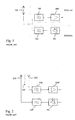
- Fig. 1 depicts such a case.
- a radio-frequency power amplifier PA and transmitting-end filter 120 belonging to a transmitter in one system and a receiving-end filter 130 and low-noise amplifier LNA belonging to a receiver in a second system.
- the systems share an antenna 110.
- the second system may be e.g. the GPS (Global Positioning System) the reception frequency of which is 1575.42 MHz.
- the GPS reception will be susceptible to interference caused by GSM transmissions.
- the GSM transmitting end requires something more than a low-pass filter or a band-pass filter the stop-band attenuation of which increases slowly when moving downward from the operating band.
- the filter must be a band-pass filter the attenuation of which increases sharply below the bass band.
- the GPS reception frequency and GSM transmitting band are only 125 MHz apart, and GPS reception has got strict requirements regarding interference.
- the antenna filter 120 in the first system is a "true" band-pass filter described above.
- the pass-band attenuation of the band-pass filter required is inevitably higher than that of the low-pass-type filter replaced by it.
- the increase in the attenuation is typically in the order of 2dB.
- An increase of 0.1dB in the pass-band attenuation of a transmitting-end filter causes in practice an increase of at least two percent in the current consumption of the power amplifier.
- Interference-free GPS reception thus means an increase of several tens of percent in the current consumption of the GSM transmitter. This, in turn, means that the thermal design of the apparatus becomes more demanding and, on the other hand, the charging interval of the battery of the phone becomes shorter.
- a mobile station is provided with e.g. Bluetooth or WLAN (Wireless Local Area Network) technology in addition to its basic technology and especially if transmission and reception in the same system occasionally take place simultaneously in the device.
- a situation may arise e.g. in a phone built to support the GPRS (General Packet Radio System) class that requires simultaneous transmitting and reception.
- GPRS General Packet Radio System
- a filter is needed after the power amplifier where the attenuation of the filter on the reception band is e.g. 50dB higher than what is needed in normal speech mode.
- the filter must be designed in accordance with the worst case which means that most of the time the filter structure is unnecessarily heavy and causes unnecessary pass-band attenuation.
- a separate antenna for the receiver suffering from interference from the transmitter and by arranging for sufficient isolation between the transmitting and receiving antennas.
- Such a solution is shown in Fig. 2.
- a radio-frequency power amplifier PA low-pass-type receiving-end filter LPF
- a transmitting antenna 210 as well as a separate receiving antenna 220 connected to a receiving-end antenna filter 230 which, in turn, is connected to a low-noise amplifier LNA.
- LNA low-noise amplifier
- FIG. 2 further shows a broken line 205 between the antennas, referring to an arrangement which provides for electromagnetic isolation between the transmitting and receiving antennas.
- a disadvantage of this solution is that it requires additional hardware and space and furthermore increases the production costs. Moreover, the antenna isolation which is achieved does not necessarily alone suffice to attenuate the interferences.
- An object of the invention is to reduce the said disadvantages associated with the prior art.
- the structure according to the invention is characterized by that which is specified in the independent claim 1.
- the method according to the invention is characterized by that which is specified in the independent claim 13.
- Advantageous embodiments of the invention are specified in the other claims.
- the interfering transmitter is provided with two antenna filters one of which is of the low-pass type, for example, and the other a band-pass filter.
- the filter with a higher stop-band attenuation is used only when the receiver susceptible to interference is in receive state.
- the filter with a lower stop-band attenuation and, hence, a lower pass-band attenuation is used as a transmitting-end filter.
- the selection between the different filters is realized using MEMS (Microelectro-Mechanical System) type switches.
- An advantage of the invention is that it minimizes the mean current consumption of a radio-frequency power amplifier in a radio apparatus operating in multiple systems. This is because the transmitting-end filter required by the receiver susceptible to interference is used only for a relatively short period of time and, on the other hand, because the MEMS switches, which are placed in the signal transmission path in order to realize switching between transmitting-end filters, have got very low transfer resistances and require very little control power.
- Another advantage of the invention is that the switch arrangement according to the invention does not cause spurious radiation, which may be caused by semiconductor switches because of their nonlinearity.
- a further advantage of the invention is that the space required by and the production costs of the arrangement according to the invention are relatively small.
- Fig. 3 shows in the form of block diagram an example of a structure according to the invention. It shows, like Fig. 1, a radio-frequency power amplifier PA belonging to a transmitter in a first system, a receiving-end filter 330 and low-noise amplifier LNA belonging to a receiver, and a common antenna 310. The receiver may belong to another or the same system as the transmitter. Replacing the transmitting-end filter shown in Fig. 1, there are now two parallel antenna filters; a low-pass-type filter LPF and a band-pass filter BPF.
- a "transmitting-end filter” means a filter in the signal path between the power amplifier and antenna
- “antenna filter” means a filter which can be connected as a transmitting-end filter or part of a transmitting-end filter.
- Fig. 3 shows switch units MEMSa and MEMSb which both are simple selectors; the former has got one input and two outputs, and the latter has got two inputs and one output.
- the output of the power amplifier PA is connected to the input of selector MEMSa.
- This selector includes two make switches SW31 and SW32. The input of the selector leads to the first output via switch SW31 and to the second output via switch SW32.
- the first output is connected to the input of the low-pass-type filter and the second output to the input of the band-pass filter.
- the output of the low-pass-type filter is connected to the first input of the second selector MEMSb and the output of the band-pass filter to the second input of the second selector.
- the second selector includes two make switches SW33 and SW34.
- the first input of the selector leads to the common output via switch SW33 and the second input via switch SW34.
- the output of the selector MEMSb is connected to the antenna. The selectors are controlled so that either the switches SW31 and SW33 are closed and switches SW32 and SW34 open or switches SW32 and SW34 are closed and switches SW31 and SW33 are open.
- the band-pass filter is used only when the said receiver is in receive state.
- the switch control signal C3 contains status information for the receiver and it comes from the control part of the whole radio apparatus.
- the receiver in Fig. 3 belongs to the second system, the first system naturally has got a receiver of its own, which is not shown in the figure.
- the receiver is connected to the common antenna through a conventional antenna switch.
- MEMS switches are very small electromechanical elements designed for the switching of high-frequency signals.
- the area of an individual switch is, depending on its structure, e.g. 1/3 mm 2 .
- the switches are voltage-controlled: When a high enough voltage is brought between the control electrodes, one of which is in the spring element, an electrostatic force draws the contacts of the switch together. The holding power is insignificant. Thanks to mechanical contacts, the transfer resistance of the switch is small; the attenuation caused by a MEMS switch on a high-frequency signal is typically only 0.1dB to 0.2dB. Insulation characteristic, i.e. isolation when the switch open, is considerably higher than in diode switches.
- Fig. 4 shows in the form of block diagram a second example of a structure according to the invention.
- the difference from the structure of Fig. 3 is that there are now three parallel filters, a low-pass-type filter LPF, a first band-pass filter BPF1, and a second band-pass filter BPF2.
- the selectors realized using MEMS switches are larger.
- the filter input side selector MEMSc has one input and three outputs, and the filter output side selector MEMSd has three inputs and one output.
- the switch control signal C4 which in this case must comprise at least two bits, determines which of the said three filters is connected between the power amplifier PA and antenna 410. In Fig. 4 it is the low-pass-type filter LPF.
- the number of filters is due to the fact that the radio apparatus in question operates in three systems.
- the pass band of the band-pass filter BPF1 covers the transmitting band of the GSM1800 system
- the pass band of the band-pass filter BPF2 covers the transmitting band of the GSM1900 system.
- the low-pass-type filter LPF is used always when the third system GPS in the example of Fig. 4 is not in receive state or when neither of the bands 1800 and 1900 requires simultaneous transmitting and reception.
- the control signal C4 comes from a control unit CU4, to which is brought the receiver status information STR, status information STT1 of the GSM1800 transmitter, and the status information STT2 of the GSM1900 transmitter from the control part of the whole radio apparatus.
- Fig. 5 shows a third possible implementation of the invention. It shows a radio-frequency power amplifier PA, a low-pass-type filter LPF, and a band-pass filter BPF belonging to a transmitter in a first system, and a receiving-end filter 530 and low-noise amplifier LNA belonging to a receiver, and a common antenna 510.
- the difference from the preceding two structures is that the filters may now be connected in series.
- the low-pass-type filter LPF is now connected in a fixed manner to the output of the power amplifier PA, and the band-pass filter BPF may be either shunted or connected in series with the low-pass-type filter.
- selector MEMSe which comprises three make switches SW51, SW52 and SW53.
- switch SW51 is connected to the output of the low-pass-type filter and the other to the feed conductor of the antenna.
- One pole of switch SW52 is connected to the output of the low-pass-type filter and the other to the input of the band-pass filter.
- One pole of switch SW53 is connected to the output of the band-pass filter and the other to the antenna feed conductor.
- the selector is controlled so that either the switch SW51 is closed and switches SW52 and SW53 are open or switch SW51 is open and switches SW52 and SW53 are closed.
- the band-pass filter is shunted and only the low-pass-type filter is connected between the power amplifier and antenna.
- the band-pass filter is connected in series with the low-pass-type filter between the power amplifier and antenna.
- the band-pass filter is used only when the said receiver is in receive state in which a higher stop-band attenuation is needed.
- the switch control signal C5 comes from a control unit CU5 to which is brought receiver status information STR and transmitter status information STT from the control part of the radio apparatus.
- the low-pass-type filter LPF may also be located between the selector MEMSe and antenna.
- Fig. 5 The structure shown in Fig. 5 is possible because of the good isolation in the MEMS switches. To further enhance the isolation it is possible to replace switch SW51 with two MEMS switches connected in series.
- Figs. 3 to 5 show switches only for one conductor in the signal path.
- the other conductor is assumed to be the ground conductor, which is not shown.
- the output of the power amplifier may also be balanced, in which case the selectors according to the invention comprise switches for both conductors in the antenna feed line. In that case there is another, separate switch in parallel with every switch shown in Figs. 3 to 5.
- Fig. 6 shows in the form of flow diagram an example of the method according to the invention for reducing transmitting-end losses.
- all transmitting-end antenna filters are disconnected from the rest of the circuit (step 601) in the circuit according to the invention.
- step 602 the state of the receiver susceptible to interference is observed. If the receiver is in inactive state, i.e. not in receive state, the low-pass-type filter is connected as transmitting-end filter in the interfering transmitter, and the other antenna filters are disconnected from the circuit, step 603. If the receiver is in receive state, it is checked in accordance with step 604 whether any relevant transmitter is in transmit state.
- step 605 If a first transmitter is in transmit state, the band-pass filter BPF1 which corresponds to its transmitting band is connected as transmitting-end filter, and the other antenna filters are disconnected from the circuit, step 605.
- the band-pass filter BPFn which corresponds to the transmitting band of the transmitter entering transmit state is connected as transmitting-end filter, and the other antenna filters are disconnected from the circuit, step 606.
- step 607 the power of the radio-frequency power amplifier is adjusted to a level where the radiation power of the antenna is in accordance with the specifications of the system in which the transmitter is operating. Following the said switching operations, and also in the case that no transmitter is in transmit state, the process returns to step 602, i.e. to monitor the state of the receiver susceptible to interference.
- Operation according to Fig. 6 means, among other things, that if the said receiver is not in receive state, the low-pass-type filter remains as transmitting-end filter even if the active transmitter was changed, in the case of multiple transmitters. So, a band-pass filter is selected, and in the case of multiple transmitters, the band-pass filter is changed, only if the said receiver is in receive state. This way, the losses in the power amplifier caused by the band-pass filters are minimized.
- the interfering transmitter is a GSM1800 transmitter and the interfered receiver is a GPS receiver
- the solution according to the invention brings a 30%-plus savings in the current consumption of the power amplifier when the positioning feature functions in the typical manner.
- thermal design becomes easier, which is desirable especially in mobile stations using GPRS.
- Fig. 7 shows a mobile station MS. It comprises near the antenna feed point a circuit 700 which includes the antenna filters and switches according to the invention.
- the invention does not limit the type of antenna used in the radio apparatus, nor the implementation of the antenna filters.
- the filters may be e.g. LC, resonator, or surface acoustic wave filters.
- the inventional idea may be applied in different ways within the limits defined by the independent claims.
Landscapes
- Engineering & Computer Science (AREA)
- Power Engineering (AREA)
- Computer Networks & Wireless Communication (AREA)
- Signal Processing (AREA)
- Transceivers (AREA)
- Transmitters (AREA)
Applications Claiming Priority (2)
| Application Number | Priority Date | Filing Date | Title |
|---|---|---|---|
| FI20002881A FI20002881A7 (fi) | 2000-12-29 | 2000-12-29 | Järjestely ja menetelmä radiolähettimen häviöiden vähentämiseksi |
| FI20002881 | 2000-12-29 |
Publications (3)
| Publication Number | Publication Date |
|---|---|
| EP1220460A2 true EP1220460A2 (fr) | 2002-07-03 |
| EP1220460A3 EP1220460A3 (fr) | 2004-01-14 |
| EP1220460B1 EP1220460B1 (fr) | 2007-09-05 |
Family
ID=8559837
Family Applications (1)
| Application Number | Title | Priority Date | Filing Date |
|---|---|---|---|
| EP01660249A Expired - Lifetime EP1220460B1 (fr) | 2000-12-29 | 2001-12-21 | Procedé et circuit de réduction de pertes dans un émetteur radio |
Country Status (4)
| Country | Link |
|---|---|
| US (1) | US7171235B2 (fr) |
| EP (1) | EP1220460B1 (fr) |
| DE (1) | DE60130315T2 (fr) |
| FI (1) | FI20002881A7 (fr) |
Cited By (22)
| Publication number | Priority date | Publication date | Assignee | Title |
|---|---|---|---|---|
| WO2004088865A1 (fr) * | 2003-04-02 | 2004-10-14 | Siemens Aktiengesellschaft | Ensemble circuit pour un terminal de communication a fonctionnement multimode |
| WO2006085139A2 (fr) | 2004-12-22 | 2006-08-17 | Nokia Corporation | Amelioration de l'interoperabilite entre des recepteurs et des emetteurs dans une station mobile |
| EP1843368A4 (fr) * | 2005-01-27 | 2009-06-03 | Mitsubishi Electric Corp | Circuit de commutation |
| WO2009086821A1 (fr) * | 2008-01-10 | 2009-07-16 | Epcos Ag | Circuit frontal |
| WO2010059872A3 (fr) * | 2008-11-19 | 2010-11-25 | Qualcomm Incorporated | Émetteur fm et récepteur non fm intégrés sur une puce unique |
| US8067840B2 (en) | 2006-06-20 | 2011-11-29 | Nxp B.V. | Power amplifier assembly |
| WO2012005787A1 (fr) * | 2010-07-08 | 2012-01-12 | Microsemi Corporation | Architecture améliorée pour coexistence de radios à plusieurs bandes |
| WO2012082220A1 (fr) * | 2010-10-13 | 2012-06-21 | Qualcomm Incorporated | Coexistence multi-radio |
| WO2013082924A1 (fr) * | 2011-12-07 | 2013-06-13 | 捷开通讯科技(上海)有限公司 | Système d'émission et de réception de communication sans fil |
| WO2013133928A1 (fr) * | 2012-03-07 | 2013-09-12 | Qualcomm Incorporated | Atténuation d'interférence multi-radio par l'intermédiaire de sélectivité de fréquence |
| US8594056B2 (en) | 2009-06-16 | 2013-11-26 | Qualcomm Incorporated | Method and apparatus for dynamic and dual antenna bluetooth (BT)/WLAN coexistence |
| CN103873084A (zh) * | 2009-02-04 | 2014-06-18 | 高通股份有限公司 | 响应于频谱信息的可调整的接收滤波器 |
| US8903314B2 (en) | 2009-10-29 | 2014-12-02 | Qualcomm Incorporated | Bluetooth introduction sequence that replaces frequencies unusable due to other wireless technology co-resident on a bluetooth-capable device |
| US9135197B2 (en) | 2009-07-29 | 2015-09-15 | Qualcomm Incorporated | Asynchronous interface for multi-radio coexistence manager |
| US9148889B2 (en) | 2009-06-01 | 2015-09-29 | Qualcomm Incorporated | Control of multiple radios using a database of interference-related information |
| US9161232B2 (en) | 2009-06-29 | 2015-10-13 | Qualcomm Incorporated | Decentralized coexistence manager for controlling operation of multiple radios |
| US9185718B2 (en) | 2009-06-29 | 2015-11-10 | Qualcomm Incorporated | Centralized coexistence manager for controlling operation of multiple radios |
| US9185719B2 (en) | 2009-08-18 | 2015-11-10 | Qualcomm Incorporated | Method and apparatus for mapping applications to radios in a wireless communication device |
| EP2991223A4 (fr) * | 2013-06-27 | 2016-05-25 | Huawei Device Co Ltd | Système de suppression d'harmoniques |
| US9433003B2 (en) | 2012-03-07 | 2016-08-30 | Qualcomm Incorporated | Multi-radio coexistence via timing controls for radios using the same radio access technology |
| EP3471278A1 (fr) * | 2012-02-23 | 2019-04-17 | QUALCOMM Incorporated | Dispositif sans fil ayant des filtres pour soutenir la coexistence dans des bandes de fréquences voisines |
| US20210336640A1 (en) * | 2020-04-24 | 2021-10-28 | Murata Manufacturing Co., Ltd. | Radio frequency circuit and communication device |
Families Citing this family (15)
| Publication number | Priority date | Publication date | Assignee | Title |
|---|---|---|---|---|
| JP2002204135A (ja) * | 2000-12-28 | 2002-07-19 | Matsushita Electric Ind Co Ltd | 高周波低域通過フィルタ |
| JP3937986B2 (ja) * | 2002-09-13 | 2007-06-27 | 株式会社村田製作所 | 送受信フィルタ装置および通信装置 |
| KR101058973B1 (ko) * | 2003-02-07 | 2011-08-23 | 에스티 에릭슨 에스에이 | 인터페이싱 방법 및 인터페이싱 회로 |
| KR100531879B1 (ko) * | 2003-07-09 | 2005-11-29 | 엘지전자 주식회사 | 휴대폰의 고주파 수신회로 |
| US7251499B2 (en) * | 2004-06-18 | 2007-07-31 | Nokia Corporation | Method and device for selecting between internal and external antennas |
| JP3981104B2 (ja) * | 2004-06-28 | 2007-09-26 | 株式会社東芝 | フィルタ回路及びこれを用いた無線通信装置 |
| US7554421B2 (en) * | 2006-05-16 | 2009-06-30 | Intel Corporation | Micro-electromechanical system (MEMS) trampoline switch/varactor |
| US7605675B2 (en) * | 2006-06-20 | 2009-10-20 | Intel Corporation | Electromechanical switch with partially rigidified electrode |
| KR100849972B1 (ko) * | 2007-01-25 | 2008-08-01 | 삼성전자주식회사 | Rf 필터, 이를 이용한 디지털 방송 수신 튜너 및 rf신호 처리 장치 |
| DE102007050606B3 (de) * | 2007-10-23 | 2009-04-23 | Epcos Ag | Schaltungsanordnung für eine Mobilfunkeinrichtung und Verfahren zum Betrieb |
| CN101789764A (zh) * | 2010-03-09 | 2010-07-28 | 广州市圣大电子有限公司 | 一种射频功率放大器 |
| JPWO2013021626A1 (ja) * | 2011-08-08 | 2015-03-05 | パナソニック株式会社 | フィルタモジュール |
| CN203522706U (zh) * | 2013-01-24 | 2014-04-02 | 芯迪半导体科技(上海)有限公司 | 多频段频率源 |
| CN109257082A (zh) * | 2017-07-14 | 2019-01-22 | 中兴通讯股份有限公司 | 一种天线切换处理方法、装置及系统 |
| WO2019021841A1 (fr) * | 2017-07-25 | 2019-01-31 | 株式会社村田製作所 | Circuit haute fréquence et dispositif de communication |
Family Cites Families (17)
| Publication number | Priority date | Publication date | Assignee | Title |
|---|---|---|---|---|
| US4422047A (en) * | 1981-11-23 | 1983-12-20 | E-Systems, Inc. | Solid state autotune power amplifier |
| US4980660A (en) * | 1986-10-06 | 1990-12-25 | Matsushita Electric Industrial Co., Ltd. | Antenna sharing apparatus for switchable transmit/receive filters |
| US5276914A (en) * | 1990-10-18 | 1994-01-04 | Sony Corporation | Dual-mode transceiver that switches out a large insertion loss filter during transmission |
| FI95327C (fi) | 1994-01-26 | 1996-01-10 | Lk Products Oy | Säädettävä suodatin |
| DE19514717C2 (de) | 1995-04-21 | 1998-07-16 | Siemens Ag | Schaltungsanordnung für eine Hochfrequenz-Verstärkerstufe insbesondere in einem Sendegerät |
| JP3100111B2 (ja) * | 1995-06-26 | 2000-10-16 | 株式会社エヌ・ティ・ティ・ドコモ | 移動無線機のマルチバンド高周波回路 |
| FI100286B (fi) * | 1996-04-01 | 1997-10-31 | Nokia Mobile Phones Ltd | Lähetin/vastaanotin RF-signaalin lähettämiseksi ja vastaanottamiseksi kahdella taajuusalueella |
| FI117841B (fi) * | 1996-07-18 | 2007-03-15 | Nokia Corp | Järjestely radiotaajuisen signaalin lähettämiseksi ja vastaanottamiseksi kahdella taajuusalueella |
| SE508506C2 (sv) * | 1997-02-25 | 1998-10-12 | Ericsson Telefon Ab L M | Anordning och förfarande vid telekommunikation |
| JPH10313226A (ja) * | 1997-05-12 | 1998-11-24 | Fujitsu Ltd | 送受分波器および送受分波器を搭載した無線通信装置 |
| US6212172B1 (en) * | 1998-05-08 | 2001-04-03 | Omnipoint Corporation | Filtering method to allow FDD and TDD operation in PCS transreceivers |
| DE19823049C2 (de) * | 1998-05-22 | 2000-09-21 | Ericsson Telefon Ab L M | Leistungsverstärker-Ausgangsschaltung zur Unterdrückung von Oberschwingungen für eine Mobilfunkeinheit mit Doppelbandbetrieb und Verfahren zum Betreiben derselben |
| GB2346049A (en) | 1999-01-19 | 2000-07-26 | Roke Manor Research | Duplex filtering |
| CN1132326C (zh) * | 1999-02-24 | 2003-12-24 | 三菱电机株式会社 | 无线终端装置 |
| US6442375B1 (en) * | 1999-07-14 | 2002-08-27 | Ericsson Inc. | Systems and methods for maintaining operation of a receiver co-located with a transmitter and susceptible to interference therefrom by desensitization of the receiver |
| US6628942B1 (en) * | 1999-10-06 | 2003-09-30 | Telefonaktiebolaget Lm Ericsson (Publ) | Method and apparatus for paging and responding to pages in a mobile radio communications system |
| US6662028B1 (en) * | 2000-05-22 | 2003-12-09 | Telefonaktiebolaget L.M. Ericsson | Multiple frequency inverted-F antennas having multiple switchable feed points and wireless communicators incorporating the same |
-
2000
- 2000-12-29 FI FI20002881A patent/FI20002881A7/fi unknown
-
2001
- 2001-12-20 US US10/027,089 patent/US7171235B2/en not_active Expired - Lifetime
- 2001-12-21 DE DE60130315T patent/DE60130315T2/de not_active Expired - Lifetime
- 2001-12-21 EP EP01660249A patent/EP1220460B1/fr not_active Expired - Lifetime
Cited By (34)
| Publication number | Priority date | Publication date | Assignee | Title |
|---|---|---|---|---|
| WO2004088865A1 (fr) * | 2003-04-02 | 2004-10-14 | Siemens Aktiengesellschaft | Ensemble circuit pour un terminal de communication a fonctionnement multimode |
| WO2006085139A2 (fr) | 2004-12-22 | 2006-08-17 | Nokia Corporation | Amelioration de l'interoperabilite entre des recepteurs et des emetteurs dans une station mobile |
| EP1829229A4 (fr) * | 2004-12-22 | 2015-05-13 | Nokia Corp | Amelioration de l'interoperabilite entre des recepteurs et des emetteurs dans une station mobile |
| US7675383B2 (en) | 2005-01-27 | 2010-03-09 | Mitsubishi Electric Corporation | Switch circuit |
| EP1843368A4 (fr) * | 2005-01-27 | 2009-06-03 | Mitsubishi Electric Corp | Circuit de commutation |
| US8067840B2 (en) | 2006-06-20 | 2011-11-29 | Nxp B.V. | Power amplifier assembly |
| WO2009086821A1 (fr) * | 2008-01-10 | 2009-07-16 | Epcos Ag | Circuit frontal |
| US8688045B2 (en) | 2008-11-19 | 2014-04-01 | Qualcomm Incorporated | FM transmitter and non-FM receiver integrated on single chip |
| WO2010059872A3 (fr) * | 2008-11-19 | 2010-11-25 | Qualcomm Incorporated | Émetteur fm et récepteur non fm intégrés sur une puce unique |
| CN102217204B (zh) * | 2008-11-19 | 2015-01-07 | 高通股份有限公司 | 集成于单芯片上的fm发射器和非fm接收器 |
| CN103873084B (zh) * | 2009-02-04 | 2016-06-22 | 高通股份有限公司 | 响应于频谱信息的可调整的接收滤波器 |
| CN103873084A (zh) * | 2009-02-04 | 2014-06-18 | 高通股份有限公司 | 响应于频谱信息的可调整的接收滤波器 |
| US9155103B2 (en) | 2009-06-01 | 2015-10-06 | Qualcomm Incorporated | Coexistence manager for controlling operation of multiple radios |
| US9148889B2 (en) | 2009-06-01 | 2015-09-29 | Qualcomm Incorporated | Control of multiple radios using a database of interference-related information |
| US8594056B2 (en) | 2009-06-16 | 2013-11-26 | Qualcomm Incorporated | Method and apparatus for dynamic and dual antenna bluetooth (BT)/WLAN coexistence |
| US9161232B2 (en) | 2009-06-29 | 2015-10-13 | Qualcomm Incorporated | Decentralized coexistence manager for controlling operation of multiple radios |
| US9185718B2 (en) | 2009-06-29 | 2015-11-10 | Qualcomm Incorporated | Centralized coexistence manager for controlling operation of multiple radios |
| US9135197B2 (en) | 2009-07-29 | 2015-09-15 | Qualcomm Incorporated | Asynchronous interface for multi-radio coexistence manager |
| US9185719B2 (en) | 2009-08-18 | 2015-11-10 | Qualcomm Incorporated | Method and apparatus for mapping applications to radios in a wireless communication device |
| US8903314B2 (en) | 2009-10-29 | 2014-12-02 | Qualcomm Incorporated | Bluetooth introduction sequence that replaces frequencies unusable due to other wireless technology co-resident on a bluetooth-capable device |
| US8670726B2 (en) | 2010-07-08 | 2014-03-11 | Microsemi Corporation | Architecture for coexistence of multiple band radios |
| WO2012005787A1 (fr) * | 2010-07-08 | 2012-01-12 | Microsemi Corporation | Architecture améliorée pour coexistence de radios à plusieurs bandes |
| WO2012082220A1 (fr) * | 2010-10-13 | 2012-06-21 | Qualcomm Incorporated | Coexistence multi-radio |
| US9130656B2 (en) | 2010-10-13 | 2015-09-08 | Qualcomm Incorporated | Multi-radio coexistence |
| WO2013082924A1 (fr) * | 2011-12-07 | 2013-06-13 | 捷开通讯科技(上海)有限公司 | Système d'émission et de réception de communication sans fil |
| EP3471278A1 (fr) * | 2012-02-23 | 2019-04-17 | QUALCOMM Incorporated | Dispositif sans fil ayant des filtres pour soutenir la coexistence dans des bandes de fréquences voisines |
| US9820158B2 (en) | 2012-03-07 | 2017-11-14 | Qualcomm Incorporated | Multi-radio interference mitigation via frequency selectivity |
| WO2013133928A1 (fr) * | 2012-03-07 | 2013-09-12 | Qualcomm Incorporated | Atténuation d'interférence multi-radio par l'intermédiaire de sélectivité de fréquence |
| US9433003B2 (en) | 2012-03-07 | 2016-08-30 | Qualcomm Incorporated | Multi-radio coexistence via timing controls for radios using the same radio access technology |
| EP2991223A4 (fr) * | 2013-06-27 | 2016-05-25 | Huawei Device Co Ltd | Système de suppression d'harmoniques |
| US9634772B2 (en) | 2013-06-27 | 2017-04-25 | Huawei Device Co., Ltd. | Harmonic suppression system |
| JP2016526834A (ja) * | 2013-06-27 | 2016-09-05 | ▲華▼▲為▼▲終▼端有限公司 | 高調波抑制システム |
| US20210336640A1 (en) * | 2020-04-24 | 2021-10-28 | Murata Manufacturing Co., Ltd. | Radio frequency circuit and communication device |
| US12395197B2 (en) * | 2020-04-24 | 2025-08-19 | Murata Manufacturing Co., Ltd. | Radio frequency circuit and communication device |
Also Published As
| Publication number | Publication date |
|---|---|
| US7171235B2 (en) | 2007-01-30 |
| US20020086650A1 (en) | 2002-07-04 |
| FI20002881L (fi) | 2002-06-30 |
| EP1220460B1 (fr) | 2007-09-05 |
| FI20002881A7 (fi) | 2002-06-30 |
| EP1220460A3 (fr) | 2004-01-14 |
| DE60130315T2 (de) | 2008-05-29 |
| FI20002881A0 (fi) | 2000-12-29 |
| DE60130315D1 (de) | 2007-10-18 |
Similar Documents
| Publication | Publication Date | Title |
|---|---|---|
| EP1220460B1 (fr) | Procedé et circuit de réduction de pertes dans un émetteur radio | |
| KR101256496B1 (ko) | 적응형 안테나 시스템 | |
| CN101877917B (zh) | 射频拉远单元 | |
| KR101803342B1 (ko) | 무선 네트워크에서 운용되는 다중대역 라디오 장치 및 방법 | |
| KR102140190B1 (ko) | 스위칭 유닛을 구비한 디바이스 및 그 애플리케이션 | |
| EP1649605B1 (fr) | Commutateur d'antenne a filtre adaptatif | |
| WO2014031369A1 (fr) | Filtrage coupe-bande accordable dans des applications à transmissions multiples | |
| EP2712476A1 (fr) | Circuiterie sans fil pour recevoir simultanément des transmissions radiofréquence dans différentes bandes de fréquence | |
| WO2009083647A1 (fr) | Appareil et procédé de commutation entre réception et émission | |
| EP1476961B1 (fr) | Systeme et procede fournissant des communications sans fil activees par gps | |
| EP1476948A2 (fr) | Appareil pour la communication a bandes multiples | |
| EP4254791A2 (fr) | Procédé et appareil de réglage d'antenne | |
| EP2351233B1 (fr) | Module frontal rf partagé pour application cellulaire | |
| US8600316B2 (en) | Wireless circuits with minimized port counts | |
| EP1723730B1 (fr) | Station de base et sa procedure de configuration | |
| EP3811520B1 (fr) | Unité radio pour opération multibande tdd non synchronisée | |
| CN118157688B (zh) | 通信装置及电子设备 | |
| US7162266B2 (en) | Multiple band handset architecture | |
| CN201191826Y (zh) | 一种多模移动通信终端及其射频接收电路 | |
| EP0923198A2 (fr) | Procedé de sélection de bande de fréquence pour dispositif de communication multibande , et dispositif de communication | |
| JP5332852B2 (ja) | 無線通信装置およびその通信方法 | |
| KR102211745B1 (ko) | 프론트 엔드 모듈 | |
| US20240223226A1 (en) | Radio frequency module with reduced intermodulation distortion | |
| CN100574140C (zh) | 采用射频开关阵列的td-scdma放大器 | |
| CN114665911A (zh) | 收发装置及信号处理方法 |
Legal Events
| Date | Code | Title | Description |
|---|---|---|---|
| PUAI | Public reference made under article 153(3) epc to a published international application that has entered the european phase |
Free format text: ORIGINAL CODE: 0009012 |
|
| AK | Designated contracting states |
Kind code of ref document: A2 Designated state(s): AT BE CH CY DE DK ES FI FR GB GR IE IT LI LU MC NL PT SE TR |
|
| AX | Request for extension of the european patent |
Free format text: AL;LT;LV;MK;RO;SI |
|
| PUAL | Search report despatched |
Free format text: ORIGINAL CODE: 0009013 |
|
| AK | Designated contracting states |
Kind code of ref document: A3 Designated state(s): AT BE CH CY DE DK ES FI FR GB GR IE IT LI LU MC NL PT SE TR |
|
| AX | Request for extension of the european patent |
Extension state: AL LT LV MK RO SI |
|
| RIC1 | Information provided on ipc code assigned before grant |
Ipc: 7H 04B 1/52 B Ipc: 7H 04B 1/40 A |
|
| AKX | Designation fees paid | ||
| 17P | Request for examination filed |
Effective date: 20040825 |
|
| RBV | Designated contracting states (corrected) |
Designated state(s): DE GB |
|
| 17Q | First examination report despatched |
Effective date: 20040923 |
|
| REG | Reference to a national code |
Ref country code: DE Ref legal event code: 8566 |
|
| 17Q | First examination report despatched |
Effective date: 20040923 |
|
| GRAP | Despatch of communication of intention to grant a patent |
Free format text: ORIGINAL CODE: EPIDOSNIGR1 |
|
| GRAS | Grant fee paid |
Free format text: ORIGINAL CODE: EPIDOSNIGR3 |
|
| GRAA | (expected) grant |
Free format text: ORIGINAL CODE: 0009210 |
|
| AK | Designated contracting states |
Kind code of ref document: B1 Designated state(s): DE GB |
|
| REG | Reference to a national code |
Ref country code: GB Ref legal event code: FG4D |
|
| REF | Corresponds to: |
Ref document number: 60130315 Country of ref document: DE Date of ref document: 20071018 Kind code of ref document: P |
|
| PLBE | No opposition filed within time limit |
Free format text: ORIGINAL CODE: 0009261 |
|
| STAA | Information on the status of an ep patent application or granted ep patent |
Free format text: STATUS: NO OPPOSITION FILED WITHIN TIME LIMIT |
|
| 26N | No opposition filed |
Effective date: 20080606 |
|
| REG | Reference to a national code |
Ref country code: GB Ref legal event code: 732E Free format text: REGISTERED BETWEEN 20150910 AND 20150916 |
|
| REG | Reference to a national code |
Ref country code: DE Ref legal event code: R082 Ref document number: 60130315 Country of ref document: DE Representative=s name: BECKER, KURIG, STRAUS, DE Ref country code: DE Ref legal event code: R081 Ref document number: 60130315 Country of ref document: DE Owner name: NOKIA TECHNOLOGIES OY, FI Free format text: FORMER OWNER: NOKIA CORP., 02610 ESPOO, FI |
|
| PGFP | Annual fee paid to national office [announced via postgrant information from national office to epo] |
Ref country code: DE Payment date: 20161213 Year of fee payment: 16 Ref country code: GB Payment date: 20161221 Year of fee payment: 16 |
|
| REG | Reference to a national code |
Ref country code: DE Ref legal event code: R119 Ref document number: 60130315 Country of ref document: DE |
|
| GBPC | Gb: european patent ceased through non-payment of renewal fee |
Effective date: 20171221 |
|
| PG25 | Lapsed in a contracting state [announced via postgrant information from national office to epo] |
Ref country code: DE Free format text: LAPSE BECAUSE OF NON-PAYMENT OF DUE FEES Effective date: 20180703 |
|
| PG25 | Lapsed in a contracting state [announced via postgrant information from national office to epo] |
Ref country code: GB Free format text: LAPSE BECAUSE OF NON-PAYMENT OF DUE FEES Effective date: 20171221 |