EP1220559A1 - Système de communication, unité de communication et méthode de localisation - Google Patents
Système de communication, unité de communication et méthode de localisation Download PDFInfo
- Publication number
- EP1220559A1 EP1220559A1 EP00403712A EP00403712A EP1220559A1 EP 1220559 A1 EP1220559 A1 EP 1220559A1 EP 00403712 A EP00403712 A EP 00403712A EP 00403712 A EP00403712 A EP 00403712A EP 1220559 A1 EP1220559 A1 EP 1220559A1
- Authority
- EP
- European Patent Office
- Prior art keywords
- location
- communication
- resource
- request signal
- location determination
- Prior art date
- Legal status (The legal status is an assumption and is not a legal conclusion. Google has not performed a legal analysis and makes no representation as to the accuracy of the status listed.)
- Withdrawn
Links
- 238000004891 communication Methods 0.000 title claims abstract description 124
- 238000000034 method Methods 0.000 title claims abstract description 71
- 230000000694 effects Effects 0.000 claims abstract description 29
- 230000005540 biological transmission Effects 0.000 claims abstract description 26
- 230000000116 mitigating effect Effects 0.000 claims abstract description 3
- 238000010295 mobile communication Methods 0.000 claims abstract 13
- 238000012544 monitoring process Methods 0.000 claims abstract 3
- 230000007480 spreading Effects 0.000 claims description 12
- 230000008569 process Effects 0.000 abstract description 19
- 230000011664 signaling Effects 0.000 abstract description 12
- 238000005259 measurement Methods 0.000 abstract description 4
- 230000001360 synchronised effect Effects 0.000 abstract description 3
- 230000008901 benefit Effects 0.000 description 6
- 238000013459 approach Methods 0.000 description 5
- 238000012545 processing Methods 0.000 description 5
- 230000001413 cellular effect Effects 0.000 description 4
- 238000010586 diagram Methods 0.000 description 2
- 230000004044 response Effects 0.000 description 2
- 230000008054 signal transmission Effects 0.000 description 2
- 239000002699 waste material Substances 0.000 description 2
- 239000004165 Methyl ester of fatty acids Substances 0.000 description 1
- 238000010420 art technique Methods 0.000 description 1
- 238000006243 chemical reaction Methods 0.000 description 1
- 230000001419 dependent effect Effects 0.000 description 1
- 238000001914 filtration Methods 0.000 description 1
- 230000006872 improvement Effects 0.000 description 1
- 238000002955 isolation Methods 0.000 description 1
- 230000007246 mechanism Effects 0.000 description 1
- 230000000737 periodic effect Effects 0.000 description 1
- 230000002441 reversible effect Effects 0.000 description 1
- 238000009738 saturating Methods 0.000 description 1
- 230000036962 time dependent Effects 0.000 description 1
- 238000012546 transfer Methods 0.000 description 1
Images


Classifications
-
- H—ELECTRICITY
- H04—ELECTRIC COMMUNICATION TECHNIQUE
- H04W—WIRELESS COMMUNICATION NETWORKS
- H04W64/00—Locating users or terminals or network equipment for network management purposes, e.g. mobility management
Definitions
- This invention relates to location procedures in a wireless communication system.
- the invention is applicable to, but not limited to, location procedures in the context of near-far interference problems in a UMTS TDD communication system.
- Wireless communication systems typically provide for radio telecommunication links to be arranged between a plurality of base transceiver stations (BTSs) and a plurality of subscriber units, often termed mobile stations (MSs).
- BTSs base transceiver stations
- MSs mobile stations
- Wireless communication systems are distinguished over fixed communication systems, such as the public switched telephone network (PSTN), principally in that mobile stations move between BTS (and/or different service providers) and, in doing so, encounter varying radio propagation environments.
- PSTN public switched telephone network
- duplex (two-way communication) paths are arranged.
- Such paths can be arranged in a frequency division duplex (FDD) configuration, whereby a frequency is dedicated for up-link communication and a second frequency is dedicated for down-link communication.
- FDD frequency division duplex
- TDD time division duplex
- each BTS has associated with it a particular geographical coverage area (or cell).
- the coverage area is defined by a particular range where the BTS can maintain acceptable communications with MSs operating within its serving cell. Often these cells combine to produce an extensive coverage area.
- the communication link from the BTS to a MS is referred to as the down-link (DL). Conversely, the communication link from a MS to the BTS is referred to as the up-link (UL).
- DL down-link
- UL up-link
- the near-far effect is mainly due to the fact that usually the networks are dimensioned to reduce the interference (both intra and inter-cell) as much as possible, for obvious capacity reasons. That means that reducing the inter-cell interference will automatically reduce the chance to listen (be listened) to (at other) BTSs
- FIG. 1 a representation of the near-far effect on wireless location in a current CDMA system 100, is shown.
- Three communication cells 104, 106, 108, are depicted, which are served by three BTSs: BTS-0 110, BTS-1 114 and BTS-2 112.
- the Target Mobile Station (MS) 102 whose location is desired is being served by BTS-0 110, whilst BTS-1 114 and BTS-2 112 will also be used for location purposes.
- the Target MS 102 is only power controlled by BTS-0 110.
- all MSs served by BTS-0 110 are co-ordinated such that the received signal strength of each arrives at BTS-0 110 with approximately equal power. The same is true for the MSs being served by BTS-1 114 and BTS-2 112, if they operate power control in cell-1 108 and cell-2 106 respectively.
- the signal from the Target MS 102 at BTS-1 114 and BTS-2 112 may experience severe multiple access interference from MSs being served by BTS-1 and BTS-2 since the Target MS is not power-controlled to those BTSs.
- the interference will consequently affect the ability of a conventional receiver to estimate correctly the information.
- the near-far effect in an uplink channel is a very severe constraint when the Target MS's transmission 116 has to be listened to by several (at least three) BTSs. This is particularly the case when operating a Remote Positioning Technique (RPT).
- RPT Remote Positioning Technique
- FIG. 1 (with reverse (arrows) signal transmissions) 116 from BTS to MS 102) also applies to the near-far effect in a down-link channel.
- the target MS 102 receives signals from different BTSs 110, 112, 114.
- BTS-0 110 performing the power control risks saturating the Target MS' receiver if the attenuation between BTS-0 110 and Target MS 102 is less important with respect to those corresponding to BTS-1 114 and BTS-2 112 signals (not performing power control).
- the signals received at Target MS 102 from BTS-1 114 and BTS-2 112 experience multiple access interference from downlink transmissions on BTS-0 110.
- the near far effect in a downlink channel is a very severe constraint when several BTSs (at least three) 110, 112, 114 have to be listened to by the target MS 102.
- the ideal situation would be to receive perfectly a Target MS signal at a BTS 110, 112, 114 on the up-link channel or to receive perfectly BTS signals at the Target MS 102 on the down-link channel.
- Three known techniques, to combat near-far effect, include:
- the existing techniques are either very dependent on the prevailing conditions, to allow SHO to be used, or they substantially disturb existing calls, by requiring creation of regular silence periods by shutting down BTS transmission.
- prior art techniques in resolving the near-far effect, are rarely acceptable in normal operation conditions.
- the present invention utilises the slotted structure in a TDD mode of a UMTS communication system, to combat the near-far interference (during a location determination process for example).
- Such a technique combats the near-far effect, whilst minimising the impact on system signalling.
- This is achieved by providing a Common Location CHannel (CLCH).
- CLCH Common Location CHannel
- the communication system advantageously provides a slotted time structure.
- Each voice call is given one time-slot (TS) in an up-link channel and one TS in a down-link channel in a 15 TS frame.
- Multi-slot operation is provided for other higher bit-rate services.
- a large number of slots are available each frame for the MS to perform measurements on other signals.
- a TDD mode implicitly suffers less from near-far effect problems due to the time division component. This ensures discontinuous transmission and reception of signals at a Target MS.
- TDD cells are time-synchronized. This ensures that, by acquiring synchronization on a TDD cell, implicit synchronisation on all other cells operating a TDD mode in the coverage area is achieved.
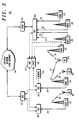
- a cell-based telephone communication system 60 in outline is shown, supporting a Universal Mobile Telecommunications Standard (UMTS) air-interface in accordance with a preferred embodiment of the invention.
- UMTS Universal Mobile Telecommunications Standard
- a plurality of subscriber units 62-66 communicate over the selected air-interface 18-21 with a plurality of Node Bs - in UMTS terminology - 22-32.
- a limited number of MSs 62-66 and Node Bs 22-32 are shown for clarity purposes only.
- the Node Bs 22-32 may be connected to external networks, for example, the public-switched telephone network (PSTN) or the Internet 34, through Radio Network Controller stations (RNC) (in UMTS terminology) 36-40 and any number of mobile switching centres (MSCs) 42 and Serving GPRS Support Nodes (SGSN) 44.
- PSTN public-switched telephone network
- RNC Radio Network Controller stations
- MSCs mobile switching centres
- SGSN Serving GPRS Support Nodes
- Each Node B 22-32 contains one or more transceiver units and communicates with the rest of the cell-based system infrastructure via the Iub interface 35.
- Each RNC 36-40 may control the operation of one or more Node Bs 22-32.
- Each MSC 42 (only one shown for clarity purposes) provides a gateway to the external network 34, whilst the SGSN 44 links to external packet networks.
- the Operations and Management Centre (OMC) 46 is operably connected to RNCs 36-40 and Node Bs 22-32 (shown only with respect to Node B 26 and Node B 28 for clarity), and administers and manages the parts of the cellular telephone communication system 60, as will be understood by those skilled in the art.
- At least one of the RNCs 36-40 has been adapted to manage and control transmissions to and from a to-be-located MS. Furthermore, the RNC 36-40 has been adapted to receive the indication from the Node B 22-32 (or BTS) of the location determination request signal transmitted on the dedicated location determination resource.
- the RNC 36-40 has been adapted to inform a number of Node B's 22-32 of such a request, or select a number of Node B's 22-32 to inform, such that location determination measurements can be calculated.
- the RNC 36-40 may instigate a load spreading procedure as described with reference to FIG. 5.
- At least one of the Node B's (or BTS) 22-32 has been adapted to be a serving Node B to receive the location request signal from the to-be-located MS, and inform the RNC 36-40 of such a request. Furthermore, the Node B may acknowledge receipt of such a request.
- control of the location determination process may, as an alternative to the RNC 36-40, be controlled in another part of the infrastructure, for example by at least one of the Node Bs 22-32 or the OMC 46.
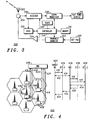
- FIG. 3 there is shown a block diagram of a subscriber unit (MS) 300 adapted to support the inventive concepts of the preferred embodiments of the present invention.
- the MS 300 contains an antenna 302 preferably coupled to a duplex filter or circulator 304 that provides isolation between receive and transmit chains within the MS 300.
- the receiver chain includes scanning receiver front-end circuitry 306 (effectively providing reception, filtering and intermediate or baseband frequency conversion).
- the scanning front-end circuit is serially coupled to a signal processing function 308.
- An output from the signal processing function is provided to a suitable output device 310, such as a screen or flat panel display.
- the receiver chain also includes received signal strength indicator (RSSI) circuitry 312, which in turn is coupled to a controller 314 for maintaining overall subscriber unit control.
- the controller 314 is also coupled to the scanning receiver front-end circuitry 306 and the signal processing function 308 (generally realised by a DSP).
- the controller 314 may therefore receive bit error rate (BER) or frame error rate (FER) data from recovered information.
- the controller is also coupled to a memory device 316 that stores operating regimes, such as decoding/encoding functions, synchronisation patterns, code sequences and the like.
- the memory device 316 stores data relating to neighbouring cell sites or systems. Furthermore, a timer 318 is operably coupled to the controller 314 to control the timing of operations (transmission or reception of time-dependent signals) within the MS 300, particularly in regard to TDD mode timing.
- this essentially includes an input device 320, such as a keypad, coupled in series through transmitter/modulation circuitry 322 and a power amplifier 324 to the antenna 302.
- the transmitter/modulation circuitry 322 and the power amplifier 324 are operationally responsive to the controller.
- scanning receiver front-end circuitry 306, the transmitter/modulation circuitry 322 and power amplifier 324, under the control and guidance of the signal processing function 308, memory device 316, timer function 318 and controller 314 have been adapted to receive and/or transmit to the infrastructure in the CLCH channel. This is performed in response to instruction from the infrastructure to enter such a mode, or as a self-initiated function decided by the controller 314 in response to a recognition of the MSs operating conditions.
- the subscriber unit 300 switches to a scanning mode of operation to receive and decode signal transmissions from neighbouring cells or systems.
- FIG. 4 a communication system and associated signalling protocol 400 for avoiding the near-far effect is shown, in accordance with a preferred embodiment of the invention.
- the up-link and down-link cases are then considered with respect to signalling and time requirements.
- indications of potential problems with a theoretical non-dedicated channel are provided.
- the Target MS 402 generates an emergency call/location determination request.
- the emergency call is transmitted 410 on an up-link channel, for example, on the random access channel (RACH).
- the serving BTS, BTS-0 404 may send an acknowledgement signal 412, back to the target MS 402 to acknowledge receipt of the emergency call.
- a near-far problem condition exists, and therefore the emergency transmission will be received only at BTS-0 404, as shown.
- the neighbours of BTS-0 404 are not informed of the situation.
- the Target MS 402 then would attempt to transmit in any time-slot (TS) hoping that the near-far problem will be weaker in one of the TS.
- TS time-slot
- BTS-0 404 Upon reception of the emergency call, BTS-0 404 informs 414 the Radio Network Controller (RNC) 436.
- the RNC 436 sends a request 416 to:
- BTS-1 406 and BTS-2 408 (case (a)) or any other selected BTS-0's neighbours (case (b)) have to inform 420 the RNC 436 about which TS will be available, for example, using the spreading load procedure of FIG. 5.
- BTS-1 406 and BTS-2 408 can communicate the TSs where Target MS can transmit after all TSs loads were checked and the load spreading procedure was performed.
- processing times in the BTS and RNC and transfer time between RNC and BS delay the location determination process.
- the amount of - signaling is excessive as BTS-1 406 and BTS-2 408 have to send the information back to RNC 436, then back to Target MS going through BTS-0 404.
- a new communication channel is proposed - termed a Common Location CHannel (CLCH).
- CLCH Common Location CHannel
- the focus of the CLCH is to reduce both the amount of signalling and the required time used in a location process.
- CLCH proposal A major benefit of the CLCH proposal is in its simplicity.
- the proposal is based upon a prior knowledge of which TS the Target MS 402 may succeed in transmitting a burst to other BTSs, initially affected by near-far interference.
- a time-slot named CLCH
- CLCH time-slot
- a Target MS 402 will initiate the emergency signal 410 on the known CLCH channel.
- the neighbouring BTSs will be informed as in the non-CLCH case.
- the main advantage is that BTS-1 406 and BTS-2 408 will now be able to immediately free up a CLCH TS.
- the emergency call signal transmitted on the up-link channel by the Target MS 402, will be also received at BTS-1 406 and BTS-2 408. Hence, both speed of the location process and signalling required are improved over the non-CLCH process.
- a guard time may be necessary after BTS-1 406 and BTS-2 408 have received the request from RNC 436, in order to better manage the communication load.
- This guard time may be known from actual traffic statistics, for example, as provided for in GSM.
- the CLCH is used for down-link traffic in normal conditions and upon reception of the request from the RNC 436, the relevant BTS simply stops transmitting on this downlink slot, thereby allowing reception on the uplink from the Target MS 402.
- FIG. 4 shows the signalling required when no channel is dedicated for a location process versus a CLCH channel approach.
- Signals 410, 414, 416 are common to both procedures, while signals 420, 422, 424 are only needed when no CLCH exists in the uplink.
- the RNC preferably determines the location of the MS in accordance with any classical location technique, such as a Remote Positioning Location Process (RPLP) for up-link transmission case.
- RPLP Remote Positioning Location Process
- BTS-0 404 is responsible for the near-far effect.
- the RNC 436 then has to reduce the power transmission of BTS-0 404 to thereby allow reception of other BTS(s) signals at the Target MS 402.
- BTS-0 404 Upon reception of an emergency signal, BTS-0 404 has to free up a TS where the other BTSs' signals may be received.
- the RNC 436 communicates 422 to BTS-0 404 the positions within the TDD frame of the broadcast channel (BCH) and synchronisation channel (SCH) for neighbouring cells of BTS-0 404.
- the RNC 436 also communicates 422 to the other BTS(s), say BTS-1 406 and BTS-2 408, the positions within the TDD frame of the broadcast channel (BCH) and synchronisation channel (SCH) for the cell of BTS-0 404.
- BTS-0 404 will simply free corresponding TS(s). If the BCH and SCH positions at the neighbouring cells of BTS-0 404 are not known (namely they are not communicated to BTS-0 404 by RNC 436), the signalling procedure is substantially the same as in the up-link case steps 410-424. Then BTS-0 will decrease the load on the TS of BTS-0 404 that correspond to the BCH (and possibly SCH) of cells covered by BTS-1 406 and BTS-2 408.
- the TDD cells are time-synchronized.
- the CLCH will be positioned on the same slot in all TDD cells.
- BTS-0 Upon reception of the emergency signal, BTS-0 will simply reduce the communication load on the CLCH slot and the other BTS(s)' signals will be automatically received at the Target MS 402.
- the down-link (DL) transmission in accordance with the preferred embodiment of the present invention, is particularly useful for a Self Positioning Location Process (SPLP).
- SPLP Self Positioning Location Process
- TS-3 522 is used, in each frame for Target MS to/from BTS-0 502 communication.
- the worst case scenario 526 corresponds to the situation when the signal transmitted in TS-3 is strongly affected at BTS-1 504 and BTS-2 506 by the interference 520 created by the "local" MSs (those power controlled respectively by BTS-1 504 and BTS-2 506 in their particular cells).
- the selection of whether to perform load spreading 516 is a radio resource management issue, generally providing freedom to the Network Operator to specify the most convenient pattern.
- the load spreading 516 was moved on TS-3 522 at BTS-1 504 to the frame N+1 510. This results in the Target MS signal being able to be received at BTS-1 504 during the (N+1)th frame 510.
- the load spreading 516 was performed only at the frame N+2 512, which made a reception of the up-link Target MS signal during the (N+2)th 512 frame possible.
Landscapes
- Engineering & Computer Science (AREA)
- Computer Networks & Wireless Communication (AREA)
- Signal Processing (AREA)
- Mobile Radio Communication Systems (AREA)
Priority Applications (1)
| Application Number | Priority Date | Filing Date | Title |
|---|---|---|---|
| EP00403712A EP1220559A1 (fr) | 2000-12-29 | 2000-12-29 | Système de communication, unité de communication et méthode de localisation |
Applications Claiming Priority (1)
| Application Number | Priority Date | Filing Date | Title |
|---|---|---|---|
| EP00403712A EP1220559A1 (fr) | 2000-12-29 | 2000-12-29 | Système de communication, unité de communication et méthode de localisation |
Publications (1)
| Publication Number | Publication Date |
|---|---|
| EP1220559A1 true EP1220559A1 (fr) | 2002-07-03 |
Family
ID=8174019
Family Applications (1)
| Application Number | Title | Priority Date | Filing Date |
|---|---|---|---|
| EP00403712A Withdrawn EP1220559A1 (fr) | 2000-12-29 | 2000-12-29 | Système de communication, unité de communication et méthode de localisation |
Country Status (1)
| Country | Link |
|---|---|
| EP (1) | EP1220559A1 (fr) |
Cited By (1)
| Publication number | Priority date | Publication date | Assignee | Title |
|---|---|---|---|---|
| US6788253B1 (en) | 2003-09-29 | 2004-09-07 | Lucent Technologies Inc. | Method and apparatus for use in improving accuracy in geo-location estimates |
Citations (3)
| Publication number | Priority date | Publication date | Assignee | Title |
|---|---|---|---|---|
| WO1998000988A2 (fr) * | 1996-07-01 | 1998-01-08 | Ericsson Inc. | Procede et appareil permettant de communiquer des informations sur la position d'une station mobile dans un reseau de telephones cellulaires |
| US6006097A (en) * | 1997-11-24 | 1999-12-21 | Telefonaktiebolaget L M Ericsson (Publ) | Method for determining position of mobile communication terminals |
| US6157842A (en) * | 1997-10-16 | 2000-12-05 | Telefonaktiebolaget Lm Ericsson | System and method for positioning a mobile station in a CDMA cellular system |
-
2000
- 2000-12-29 EP EP00403712A patent/EP1220559A1/fr not_active Withdrawn
Patent Citations (3)
| Publication number | Priority date | Publication date | Assignee | Title |
|---|---|---|---|---|
| WO1998000988A2 (fr) * | 1996-07-01 | 1998-01-08 | Ericsson Inc. | Procede et appareil permettant de communiquer des informations sur la position d'une station mobile dans un reseau de telephones cellulaires |
| US6157842A (en) * | 1997-10-16 | 2000-12-05 | Telefonaktiebolaget Lm Ericsson | System and method for positioning a mobile station in a CDMA cellular system |
| US6006097A (en) * | 1997-11-24 | 1999-12-21 | Telefonaktiebolaget L M Ericsson (Publ) | Method for determining position of mobile communication terminals |
Cited By (1)
| Publication number | Priority date | Publication date | Assignee | Title |
|---|---|---|---|---|
| US6788253B1 (en) | 2003-09-29 | 2004-09-07 | Lucent Technologies Inc. | Method and apparatus for use in improving accuracy in geo-location estimates |
Similar Documents
| Publication | Publication Date | Title |
|---|---|---|
| AU779979B2 (en) | Inter-frequency measurement and handover for wireless communications | |
| KR101119992B1 (ko) | 고속 다운링크 패킷 엑세스 링크 적응화를 위한 방법 및 장치 | |
| US9363779B2 (en) | Reducing interference in wireless time division duplex systems by monitoring and limiting timing advance | |
| US20220174528A1 (en) | Methods for flexible cli measurement reporting | |
| EP0871340B1 (fr) | Système de radiotéléphonie cellulaire avec protection contre les pertes d'appel | |
| US5722073A (en) | Method and system for measuring signals in a telecommunications systemhaving maho | |
| US6590878B1 (en) | Mobile communication system with shared time slots and frequency channels | |
| WO2005096641A1 (fr) | Procede de transfert de relais dans un systeme de communication mobile | |
| US20240259893A1 (en) | Switching method and apparatus | |
| US12015956B2 (en) | PSCell activation with early data-forwarding for dual connectivity based handover | |
| US11611892B1 (en) | Dynamic control of single-rat service based on threshold presence of dual-RAT-capable devices | |
| WO2012089082A1 (fr) | Procédé, dispositif et système d'accès sélectif à un nœud de desserte | |
| WO2024169883A1 (fr) | Gestion d'avance temporelle permettant de réduire la latence | |
| US6788253B1 (en) | Method and apparatus for use in improving accuracy in geo-location estimates | |
| US7945263B2 (en) | Mobile station handover for base stations with adaptive antenna system | |
| USRE40984E1 (en) | Reporting communication link information | |
| JP2026504505A (ja) | 通信用の方法、端末機器及びネットワーク機器 | |
| CN113382434A (zh) | 一种测量配置方法及设备 | |
| US7706798B2 (en) | Discovery of neighbour cell beacon frequencies in mobile networks | |
| EP4255021A1 (fr) | Procédés et appareil de maintenance et d'acquisition de ta pour la mobilité avec gestion de faisceau inter-cellules | |
| WO2002032011A1 (fr) | Procedes et agencement relatifs a un systeme de radiocommunication | |
| CN100450267C (zh) | 系统间连接转接的准备 | |
| WO2006110774A2 (fr) | Procede et systeme permettant d'effectuer une synchronisation de la liaison montante | |
| KR100659935B1 (ko) | 이동통신 시스템에서 핸드오버를 위한 타겟 셀 결정 방법 | |
| JP2003143069A (ja) | 送信電力制御装置および送信電力制御方法 |
Legal Events
| Date | Code | Title | Description |
|---|---|---|---|
| PUAI | Public reference made under article 153(3) epc to a published international application that has entered the european phase |
Free format text: ORIGINAL CODE: 0009012 |
|
| AK | Designated contracting states |
Kind code of ref document: A1 Designated state(s): AT BE CH CY DE DK ES FI FR GB GR IE IT LI LU MC NL PT SE TR |
|
| AX | Request for extension of the european patent |
Free format text: AL;LT;LV;MK;RO;SI |
|
| 17P | Request for examination filed |
Effective date: 20030103 |
|
| AKX | Designation fees paid |
Designated state(s): AT BE CH CY DE DK ES FI FR GB GR IE IT LI LU MC NL PT SE TR |
|
| AXX | Extension fees paid |
Extension state: AL Payment date: 20030103 Extension state: LT Payment date: 20030103 Extension state: RO Payment date: 20030103 Extension state: MK Payment date: 20030103 Extension state: SI Payment date: 20030103 Extension state: LV Payment date: 20030103 |
|
| 17Q | First examination report despatched |
Effective date: 20030306 |
|
| STAA | Information on the status of an ep patent application or granted ep patent |
Free format text: STATUS: THE APPLICATION IS DEEMED TO BE WITHDRAWN |
|
| 18D | Application deemed to be withdrawn |
Effective date: 20050701 |