EP1220568A2 - Resonanzfreie Lautsprecherbox und Verfahren zur dessen Herstellung - Google Patents
Resonanzfreie Lautsprecherbox und Verfahren zur dessen Herstellung Download PDFInfo
- Publication number
- EP1220568A2 EP1220568A2 EP01130029A EP01130029A EP1220568A2 EP 1220568 A2 EP1220568 A2 EP 1220568A2 EP 01130029 A EP01130029 A EP 01130029A EP 01130029 A EP01130029 A EP 01130029A EP 1220568 A2 EP1220568 A2 EP 1220568A2
- Authority
- EP
- European Patent Office
- Prior art keywords
- acoustic diffuser
- containing element
- monocoque
- acoustic
- loudspeaker
- Prior art date
- Legal status (The legal status is an assumption and is not a legal conclusion. Google has not performed a legal analysis and makes no representation as to the accuracy of the status listed.)
- Withdrawn
Links
Images


Classifications
-
- H—ELECTRICITY
- H04—ELECTRIC COMMUNICATION TECHNIQUE
- H04R—LOUDSPEAKERS, MICROPHONES, GRAMOPHONE PICK-UPS OR LIKE ACOUSTIC ELECTROMECHANICAL TRANSDUCERS; ELECTRIC HEARING AIDS; PUBLIC ADDRESS SYSTEMS
- H04R1/00—Details of transducers, loudspeakers or microphones
- H04R1/20—Arrangements for obtaining desired frequency or directional characteristics
- H04R1/22—Arrangements for obtaining desired frequency or directional characteristics for obtaining desired frequency characteristic only
- H04R1/28—Transducer mountings or enclosures modified by provision of mechanical or acoustic impedances, e.g. resonator, damping means
- H04R1/2869—Reduction of undesired resonances, i.e. standing waves within enclosure, or of undesired vibrations, i.e. of the enclosure itself
- H04R1/2884—Reduction of undesired resonances, i.e. standing waves within enclosure, or of undesired vibrations, i.e. of the enclosure itself by means of the enclosure structure, i.e. strengthening or shape of the enclosure
- H04R1/2888—Reduction of undesired resonances, i.e. standing waves within enclosure, or of undesired vibrations, i.e. of the enclosure itself by means of the enclosure structure, i.e. strengthening or shape of the enclosure for loudspeaker transducers
-
- H—ELECTRICITY
- H04—ELECTRIC COMMUNICATION TECHNIQUE
- H04R—LOUDSPEAKERS, MICROPHONES, GRAMOPHONE PICK-UPS OR LIKE ACOUSTIC ELECTROMECHANICAL TRANSDUCERS; ELECTRIC HEARING AIDS; PUBLIC ADDRESS SYSTEMS
- H04R1/00—Details of transducers, loudspeakers or microphones
- H04R1/20—Arrangements for obtaining desired frequency or directional characteristics
- H04R1/22—Arrangements for obtaining desired frequency or directional characteristics for obtaining desired frequency characteristic only
- H04R1/28—Transducer mountings or enclosures modified by provision of mechanical or acoustic impedances, e.g. resonator, damping means
- H04R1/2869—Reduction of undesired resonances, i.e. standing waves within enclosure, or of undesired vibrations, i.e. of the enclosure itself
- H04R1/2876—Reduction of undesired resonances, i.e. standing waves within enclosure, or of undesired vibrations, i.e. of the enclosure itself by means of damping material, e.g. as cladding
- H04R1/288—Reduction of undesired resonances, i.e. standing waves within enclosure, or of undesired vibrations, i.e. of the enclosure itself by means of damping material, e.g. as cladding for loudspeaker transducers
Definitions
- the invention concerns an acoustic diffuser, ovaloid, ellipsoid or spheroid in shape, made in a monocoque so as to eliminate the acoustic reflections, refractions and vibrations which damage the quality of the sound.
- the invention also concerns the method to produce said acoustic diffuser.
- the state of the art includes acoustic diffusers having containers composed of at least two semi-coques made of plastic material, plywood or composite materials, attached together and with a substantially box-like shape.
- Such diffusers usually comprise at least a loudspeaker able to broadcast the sound, possibly associated with a printed circuit able to support an electric-acoustic filter, for example of the crossover type, an electric connector, for example of the jack type.
- Acoustic diffusers made in this way create vibrations, reverberations, or other distortions inside, which affect the quality of the sound.
- One purpose of the invention is to achieve an acoustic diffuser which will prevent the formation of echoes, reverberations or vibrations inside it, and of refractions in the emission of sound.
- Another purpose of the invention is to achieve an acoustic diffuser which is attached so as to limit the diffusion or transmission of contact vibrations, and which can be installed easily, and positioned at different heights, and directed at an angle in space.
- Another purpose is to perfect a method which will allow to make a monocoque acoustic diffuser in a simple and efficient manner.
- the acoustic diffuser comprises a containing element formed by a monocoque and at least a loudspeaker.
- the monocoque is made from a compound of solid mineral aggregates, for example silicon, basalt and quartz, and a cohesion material, such as for example an epoxy resin, so as to limit the vibrations and to ensure a high structural density in order to optimize the frequency of resonance.
- the monocoque is substantially rounded in shape, such as for example ovaloid, ellipsoid or spheroid, in order to eliminate acoustic reflections and the formation of reverberations inside it.
- the acoustic diffuser comprises, in one embodiment, an outer covering shell composed by an abradable resin, and an inner shell formed by plastic material.
- the two shells follow the outer, respectively inner, profile of the monocoque and provide the through holes able to house the loudspeaker and/or any other electric and electronic components such as, for example, connectors, pre-printed circuits, or for acoustic devices such as for example vents to allow the air, put under pressure by the movement of the loudspeaker, to exit from the containing element.
- the acoustic diffuser also comprises support means which allow it to be fixed from above to at least one surface; in this case, they are formed by a steel cable which is inserted into a cavity of the containing element and a shock absorber element inserted between one end of the steel cable and the containing element, so as not to transmit the possible vibrations of the containing element to the surface.
- the acoustic diffuser as described heretofore is made according to the following method.
- the containing element is formed by inserting solid mineral aggregates, for example with a high level of hardness with a granulometry varying from about 1 mm to about 5 mm, inside a mold and the subsequent casting, or insertion under pressure, of a cohesion material into the same mold,'so that the resulting containing element consists of a monocoque.
- the mold has a substantially rounded inner surface, such as for example ellipsoid, ovaloid or similar, and is formed by two substantially symmetrical half-molds.
- An inner shell is positioned inside the mold, so as to define an interspace inside which the granules and the cohesion material are cast.
- an outer shell is shaped on the inner surface of the mold, so as to form, together with the inner shell, an interspace inside which the granules of hard mineral, and subsequently the cohesion material, will be inserted.
- the two half-molds are removed and the surface finishing of the monocoque, or of the outer shell, is done, the loudspeaker is assembled, and any other possible electric and electronic components or acoustic devices provided.
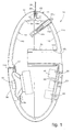
- the acoustic diffuser 10 is substantially formed by a containing element 11 and a loudspeaker 12.
- the containing element 11 is substantially ovaloid in shape, and is formed by a monocoque 11a made of a compound of granules of solid mineral such as, for example silicon and basalt, and a cohesion material such as for example an epoxy resin.
- the function of the compound is to raise the frequency of resonance with a dense and compact mass, of considerable weight, in the order of about 7 Kg, for a good physical-environmental balance, and to limit vibrations; the purpose of its shape is to eliminate the acoustic reflections and the formation of reverberations inside it.
- the containing element 11 comprises an outer shell 13, made in this case from an abradable resin, disposed on the outer surface of the monocoque 11a, and an inner shell 14 formed by two half-shells 14a and 14b, advantageously made of plastic material, disposed on opposite sides of the inner surface of the monocoque 11a.
- the outer shell 13 substantially comprises a hole 15a to house the loudspeaker 12 and to position a holed protection grid 36, of a conventional type, a hole 21b to allow the compound which constitutes the monocoque 11a to be cast, and a tubular recess 16a to allow the air moved by the action of the loudspeaker 12 to exit from the containing element 11.
- the inner half-shell 14a comprises a hole 15b disposed, during use, in correspondence with the hole 15a of the outer shell 13 and, in the upper part, a plane portion 18a able to allow a bushing 22 to be housed.
- the inner half-shell 14b comprises three holes 19 to house respective screws 20, a hole 16b disposed, during use, in correspondence with the tubular recess 16a of the outer shell 13, and able to be associated by means of glues with a tube 23, at least as long as the tubular recess 16a; moreover, the half-shell 14b comprises a through hole 24a able to couple with a mating connector support 25, advantageously made of stainless steel, and a plane portion 18b disposed during use as an extension of the corresponding plane portion 18a.
- the loudspeaker 12 is attached to the containing element 11 by means of a ring nut 17, advantageously made of stainless steel, attached to the half-shell 14a in correspondence with the hole 15b, while a printed circuit 26 for acoustic filters 27 of the crossover type is attached to the screws 20.
- the bushing 22 is buried inside the monocoque 11a, in correspondence with the plane portions 18a and 18b, and a cable 28 is attached thereto by means of a dowel screw 29.
- the cable 28 is inserted longitudinally with play into the dowel screw 29 and comprises an abutment element or stopper 31 at one end, on which a bellows-shaped rubber 30 rests; during use, the rubber 30 is able to position itself between the stopper 31 and the dowel screw 29, absorbing any possible vibrations and movements of the containing element 11.
- a mold 32 is used, formed by two half-molds 32a and 32b having respective inner surfaces 33a and 33b shaped so that, during use, they define a substantially ovaloid shape on which the outer shell 13 is shaped.
- the half-mold 32a comprises a hole 15c able to house a metal mask 15 forming the shaped hole 15a of the outer shell 13, and to support, distancing it, the inner half-shell 14a, by means of attachment screws (not shown in the drawings).
- the half-mold 32b comprises a hole 21 disposed, during use, in correspondence with the hole 21b which allows the compound to be cast, a seating 16c able to house a second metal mask 16 able to define the tubular recess 16a, and finally a last hole 24 allows to insert the connector support 25 into the hole 24a.
- the two half-shells 14a and 14b After shaping the shell 13 respectively to the surfaces 33a and 33b, after positioning the two half-shells 14a and 14b inside the mold 32, after arranging the screws 20 in the relative holes 19, after inserting the connector support 25 into the hole 24a, and after positioning the bushing 22 above the plane portions 18a and 18b, the two half-shells 14a and 14b are reciprocally attached by means of glues so as to form the shell 14.
- a structure is created by attaching the two half-molds 32a and 32b together, with inside the shell 13 and the inner shell 14 so that they form an interspace.
- the masks 15 and 16 are inserted, the tubular recess 16a is blocked with a stopper 34 and then the granules of solid mineral are inserted, simultaneously shaking the structure formed, in such a manner that the granules penetrate inside the whole interspace.
- the subsequent step includes the pouring of the cohesion material, either under pressure or in a cast, until there is a slight overflow from the hole 21b or from possible vents.
- the two half-molds 32a and 32b are dis-associated, and the loudspeaker 12, the printed circuit 26, a connector 25b and the cable 28 are assembled and electrically connected; it is also possible to line the inner part of the inner shell 14 with soundproofing material. There then follows the step of surface finishing, with sanding and painting of the outer surface of the shell 13.
- the acoustic diffuser 10 communicates with the outside only by means of the tubular recess 16a, since all the other apertures are air tight.
- tubular recess 16a is replaced by a wall 35, substantially parallel to the half-shell 14a, and open in proximity with the hole 15a of the shell 13.
- two bushings 22 are disposed on opposite sides so as to allow the containing element 11 to be attached to two opposite surfaces, in order to prevent it from oscillating.
- the solid material which makes up the monocoque 11a of the containing element 11 can consist of a metal such as aluminium, steel or otherwise.
Landscapes
- Health & Medical Sciences (AREA)
- Otolaryngology (AREA)
- Physics & Mathematics (AREA)
- Engineering & Computer Science (AREA)
- Acoustics & Sound (AREA)
- Signal Processing (AREA)
- Details Of Audible-Bandwidth Transducers (AREA)
- Obtaining Desirable Characteristics In Audible-Bandwidth Transducers (AREA)
- Pipe Accessories (AREA)
Applications Claiming Priority (2)
| Application Number | Priority Date | Filing Date | Title |
|---|---|---|---|
| IT2000UD000233A IT1315163B1 (it) | 2000-12-29 | 2000-12-29 | Diffusore acustico e metodo per la sua realizzazione |
| ITUD000233 | 2000-12-29 |
Publications (2)
| Publication Number | Publication Date |
|---|---|
| EP1220568A2 true EP1220568A2 (de) | 2002-07-03 |
| EP1220568A3 EP1220568A3 (de) | 2003-08-13 |
Family
ID=11460454
Family Applications (1)
| Application Number | Title | Priority Date | Filing Date |
|---|---|---|---|
| EP01130029A Withdrawn EP1220568A3 (de) | 2000-12-29 | 2001-12-18 | Resonanzfreie Lautsprecherbox und Verfahren zur dessen Herstellung |
Country Status (3)
| Country | Link |
|---|---|
| US (1) | US6705426B2 (de) |
| EP (1) | EP1220568A3 (de) |
| IT (1) | IT1315163B1 (de) |
Cited By (4)
| Publication number | Priority date | Publication date | Assignee | Title |
|---|---|---|---|---|
| EP1715720A1 (de) * | 2005-04-21 | 2006-10-25 | Pioneer Corporation | Teil des Vibrationssystems eines Lautsprechers und Herstellungsmethode |
| GB2428532A (en) * | 2005-07-22 | 2007-01-31 | Hosiden Besson Ltd | An acrylic resin/mineral loudspeaker cabinet |
| WO2017074200A1 (en) | 2015-10-30 | 2017-05-04 | Transverse Technology Limited | An enclosure for an audio speaker |
| CN108370463A (zh) * | 2015-10-30 | 2018-08-03 | 横向技术有限公司 | 音频扬声器的机壳 |
Families Citing this family (4)
| Publication number | Priority date | Publication date | Assignee | Title |
|---|---|---|---|---|
| US7006648B2 (en) * | 2003-10-22 | 2006-02-28 | Chao-Lang Wang | Speaker cabinet with increased air circulation efficiency |
| TWD107187S1 (zh) * | 2004-12-17 | 2005-10-21 | 瀚斯寶麗股份有限公司 | 揚聲器 |
| US7604091B2 (en) * | 2007-06-13 | 2009-10-20 | Plantronics, Inc. | Asymmetric and continuously curved speaker driver enclosure to optimize audio fidelity |
| US8857559B2 (en) * | 2011-06-14 | 2014-10-14 | Chris Reviel | Speaker cabinet and method for fabrication |
Family Cites Families (9)
| Publication number | Priority date | Publication date | Assignee | Title |
|---|---|---|---|---|
| US3720787A (en) * | 1970-03-28 | 1973-03-13 | Victor Company Of Japan | Omni-directional globular speaker system |
| ZA723011B (en) * | 1972-05-03 | 1973-08-29 | J Albertyn | A speaker enclosure |
| US3812301A (en) * | 1973-03-06 | 1974-05-21 | U Lahti | Spherical loudspeaker |
| DE2913256A1 (de) * | 1979-04-03 | 1980-10-23 | Dressler Beteiligungs Gmbh | Lautsprechergehaeuse |
| FR2616994B1 (fr) * | 1987-06-22 | 1989-11-24 | Coudoux Christian | Enceintes acoustiques a tres hautes performances |
| DE3905562C1 (de) * | 1989-02-02 | 1990-03-22 | Prodan, Hans-Joachim, 4415 Sendenhorst, De | |
| US5368270A (en) * | 1991-12-12 | 1994-11-29 | Wiwczar; Timothy V. | Speaker suspension device |
| US5661271A (en) * | 1995-06-05 | 1997-08-26 | Moser; Charles E. | Acoustic speaker enclosure having a stacked construction |
| US5731553A (en) * | 1997-01-29 | 1998-03-24 | Excel Sound & Art | Speaker system |
-
2000
- 2000-12-29 IT IT2000UD000233A patent/IT1315163B1/it active
-
2001
- 2001-12-18 EP EP01130029A patent/EP1220568A3/de not_active Withdrawn
- 2001-12-28 US US10/040,732 patent/US6705426B2/en not_active Expired - Lifetime
Cited By (9)
| Publication number | Priority date | Publication date | Assignee | Title |
|---|---|---|---|---|
| EP1715720A1 (de) * | 2005-04-21 | 2006-10-25 | Pioneer Corporation | Teil des Vibrationssystems eines Lautsprechers und Herstellungsmethode |
| US7849958B2 (en) | 2005-04-21 | 2010-12-14 | Pioneer Corporation | Vibration system part for speaker device and manufacturing method thereof |
| GB2428532A (en) * | 2005-07-22 | 2007-01-31 | Hosiden Besson Ltd | An acrylic resin/mineral loudspeaker cabinet |
| WO2017074200A1 (en) | 2015-10-30 | 2017-05-04 | Transverse Technology Limited | An enclosure for an audio speaker |
| CN108370463A (zh) * | 2015-10-30 | 2018-08-03 | 横向技术有限公司 | 音频扬声器的机壳 |
| EP3369253A4 (de) * | 2015-10-30 | 2019-07-10 | Transverse Technology Limited | Gehäuse für einen lautsprecher |
| US10623851B2 (en) | 2015-10-30 | 2020-04-14 | Transverse Technology Limited | Enclosure for an audio speaker |
| CN108370463B (zh) * | 2015-10-30 | 2020-12-15 | 横向技术有限公司 | 音频扬声器的机壳 |
| AU2016346016B2 (en) * | 2015-10-30 | 2021-02-25 | Transverse Technology Limited | An enclosure for an audio speaker |
Also Published As
| Publication number | Publication date |
|---|---|
| US20020085732A1 (en) | 2002-07-04 |
| IT1315163B1 (it) | 2003-02-03 |
| EP1220568A3 (de) | 2003-08-13 |
| US6705426B2 (en) | 2004-03-16 |
| ITUD20000233A1 (it) | 2002-06-29 |
Similar Documents
| Publication | Publication Date | Title |
|---|---|---|
| US5457291A (en) | Sound-attenuating panel | |
| US6705426B2 (en) | Acoustic diffuser and method of production | |
| MXPA06000631A (es) | Un metodo y aparato para formar una parte con amortiguador. | |
| US9208756B2 (en) | Musical instrument with aggregate shell and foam filled core | |
| US8857559B2 (en) | Speaker cabinet and method for fabrication | |
| US20080317273A1 (en) | Folded coaxial transmission line loudspeaker | |
| WO2011011524A3 (en) | Acoustic dampening for a mechanical device | |
| CN109624023A (zh) | 人造石材成型模具震动装置 | |
| WO2025175695A1 (zh) | 发声单体、发声器件及应用装置 | |
| WO2004073949A3 (en) | Filled shell devices and methods of manufacturing | |
| CA3042232C (en) | An enclosure for an audio speaker | |
| CN207802339U (zh) | 一种发声装置模组 | |
| CN110984436A (zh) | 一种隔墙板及其建筑隔墙的制备安装方法 | |
| CN108370463B (zh) | 音频扬声器的机壳 | |
| JP5276809B2 (ja) | 機械装置用架台の製造方法 | |
| CN212045208U (zh) | 一种水泥制地板模具 | |
| CN219459250U (zh) | 一种音响安装结构 | |
| SU852444A1 (ru) | Способ удалени керамическихСТЕРжНЕй из пОлОСТЕй ОТлиВОК иуСТРОйСТВО дл ЕгО ОСущЕСТВлЕНи | |
| CN222215949U (zh) | 一种扬声器的加工冶具 | |
| CN114378932B (zh) | 一种声屏板抽芯工艺 | |
| JP2009094989A (ja) | 音響吸音ダクト | |
| CN223528176U (zh) | 一种麦克风的固定装置 | |
| CN113613149B (zh) | 一种高韧性抗扭曲音盆及其制造工艺 | |
| CN2607708Y (zh) | 无悬边活塞式振动扬声器 | |
| CN201781603U (zh) | 一种高音质的陶瓷视听终端 |
Legal Events
| Date | Code | Title | Description |
|---|---|---|---|
| PUAI | Public reference made under article 153(3) epc to a published international application that has entered the european phase |
Free format text: ORIGINAL CODE: 0009012 |
|
| AK | Designated contracting states |
Kind code of ref document: A2 Designated state(s): AT BE CH CY DE DK ES FI FR GB GR IE IT LI LU MC NL PT SE TR |
|
| AX | Request for extension of the european patent |
Free format text: AL;LT;LV;MK;RO;SI |
|
| PUAL | Search report despatched |
Free format text: ORIGINAL CODE: 0009013 |
|
| AK | Designated contracting states |
Designated state(s): AT BE CH CY DE DK ES FI FR GB GR IE IT LI LU MC NL PT SE TR |
|
| AX | Request for extension of the european patent |
Extension state: AL LT LV MK RO SI |
|
| 17P | Request for examination filed |
Effective date: 20040211 |
|
| 17Q | First examination report despatched |
Effective date: 20040319 |
|
| AKX | Designation fees paid |
Designated state(s): AT BE CH CY DE DK ES FI FR GB GR IE IT LI LU MC NL PT SE TR |
|
| STAA | Information on the status of an ep patent application or granted ep patent |
Free format text: STATUS: THE APPLICATION IS DEEMED TO BE WITHDRAWN |
|
| 18D | Application deemed to be withdrawn |
Effective date: 20041001 |