EP1220582A2 - Procédé et dispositif pour la détermination de la distance entre source et détecteur dans un appareil de radiograhie numérique - Google Patents
Procédé et dispositif pour la détermination de la distance entre source et détecteur dans un appareil de radiograhie numérique Download PDFInfo
- Publication number
- EP1220582A2 EP1220582A2 EP20010310640 EP01310640A EP1220582A2 EP 1220582 A2 EP1220582 A2 EP 1220582A2 EP 20010310640 EP20010310640 EP 20010310640 EP 01310640 A EP01310640 A EP 01310640A EP 1220582 A2 EP1220582 A2 EP 1220582A2
- Authority
- EP
- European Patent Office
- Prior art keywords
- source
- detector
- ray
- exposure
- distance
- Prior art date
- Legal status (The legal status is an assumption and is not a legal conclusion. Google has not performed a legal analysis and makes no representation as to the accuracy of the status listed.)
- Withdrawn
Links
- 238000000034 method Methods 0.000 title claims abstract description 57
- 238000003384 imaging method Methods 0.000 title claims abstract description 41
- 239000011159 matrix material Substances 0.000 claims description 7
- 230000002093 peripheral effect Effects 0.000 claims description 4
- 238000013459 approach Methods 0.000 abstract description 2
- 238000000926 separation method Methods 0.000 description 8
- 230000005855 radiation Effects 0.000 description 7
- 101000840469 Arabidopsis thaliana Isochorismate synthase 1, chloroplastic Proteins 0.000 description 5
- 238000012545 processing Methods 0.000 description 5
- 238000009434 installation Methods 0.000 description 4
- 238000005259 measurement Methods 0.000 description 4
- 239000010409 thin film Substances 0.000 description 4
- 229910021417 amorphous silicon Inorganic materials 0.000 description 3
- 239000004020 conductor Substances 0.000 description 3
- 230000001105 regulatory effect Effects 0.000 description 3
- 238000004364 calculation method Methods 0.000 description 2
- 239000000758 substrate Substances 0.000 description 2
- 210000003484 anatomy Anatomy 0.000 description 1
- 230000001276 controlling effect Effects 0.000 description 1
- 238000007796 conventional method Methods 0.000 description 1
- 238000001514 detection method Methods 0.000 description 1
- 238000002405 diagnostic procedure Methods 0.000 description 1
- 230000000694 effects Effects 0.000 description 1
- 230000008030 elimination Effects 0.000 description 1
- 238000003379 elimination reaction Methods 0.000 description 1
- 239000010408 film Substances 0.000 description 1
- 238000001914 filtration Methods 0.000 description 1
- 230000006870 function Effects 0.000 description 1
- 239000011521 glass Substances 0.000 description 1
- 230000003116 impacting effect Effects 0.000 description 1
- 239000007787 solid Substances 0.000 description 1
- 238000012360 testing method Methods 0.000 description 1
Images


Classifications
-
- A—HUMAN NECESSITIES
- A61—MEDICAL OR VETERINARY SCIENCE; HYGIENE
- A61B—DIAGNOSIS; SURGERY; IDENTIFICATION
- A61B6/00—Apparatus or devices for radiation diagnosis; Apparatus or devices for radiation diagnosis combined with radiation therapy equipment
- A61B6/58—Testing, adjusting or calibrating thereof
- A61B6/588—Setting distance between source unit and detector unit
-
- A—HUMAN NECESSITIES
- A61—MEDICAL OR VETERINARY SCIENCE; HYGIENE
- A61B—DIAGNOSIS; SURGERY; IDENTIFICATION
- A61B6/00—Apparatus or devices for radiation diagnosis; Apparatus or devices for radiation diagnosis combined with radiation therapy equipment
-
- A—HUMAN NECESSITIES
- A61—MEDICAL OR VETERINARY SCIENCE; HYGIENE
- A61B—DIAGNOSIS; SURGERY; IDENTIFICATION
- A61B6/00—Apparatus or devices for radiation diagnosis; Apparatus or devices for radiation diagnosis combined with radiation therapy equipment
- A61B6/42—Arrangements for detecting radiation specially adapted for radiation diagnosis
- A61B6/4208—Arrangements for detecting radiation specially adapted for radiation diagnosis characterised by using a particular type of detector
- A61B6/4233—Arrangements for detecting radiation specially adapted for radiation diagnosis characterised by using a particular type of detector using matrix detectors
-
- A—HUMAN NECESSITIES
- A61—MEDICAL OR VETERINARY SCIENCE; HYGIENE
- A61B—DIAGNOSIS; SURGERY; IDENTIFICATION
- A61B6/00—Apparatus or devices for radiation diagnosis; Apparatus or devices for radiation diagnosis combined with radiation therapy equipment
- A61B6/58—Testing, adjusting or calibrating thereof
- A61B6/582—Calibration
- A61B6/583—Calibration using calibration phantoms
Definitions
- the present invention relates generally to digital imaging systems and, more particularly, to a calibration and setup procedure for determining a separation distance between a source and a digital detector in an imaging system.
- the installation and setup procedures for digital imaging systems can be complex and time-consuming. To comply with customer requirements and various regulatory and safety standards, such procedures generally require the determination of a variety of factors, including the accurate positioning of a x-ray source with respect to a x-ray detector. For example, the determination and establishment of fixed setpoints (or detent positions) for setting the separation distance between the x-ray source and x-ray detector and calibrating the system such that an accurate readout of the separation distance can be obtained are typical setup procedures. The determination and establishment of this separation distance, referred to as the source-to-image distance (SID), assists in appropriately controlling the size of the x-ray field during diagnostic use of the imaging system.
- SID source-to-image distance
- SID is utilized to control the size of the x-ray beam in relation to the physical size of the x-ray image receptor to minimize the amount of non-diagnostic radiation that a patient may be subject to in the course of a diagnostic procedure. Further, certain regulatory standards specify that the SID must be clearly displayed to the operator or user of the system with a certain level of accuracy.
- known installation and calibration procedures for establishing fixed SID setpoints and corresponding SID readouts require the presence of a field engineer who, through a trial and error process, calibrates the imaging system and installs fixed, preset detent positions that lock the x-ray source into various repeatable separation distances from the detector.
- the field engineer may install an electromechanical switch, or other device, in the ceiling or the superstructure of the x-ray source that indicates to the user in a tactile or otherwise perceptible manner that the x-ray source is at one of the preset SID positions.
- Many radiographic imaging systems include industry-standard SID setpoints at separation distances of, for example, 40 inches, 60 inches, and 72 inches.
- the installation and calibration procedure becomes even more complex if the detector is non-stationary.
- the field engineer may repeat the setup and calibration procedure at multiple detector positions and install several setpoint or detent devices at the corresponding multiple determined SID positions.
- the SID positions are fixed.
- a user of the imaging system is not afforded flexibility in the event that the user may desire a SID position that is non-standard. Accordingly, even though either the x-ray source or the x-ray detector could be moved to a variety of different positions such that patients of various sizes could be accommodated or various anatomical parts could be more easily imaged, the actual positions in which the x-ray source could be located with respect to the x-ray detector are restricted to only those few positions which have corresponding fixed detent setpoints.
- the present invention addresses one or more of the shortcomings noted above.
- the present technique involves calculating the SID by utilizing a known relationship. For instance, the energy delivered from a uniform source to a surface normal to an area is proportional to the area, and inversely proportional to the square of the distance from the source to the surface of the area. Using this relationship, the SID is calculated by determining the intensity generated by two separate exposures. The SID for the two exposures are unknown and may be picked randomly, however the change in the distance from the first SID to the second SID is recorded. The technique provides that once the levels of intensity are measured for the same area, the SID may be calculated using the inverse square law as recited above. In another embodiment, the intensity levels of the generated exposures are held constant and a first and second times are measured with respect to the intensity levels. The measured times are then applied to the relationship governed by the inverse square law to determine the source to image distance.
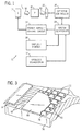
- Fig. 1 illustrates diagrammatically an imaging system 10 for acquiring and processing discrete pixel image data.
- system 10 is a digital x-ray system designed both to acquire original image data and to process the image data for display in accordance with the present technique.
- imaging system 10 includes a source of x-ray radiation 12 having a collimator 14.
- Source 12 is configured to generate an x-ray beam that passes through an opening in the collimator.
- collimator 14 permits a stream of radiation 16 to pass into a region in which a subject, such as a human patient 18 is positioned.
- a portion of the radiation 20 passes through or around the subject and impacts a digital x-ray detector, represented generally at reference numeral 22.
- detector 22 converts the x-ray photons received on its surface to lower energy photons, and subsequently to electric signals, which are acquired and processed to reconstruct an image of the features within the subject.
- imaging system 10 further includes a calculating circuit (not shown) to determine the distance from the source 12 to the detector or source to image distance (SID).
- the calculating circuit may record the intensity level of the exposure by sensing the level of exposure as well as being adapted to record time.
- Source 12 is controlled by a power supply/control circuit 24 which furnishes both power and control signals for examination sequences. It should be noted that source 12 may be movable in longitudinal, lateral, and vertical directions, such that the source can be positioned to generate an x-ray field that may be detected by a detector 22 associated with a horizontal patient positioner or a detector 22 associated with a vertical positioner. Thus, the mobility of source 12 allows source 12 to be located at any number of positions such that an x-ray beam generated by source 12 can be centered with respect to detector 22 and such that the separation distance between source 12 and detector 22 can be varied.
- detector 22 is coupled to a detector controller 26 which commands acquisition of the signals generated in the detector.
- Detector controller 26 may also execute various signal processing and filtration functions, such as for initial adjustment of dynamic ranges, interleaving of digital image data, and so forth.
- Both power supply/control circuit 24 and detector controller 26 are responsive to signals from a system controller 28.
- system controller 28 commands operation of the imaging system to execute examination protocols and to process acquired image data.
- system controller 28 also includes signal processing circuitry, typically based upon a general purpose or application-specific digital computer, associated memory circuitry for storing programs and routines executed by the computer, as well as configuration parameters and image data, interface circuits, and so forth.
- system controller 28 is linked to at least one output device, such as a display or printer as indicated at reference numeral 30.
- the output device may include standard or special purpose computer monitors and associated processing circuitry.
- One or more operator workstations 32 may be further linked in the system for outputting system parameters, requesting examinations, viewing images, and so forth.
- displays, printers, workstations, and similar devices supplied within the system may be local to the data acquisition components, or may be remote from these components, such as elsewhere within an institution or hospital, or in an entirely different location, linked to the image acquisition system via one or more configurable networks, such as the Internet, virtual private networks, and so forth.
- Fig. 2 is a diagrammatical representation of functional components of an exemplary digital detector 22.
- Fig. 2 also represents an imaging detector controller or IDC 34, which will typically be configured within detector controller 26.
- IDC 34 includes a CPU or digital signal processor, as well as memory circuits for commanding acquisition of sensed signals from the detector.
- IDC 34 is coupled via two-way fiberoptic conductors to detector control circuitry 36 within detector 22. IDC 34 thereby exchanges command signals for image data within the detector during operation.
- Detector control circuitry 36 receives DC power from a power source, represented generally at reference numeral 38. Detector control circuitry 36 is configured to originate timing and control commands for row and column drivers used to transmit signals during data acquisition phases of operation of the system. Circuitry 36 therefore transmits power and control signals to reference/regulator circuitry 40, and receives digital image pixel data from circuitry 40.
- detector 22 consists of a scintillator that converts x-ray photons received on the detector surface during examinations to lower energy (light) photons.
- An array of photodetectors then converts the light photons to electrical signals which are representative of the number of photons or the intensity of radiation impacting individual pixel regions of the detector surface.
- Readout electronics convert the resulting analog signals to digital values that can be processed, stored, and displayed, such as in a display 30 or a workstation 32 following reconstruction of the image.
- the array of photodetectors is formed on a single base of amorphous silicon. The array elements are organized in rows and columns, with each element consisting of a photodiode and a thin film transistor.
- each diode is connected to the source of the transistor, and the anodes of all diodes are connected to a negative bias voltage.
- the gates of the transistors in each row are connected together and the row electrodes are connected to the scanning electronics as described below.
- the drains of the transistors in a column are connected together and an electrode of each column is connected to readout electronics, as also described below.
- a row bus 42 includes a plurality of conductors for enabling readout from various columns of the detector, as well as for disabling rows and applying a charge compensation voltage to selected rows, where desired.
- a column bus 44 includes additional conductors for commanding readout from the columns while the rows are sequentially enabled.
- Row bus 42 is coupled to a series of row drivers 46, each of which commands enabling of a series of rows in the detector.
- readout electronics 48 are coupled to column bus 44 for commanding readout of all columns of the detector.
- row drivers 46 and readout electronics 48 are coupled to a detector panel 50 which may be subdivided into a plurality of sections 52. Each section 52 is coupled to one of the row drivers 46, and includes a number of rows. Similarly, each column driver 48 is coupled to a series of columns.
- the photodiode and thin film transistor arrangement mentioned above thereby define a series of pixels or discrete picture elements 54 which are arranged in rows 56 and columns 58.
- the rows and columns define an image matrix 60, having a height 62 and a width 64, and a known number of rows and columns.
- each pixel 54 is generally defined at a row and column crossing, at which a column electrode 68 crosses a row electrode 70.
- a thin film transistor 72 is provided at each crossing location for each pixel, as is a photodiode 74.
- signals from each photodiode may be accessed via readout electronics 48, and converted to digital signals for subsequent processing and image reconstruction.
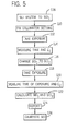
- Fig. 3 generally represents an exemplary physical arrangement of the components illustrated diagrammatically in Fig. 2.
- the detector may include a glass substrate 76 on which the components described below are disposed.
- Column electrodes 68 and row electrodes 70 are provided on the substrate and an amorphous silicon flat panel array 78 is defined, including the thin film transistors and photodiodes described above.
- a scintillator 80 is provided over the amorphous silicon array 78 for receiving radiation during examination sequences as described above.
- Contact fingers 82 are formed for communicating signals to and from the column and row electrodes, and contact leads 84 are provided for communicating the signals between the contact fingers and external circuitry.
- system 10 Before imaging system 10 may be used to perform examination sequences, system 10 is properly installed and calibrated to ensure compliance with customer needs, performance requirements, and various regulatory standards. Accurate establishment and calculation of the SID assists in appropriate control of the size of the x-ray field generated during diagnostic use of system 10. It should be noted that the setup of SID involving the establishment of SID setpoints is undesirable with respect to the present technique for calculating the SID accurately.
- x-ray source 12 is shown, which is generally mounted to a movable support structure (not shown) and positioned with respect to detector 22 which is associated with a patient positioner (not shown). Although the detector 22 is illustrated in a horizontal orientation, it should be understood that detector 22 may be positioned either horizontally or vertically depending on the type of exposure needed from the patient.
- the technique illustrated in Fig. 4 involves generating an x-ray beam at two different source positions and detection of the respective x-ray beams at the detector.
- source 12 is at a first position 12A and generates a first x-ray beam 88 that is detected by the detector 22.
- the size of the x-ray beam 88 is determined by the size of the opening in the collimator 14.
- the beam 88 impacts the detector upon an area 90, which is connected to a calculating circuit (not shown) which may be utilized to measure the intensity of the beam 88 and other parameters.
- the distance between the first source position 12A and the detector 22 corresponds to a first SID1 and referenced generally by the numeral 86.
- the source to image distance SID1 is the distance between the detector 22 and a focal spot of an x-ray beam 88 generated by source 12 while at the first source position 12A.
- X-ray beam 88 impacts the detector 22 at an impact area 90, which is illustrated by Fig. 4a.
- impact area 90 is illustrated as having a rectangular or square shape, it should be understood the impact area 90 may be curved such that the periphery of impact area 90 is circular or otherwise curvilinear.
- the area 92 within the larger detected area 90 is utilized in sensing the intensity level. For instance, row line 94 to row line 96 and column lines 98 and 100 may be selected for the specific area to be analyzed. Although, in this embodiment the area 92 is selected as such, it should be noted that a larger or smaller area may be selected and the area 92 given is only provided as an example.
- detector controller 26 and system controller 28 may determine the size of the impact area 90 and more importantly the area 92 where the intensity levels for the exposures are measured.
- a second exposure is also illustrated.
- the source 12 is moved to a second source position 12B.
- the change in the distance from the first source position 12A to the second source position 12B is referenced as ⁇ SID and by reference numeral 102.
- SID2 is the distance between detector 22 and a focal spot of an x-ray generated by source 12 while at source position 12B.
- a second x-ray beam 106 is generated by source 12 at position 12B and impacts the detector 22. It should be noted that the size of the opening of the collimator 14 remains the same with respect to the first and second exposures.
- the collimator 14 opening may be changed from the first exposure to the second exposure, however there is conveniently some common area 92 detected from the first and second exposures. Furthermore, it should be understood that the distance between the first source position 12A and the second source position 12B referenced by ⁇ SID 102 is a known quantity, (i.e. distance) whereas SID1 86 and SID2 104 remain unknown or uncalibrated quantities that may be calculated by the present technique.
- Fig. 5 illustrates a flowchart representing a method for calculating the SID utilizing the technique illustrated in Fig. 4 and 4a.
- the energy delivered from a uniform source to a surface normal to the source, of an area A is proportional to the area A, and inversely proportional to the square of the distance from the source to the surface of the area A.
- the imaging system is set to a random SID value for the first exposure, as referenced by SID1 in Fig. 4.
- the collimator 14 is calibrated accordingly to detect the exposure at a selected area 90 on the detector panel as indicated by step 110.
- the collimator 14 is set so that the detector may be adapted to detect the x-ray beam in a specified area 92 in the first and second exposures.
- step 112 a first exposure is taken and the detector detects the exposure on the selected area 90.
- the intensity E1 of the exposure is measured using the selected area 92 of the digital detector as indicated by step 114.
- the source 12 is moved to different position 12B as indicated by step 116, and the change in SID is indicated by ⁇ SID.
- the source-to-image distance after the source position is moved is referenced by SID2.
- the source 12 is moved some known distance ⁇ SID and an essentially identical exposure is executed from the source position 12B.
- the intensity E2 of the second exposure is measured as indicated by step 120.
- the SID1 value may be calculated by inputting the change in source-to-image distance ⁇ SID and the respective measured intensity levels E1 and E2. It should be understood that once the SID1 is determined, the SID2 value can be determined by either adding or subtracting the change in the distance ⁇ SID. Once the SID1 and SID2 values are calculated and reported as indicated by steps 124 and 126, the x-ray imaging system may be calibrated accordingly.
- the time T may be utilized to calculate the source-to-image distance.
- the source 12 generates an x-ray beam 88 that makes a first exposure on the detector 22.
- the elapsed time T1 for the first exposure is measured.
- the source 12 is then moved to source position 12B from source position 12A.
- a second x-ray beam 106 from source position 12B is detected by the detector 22.
- the second exposure is continued until the total intensity of the second exposure equals the intensity of the first exposure.
- the time T2 that the intensity E2 of the second exposure takes to equal the intensity of the first exposure E1 is measured.
- E1 (K*A*T1) / (SID1) ⁇ 2.
- the time may be measured and inputted within the equation as well as the change in the source-to-image distance ⁇ SID, providing the first source-to-image distance SID1 and allowing the operator to calibrate the radiographic imaging system accordingly.
- this approach conveniently makes use of the ability to measure the exposure time, and has the advantage that it may be implemented on a conventional film-based system which uses an ion chamber for exposure control.
- the exposed area can be held constant using an aperture fixed in front of the ion chamber.
- the SID may be computed by measuring the change in intensity level as a result of changing the SID and using the inverse square relationship to determine the SID.
- the inverse square relationship refers to the proportionality energy delivered from a uniform source to a surface normal to the area, and the inverse proportionality to the square of the distance from the source to the surface of the area.
- the inverse square law provides an excellent basis for calibration for a true point source of uniform intensity, and with a receptor surface which is a portion of a sphere centered on the point source.
- the error introduced by the flat detector surface and by the non-ideal focal spot source is quite small, particularly when the area of the detector used for the measurement is properly chosen, as when it represents a small solid angle from the focal spot.
Landscapes
- Health & Medical Sciences (AREA)
- Life Sciences & Earth Sciences (AREA)
- Medical Informatics (AREA)
- Engineering & Computer Science (AREA)
- Physics & Mathematics (AREA)
- Pathology (AREA)
- Public Health (AREA)
- Biophysics (AREA)
- Nuclear Medicine, Radiotherapy & Molecular Imaging (AREA)
- Optics & Photonics (AREA)
- Veterinary Medicine (AREA)
- Radiology & Medical Imaging (AREA)
- Biomedical Technology (AREA)
- Heart & Thoracic Surgery (AREA)
- Molecular Biology (AREA)
- Surgery (AREA)
- Animal Behavior & Ethology (AREA)
- General Health & Medical Sciences (AREA)
- High Energy & Nuclear Physics (AREA)
- Mathematical Physics (AREA)
- Apparatus For Radiation Diagnosis (AREA)
- Analysing Materials By The Use Of Radiation (AREA)
Applications Claiming Priority (2)
| Application Number | Priority Date | Filing Date | Title |
|---|---|---|---|
| US747541 | 2000-12-22 | ||
| US09/747,541 US6402374B1 (en) | 2000-12-22 | 2000-12-22 | Method and system for determining a source-to-image distance in a digital radiographic imaging system |
Publications (2)
| Publication Number | Publication Date |
|---|---|
| EP1220582A2 true EP1220582A2 (fr) | 2002-07-03 |
| EP1220582A3 EP1220582A3 (fr) | 2003-04-16 |
Family
ID=25005527
Family Applications (1)
| Application Number | Title | Priority Date | Filing Date |
|---|---|---|---|
| EP01310640A Withdrawn EP1220582A3 (fr) | 2000-12-22 | 2001-12-19 | Procédé et dispositif pour la détermination de la distance entre source et détecteur dans un appareil de radiograhie numérique |
Country Status (3)
| Country | Link |
|---|---|
| US (1) | US6402374B1 (fr) |
| EP (1) | EP1220582A3 (fr) |
| JP (1) | JP2002315743A (fr) |
Families Citing this family (10)
| Publication number | Priority date | Publication date | Assignee | Title |
|---|---|---|---|---|
| US6478462B2 (en) * | 2001-02-20 | 2002-11-12 | Ge Medical Systems Global Technology Company, Llc | Methodology for determining x-ray to light field decentering on digital radiographic image systems |
| US6821017B1 (en) * | 2001-08-06 | 2004-11-23 | Steven C. Tankersley | Radiated signal measuring device for radiographic imaging equipment |
| DE102005020567A1 (de) * | 2005-04-30 | 2006-11-09 | Katz, Elisabeth | Verfahren und Vorrichtung zur Online-Bestimmung des Aschegehalts einer auf einem Födermittel geförderten Substanz und Vorrichtung zur Durchführung einer Online-Analyse |
| US7463720B2 (en) * | 2006-09-12 | 2008-12-09 | Ge Security, Inc. | Systems and methods for developing a primary collimator |
| JP4946677B2 (ja) * | 2007-07-06 | 2012-06-06 | コニカミノルタホールディングス株式会社 | 透過像撮影システム、および透過像撮影方法 |
| JP6184925B2 (ja) * | 2014-09-30 | 2017-08-23 | 富士フイルム株式会社 | 放射線画像解析装置、方法、及びプログラム |
| JP6306243B2 (ja) * | 2017-05-08 | 2018-04-04 | キヤノンメディカルシステムズ株式会社 | X線診断装置 |
| CN107714065A (zh) * | 2017-09-29 | 2018-02-23 | 上海联影医疗科技有限公司 | X射线成像设备 |
| IT201800000868A1 (it) * | 2018-01-15 | 2019-07-15 | Ims Giotto S P A | Metodo di calibrazione di un collimatore e apparecchiatura per analisi a raggi x configurata per effettuare tale metodo. |
| CN110327064A (zh) * | 2019-06-19 | 2019-10-15 | 东软医疗系统股份有限公司 | 源像距检测方法、装置及设备 |
Family Cites Families (4)
| Publication number | Priority date | Publication date | Assignee | Title |
|---|---|---|---|---|
| DE2608452A1 (de) * | 1976-03-01 | 1977-09-08 | Siemens Ag | Roentgenaufnahmevorrichtung |
| EP0142841A3 (fr) * | 1983-11-18 | 1987-04-29 | Kabushiki Kaisha Toshiba | Dispositif limiteur de faisceau pour un appareil de radiodiagnostic |
| US5224145A (en) * | 1990-03-28 | 1993-06-29 | Kabushiki Kaisha Toshiba | X-ray beam limiting apparatus including pivotable blade |
| FR2737005A1 (fr) * | 1995-07-18 | 1997-01-24 | Ge Medical Syst Sa | Procede d'etalonnage geometrique d'un appareil d'imagerie |
-
2000
- 2000-12-22 US US09/747,541 patent/US6402374B1/en not_active Expired - Fee Related
-
2001
- 2001-12-19 EP EP01310640A patent/EP1220582A3/fr not_active Withdrawn
- 2001-12-21 JP JP2001388708A patent/JP2002315743A/ja not_active Withdrawn
Non-Patent Citations (1)
| Title |
|---|
| None * |
Also Published As
| Publication number | Publication date |
|---|---|
| US6402374B1 (en) | 2002-06-11 |
| EP1220582A3 (fr) | 2003-04-16 |
| JP2002315743A (ja) | 2002-10-29 |
| US20020080923A1 (en) | 2002-06-27 |
Similar Documents
| Publication | Publication Date | Title |
|---|---|---|
| EP1163880B1 (fr) | Méthode et dispositif pour determiner la distance source-image dans un système numérique d'imagerie | |
| US6478462B2 (en) | Methodology for determining x-ray to light field decentering on digital radiographic image systems | |
| JP4401752B2 (ja) | 様々な線源−画像間距離におけるx線源と検出器とを位置合わせさせる方法及び装置 | |
| EP1420618B1 (fr) | Appareil de radiographie | |
| CN1915169B (zh) | 对用于产生3d体积图像的x-射线系统中的对准误差进行检测和校正的方法和装置 | |
| US8558186B2 (en) | Radiographic image detector and gain setting method for radiographic image detector | |
| US9892521B2 (en) | Radiation image processing device and method, and radiographic imaging system | |
| US9521987B2 (en) | Radiation imaging system and operating method thereof | |
| US6402374B1 (en) | Method and system for determining a source-to-image distance in a digital radiographic imaging system | |
| US20120211666A1 (en) | Radiation image capturing system | |
| EP1341444B1 (fr) | Procede et appareil de correction de decalage electronique et de variations de gain dans un detecteur solide de rayons x | |
| JP2001243454A (ja) | アモルファス・シリコン撮像用検出器における画像残存を補償する方法及び装置 | |
| US20180335528A1 (en) | Radiographic imaging apparatus and radiographic imaging system | |
| US20020117613A1 (en) | Method of monitoring changes in the detective quantum efficiency of an x-ray detector | |
| US6402373B1 (en) | Method and system for determining a source-to-image distance in a digital imaging system | |
| US6400798B1 (en) | Simple means for measuring the offset induced by photo-conductive FETs in a solid state X-ray detector | |
| EP1157662B1 (fr) | Procédé et dispositif de détermination d'une valeur de consigne centre-à-centre latéral variable d'un système d'imagerie numérique | |
| US6879660B2 (en) | Method and apparatus for reducing spectrally-sensitive artifacts | |
| JP2020192057A (ja) | 放射線画像処理装置、画像処理方法、プログラム及び放射線撮影装置 | |
| JP6833338B2 (ja) | X線検出器 | |
| JP2001099795A (ja) | 元素マッピング装置 | |
| US6618604B2 (en) | Method and apparatus for correcting the offset induced by field effect transistor photo-conductive effects in a solid state x-ray detector | |
| JP2007215918A (ja) | X線診断装置 | |
| JPH0910191A (ja) | 放射線撮像装置 | |
| JPS6351842A (ja) | X線ct装置 |
Legal Events
| Date | Code | Title | Description |
|---|---|---|---|
| PUAI | Public reference made under article 153(3) epc to a published international application that has entered the european phase |
Free format text: ORIGINAL CODE: 0009012 |
|
| AK | Designated contracting states |
Kind code of ref document: A2 Designated state(s): AT BE CH CY DE DK ES FI FR GB GR IE IT LI LU MC NL PT SE TR |
|
| AX | Request for extension of the european patent |
Free format text: AL;LT;LV;MK;RO;SI |
|
| PUAL | Search report despatched |
Free format text: ORIGINAL CODE: 0009013 |
|
| AK | Designated contracting states |
Designated state(s): AT BE CH CY DE DK ES FI FR GB GR IE IT LI LU MC NL PT SE TR |
|
| AX | Request for extension of the european patent |
Extension state: AL LT LV MK RO SI |
|
| RIC1 | Information provided on ipc code assigned before grant |
Ipc: 7H 05G 1/26 B Ipc: 7A 61B 6/00 A |
|
| 17P | Request for examination filed |
Effective date: 20031016 |
|
| AKX | Designation fees paid |
Designated state(s): DE FR |
|
| 17Q | First examination report despatched |
Effective date: 20031218 |
|
| GRAP | Despatch of communication of intention to grant a patent |
Free format text: ORIGINAL CODE: EPIDOSNIGR1 |
|
| STAA | Information on the status of an ep patent application or granted ep patent |
Free format text: STATUS: THE APPLICATION IS DEEMED TO BE WITHDRAWN |
|
| 18D | Application deemed to be withdrawn |
Effective date: 20070726 |