EP1220727B1 - Mandrin a entrainement mecanique - Google Patents
Mandrin a entrainement mecanique Download PDFInfo
- Publication number
- EP1220727B1 EP1220727B1 EP00948871A EP00948871A EP1220727B1 EP 1220727 B1 EP1220727 B1 EP 1220727B1 EP 00948871 A EP00948871 A EP 00948871A EP 00948871 A EP00948871 A EP 00948871A EP 1220727 B1 EP1220727 B1 EP 1220727B1
- Authority
- EP
- European Patent Office
- Prior art keywords
- shank
- locking element
- opening
- slot
- locking
- Prior art date
- Legal status (The legal status is an assumption and is not a legal conclusion. Google has not performed a legal analysis and makes no representation as to the accuracy of the status listed.)
- Expired - Lifetime
Links
Images



Classifications
-
- B—PERFORMING OPERATIONS; TRANSPORTING
- B23—MACHINE TOOLS; METAL-WORKING NOT OTHERWISE PROVIDED FOR
- B23B—TURNING; BORING
- B23B31/00—Chucks; Expansion mandrels; Adaptations thereof for remote control
- B23B31/02—Chucks
- B23B31/10—Chucks characterised by the retaining or gripping devices or their immediate operating means
- B23B31/113—Retention by bayonet connection
-
- B—PERFORMING OPERATIONS; TRANSPORTING
- B23—MACHINE TOOLS; METAL-WORKING NOT OTHERWISE PROVIDED FOR
- B23B—TURNING; BORING
- B23B2260/00—Details of constructional elements
- B23B2260/136—Springs
-
- Y—GENERAL TAGGING OF NEW TECHNOLOGICAL DEVELOPMENTS; GENERAL TAGGING OF CROSS-SECTIONAL TECHNOLOGIES SPANNING OVER SEVERAL SECTIONS OF THE IPC; TECHNICAL SUBJECTS COVERED BY FORMER USPC CROSS-REFERENCE ART COLLECTIONS [XRACs] AND DIGESTS
- Y10—TECHNICAL SUBJECTS COVERED BY FORMER USPC
- Y10S—TECHNICAL SUBJECTS COVERED BY FORMER USPC CROSS-REFERENCE ART COLLECTIONS [XRACs] AND DIGESTS
- Y10S279/00—Chucks or sockets
- Y10S279/904—Quick change socket
-
- Y—GENERAL TAGGING OF NEW TECHNOLOGICAL DEVELOPMENTS; GENERAL TAGGING OF CROSS-SECTIONAL TECHNOLOGIES SPANNING OVER SEVERAL SECTIONS OF THE IPC; TECHNICAL SUBJECTS COVERED BY FORMER USPC CROSS-REFERENCE ART COLLECTIONS [XRACs] AND DIGESTS
- Y10—TECHNICAL SUBJECTS COVERED BY FORMER USPC
- Y10T—TECHNICAL SUBJECTS COVERED BY FORMER US CLASSIFICATION
- Y10T279/00—Chucks or sockets
- Y10T279/17—Socket type
- Y10T279/17128—Self-grasping
- Y10T279/17162—Yielding detent
-
- Y—GENERAL TAGGING OF NEW TECHNOLOGICAL DEVELOPMENTS; GENERAL TAGGING OF CROSS-SECTIONAL TECHNOLOGIES SPANNING OVER SEVERAL SECTIONS OF THE IPC; TECHNICAL SUBJECTS COVERED BY FORMER USPC CROSS-REFERENCE ART COLLECTIONS [XRACs] AND DIGESTS
- Y10—TECHNICAL SUBJECTS COVERED BY FORMER USPC
- Y10T—TECHNICAL SUBJECTS COVERED BY FORMER US CLASSIFICATION
- Y10T279/00—Chucks or sockets
- Y10T279/17—Socket type
- Y10T279/17761—Side detent
- Y10T279/17769—Pivoted or rotary
- Y10T279/17777—Sleeved
-
- Y—GENERAL TAGGING OF NEW TECHNOLOGICAL DEVELOPMENTS; GENERAL TAGGING OF CROSS-SECTIONAL TECHNOLOGIES SPANNING OVER SEVERAL SECTIONS OF THE IPC; TECHNICAL SUBJECTS COVERED BY FORMER USPC CROSS-REFERENCE ART COLLECTIONS [XRACs] AND DIGESTS
- Y10—TECHNICAL SUBJECTS COVERED BY FORMER USPC
- Y10T—TECHNICAL SUBJECTS COVERED BY FORMER US CLASSIFICATION
- Y10T279/00—Chucks or sockets
- Y10T279/17—Socket type
- Y10T279/17863—Shouldered-tang holding
-
- Y—GENERAL TAGGING OF NEW TECHNOLOGICAL DEVELOPMENTS; GENERAL TAGGING OF CROSS-SECTIONAL TECHNOLOGIES SPANNING OVER SEVERAL SECTIONS OF THE IPC; TECHNICAL SUBJECTS COVERED BY FORMER USPC CROSS-REFERENCE ART COLLECTIONS [XRACs] AND DIGESTS
- Y10—TECHNICAL SUBJECTS COVERED BY FORMER USPC
- Y10T—TECHNICAL SUBJECTS COVERED BY FORMER US CLASSIFICATION
- Y10T408/00—Cutting by use of rotating axially moving tool
- Y10T408/89—Tool or Tool with support
- Y10T408/907—Tool or Tool with support including detailed shank
-
- Y—GENERAL TAGGING OF NEW TECHNOLOGICAL DEVELOPMENTS; GENERAL TAGGING OF CROSS-SECTIONAL TECHNOLOGIES SPANNING OVER SEVERAL SECTIONS OF THE IPC; TECHNICAL SUBJECTS COVERED BY FORMER USPC CROSS-REFERENCE ART COLLECTIONS [XRACs] AND DIGESTS
- Y10—TECHNICAL SUBJECTS COVERED BY FORMER USPC
- Y10T—TECHNICAL SUBJECTS COVERED BY FORMER US CLASSIFICATION
- Y10T408/00—Cutting by use of rotating axially moving tool
- Y10T408/94—Tool-support
- Y10T408/95—Tool-support with tool-retaining means
Definitions
- This invention relates to a power drivable chuck, and particularly relates to a power drivable chuck having a shankresponsive locking element, and to an accessory having a shank configuration which facilitates assembly of the shank with the chuck.
- chucks are designed with an opening for receiving a shank of an accessory, such as a bit, and locking the shank with the chuck.
- the shank is inserted into an opening of a body of the chuck and a key is used to advance jaws within the body, in axial and radially inward directions to clamp about the inserted shank.
- a mechanism is contained within the opening of the body, which is responsive to the insertion of the shank therein, for operating a locking mechanism also contained within the body.
- the locking mechanism includes a rolling element, such as a ball or a roll, which is moved aside from a biased locking position by the incoming shank, and returns to the locking position when an accommodating portion of the shank is aligned with the rolling element.
- a rolling element such as a ball or a roll
- an accessory such as a bit, formed with a shank which facilitates the operation of the shank-locking features of a chuck.
- EP1128923 describes a chuck including a body in which a passage is formed.
- a locking element is moveable within the passage for locking one of a set of bits in the chuck. When a bit is inserted into the opening of the chuck, a portion of the locking element is pushed by the end of the bit rearwardly into passage to allow the bit to be inserted.
- EP1128923 falls under the provisions of Article 54(3)EPC.
- a power drivable chuck comprising the features of claim 1.
- an accessory comprising the features of claim 14.
- this invention contemplates a power drivable chuck for receiving and clamping a shank having at least one axial groove formed in the periphery thereof extending to a free end of the shank, and having a transaxial groove formed in a side wall, along an intermediate portion, of the axial groove.
- the chuck includes a body having an opening therein for receipt of the shank.
- the opening of the body is formed with a wall, and at least one axial rib formed on and extending inward from the wall of the opening of the body for receipt of the axial groove of the shank.
- a locking element is located within the opening of the body.
- Means responsive to the insertion of the free end of the shank into the opening of the body, are provided for facilitating the directing of the locking element into the axial groove of the body to allow the shank to be moved further into the opening.
- Other means responsive to an alignment of the locking element with the transaxial groove, are provided for directing the locking element into the transaxial groove to lock the shank with the chuck.
- This invention further contemplates a power drivable chuck for receiving and clamping a shank having at least one axial groove formed in the periphery thereof extending to a free end of the shank, and having a transaxial groove formed in a side wall, along an intermediate portion, of the axial groove.
- the chuck includes a body having an axis and an axial opening formed therein for receipt of the shank.
- the opening of the body is formed with a wall, with at least one axial rib formed on and extending inward from the wall of the opening of the body for receipt of the axial groove of the shank.
- a slot is formed in the body and has a first end surface at first end thereof and a second end surface at a second end thereof spaced from the first end.
- a locking element is located within the opening of the body and has a portion thereof located within the slot for movement relative thereto within a plane between the first end surface and the second surface of the slot.
- a biasing element is provided for normally urging the locking element into engagement with the first end surface and allowing movement of the locking element toward the second end surface upon the application of a force sufficient to overcome an urging force as applied by the biasing element.
- this invention contemplates an accessory with a shank having an axis and a free end.
- An axial groove is formed in the shank through the free end thereof, and the axial groove is formed with a wall.
- a transaxial groove is formed in the wall of the axial groove at a location spaced inboard from the free end of the shank.
- a chuck 30 can be coupled to a power driver such as, for example, a drill 32, shown in phantom, for rotating the chuck.
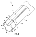
- the chuck 30 is designed with a shank-receiving opening 34 for receiving and locking a bit 36, as shown in Fig. 2 , having a shank 38 with a plurality of spaced, axially-aligned ribs 40, separated by a plurality of axially-aligned grooves 42.
- a free, or rear, end of each of the ribs 40 is formed with a slanting surface 44 ( Fig. 6 ), which slants forwardly from a first side edge 46 to a second edge 48 of the rear end of the rib.
- Each of the ribs 40 is formed with a transaxial groove 50, where all of the grooves are located in a common plane perpendicular to the axis of the bit 36.
- a plurality of bits, having ribs and grooves formed in the shanks, are disclosed in EP1128923 .
- the ribs of the bits disclosed in the above-noted pending patent application may be modified by the formation of a groove, such as the groove 50, to facilitate insertion and locking of the modified bits in the chuck 30.
- the chuck 30 includes a chuck body 52 formed with a plurality of spaced ribs 54, which extend radially inward from an inner wall of the shank-receiving opening 34, with grooves 56 between the ribs.
- the chuck disclosed in the above-identified pending patent application is formed with ribs and grooves in a similar arrangement.
- the chuck body 52 includes three slots 58, each of which is formed.radially through a cylindrical wall 60 of the body adjacent an inboard end of the respective ribs 54 of the body and in a common plane 61 perpendicular to the axis of the body.
- a small hole 62 is formed through the wall 60 of the body at a location to the rear of the plane 61 of the slots 58.
- a latching unit 64 is formed with a movable external element, such as a circular band 66, which is located about the chuck body 52 radially outward of the slots 58, and is further formed with a plurality of locking elements, such as three spaced locking fingers 68, extending radially inward from an inside wall of the band.
- Each of the locking fingers 68 is located within a respective one of the slots 58, as shown in Figs. 3, 4 and 5 , and is movable angularly in the plane 61 between opposite ends of the respective slot.
- a coil spring 70 is located within the opening 34 of the chuck body 52, just rearward of the plane 61.
- the spring 70 is formed with a straight forward end 72, which is located in a small hole in an intermediate portion of one of the locking fingers 68, and a straight rearward end 74, which is located in the opening 62 of the chuck body 52.
- each of the locking fingers 68 is at one end of the respective one of the slots 58, which precludes movement of the band 66 and the fingers in a counterclockwise direction. Also, each of the locking fingers 68 is aligned with, and to the rear of, the slanted surface 44 of a respective one of the ribs 40 of the shank 38.
- each rib 40 engages the respective finger 68 and moves the finger, and the band 66 , in a rotary direction within the plane 61, whereby the spring 70 is being wound in a tensioning direction.
- the fingers 68 are moved angularly in the plane 61 to a position of alignment with a respective one of the grooves 42 of the shank 38, as shown in Fig. 5 .
- the grooves 42 of the shank 38 allow the continued rearward movement of the shank by providing a clear path for the shank past the respective locking fingers 68, which remain in the plane 61.
- the side walls of the grooves 42 restrain the fingers from moving angularly within the plane 61, whereby the spring 70 remains in the tensioned condition.
- the relative axial movement of the grooves 42 of the shank 38 and the fingers 68 is represented in Fig. 6 by the dashed line finger 68a, it being understood that the finger 68a has remained in the plane 61.
- the transaxial groove 50 of the shank is eventually aligned with the plane 61, where the locking fingers 68 are now free of the restraints of the grooves 42 thereon.
- the tensioned spring 70 relaxes to move the locking fingers 68 in a clockwise direction to the limit of the opposite ends of the respective slots 58.
- the fingers 68 are moved into respective ones of the transaxial grooves 50 of the shank 38.
- this movement of the fingers 68 is represented by the dashed line finger 68b in Fig. 6 , it being understood that the finger 68b has remained in the plane 61.
- the bit 3 6 is now locked with the chuck 30, whereby axial movement of the bit relative to the chuck body 52 is precluded as long as the locking fingers 68 remain in the transaxial groove 50.
- the operator When the operator desires to remove the bit 3 6 from the chuck 30, the operator turns the band 66 by hand to move the locking fingers 68 out of the transaxial groove 50 and into alignment with the grooves 42 of the shank 38. The bit 36 can now be withdrawn from the chuck 30.
- the axial width of the transaxial groove 5 0 of the shank 38 can be slightly wider than the width of the locking fingers 68 to provide a firm lock for use of the bit 36, for example, in a rotary drilling operation.
- the transaxial groove 50 of the shank 38 can be somewhat wider than the width of the locking fingers 68 to allow some axial movement of the bit 36, for example, in a hammering or hammer drilling operation.
Landscapes
- Engineering & Computer Science (AREA)
- Mechanical Engineering (AREA)
- Gripping On Spindles (AREA)
- Pharmaceuticals Containing Other Organic And Inorganic Compounds (AREA)
- Power Steering Mechanism (AREA)
- Polishing Bodies And Polishing Tools (AREA)
Claims (14)
- Mandrin à entraînement mécanique (30) pour recevoir et serrer une tige (38) ayant au moins une rainure axiale (42) formée dans sa périphérie, s'étendant jusqu'à une extrémité libre (40) de la tige, et ayant une rainure transaxiale (50) formée dans une paroi latérale, le long d'une partie intermédiaire de la rainure axiale, qui comprend :un corps (52) ayant une ouverture (34) à l'intérieur de celui-ci pour la réception de la tige ;l'ouverture du corps formée avec une paroi ;au moins une nervure axiale (54) formée sur et s'étendant vers l'intérieur à partir de la paroi de l'ouverture du corps pour la réception de la rainure axiale (42) de la tige ;un élément de verrouillage (68) situé dans l'ouverture du corps ;dans lequel l'élément de verrouillage (68) est adapté pour tourner en réponse à l'insertion de l'extrémité libre de la tige dans l'ouverture du corps, afin de faciliter la direction de l'élément de verrouillage dans la rainure axiale de la tige afin de permettre à la tige de continuer à se déplacer dans l'ouverture ; et
des moyens (70) sensibles à un alignement de l'élément de verrouillage avec la rainure transaxiale, pour diriger l'élément de verrouillage dans la rainure transaxiale afin de bloquer la tige avec le mandrin. - Mandrin à entraînement mécanique selon la revendication 1, qui comprend en outre :l'ouverture et la nervure, étant chacune d'une taille et d'une configuration prédéterminée pour la réception et le maintien de la tige pouvant être montée sur le mandrin de l'une quelconque parmi une pluralité de tiges ayant différentes dimensions transaxiales externes.
- Mandrin à entraînement mécanique selon la revendication 1 ou 2, qui comprend en outre :l'élément de verrouillage qui est normalement décalé de manière circonférentielle de la nervure axiale du corps.
- Mandrin à entraînement mécanique selon l'une quelconque des revendications précédentes, qui comprend en outre :l'élément de verrouillage qui est confiné pour le mouvement angulaire uniquement dans un plan (61) perpendiculaire à un axe de l'ouverture du corps.
- Mandrin à entraînement mécanique selon l'une quelconque des revendications précédentes, qui comprend en outre :une surface de butée formée sur le corps;l'élément de verrouillage étant poussé de manière sollicitée et normalement en mise en prise avec la surface de butée pour positionner l'élément de verrouillage pour l'initiation du mouvement de l'élément de verrouillage suite à l'insertion de la tige dans l'ouverture du corps.
- Mandrin à entraînement mécanique selon l'une quelconque des revendications précédentes, dans lequel les moyens de facilitation comprennent :l'élément de verrouillage formé avec une surface positionnée pour la mise en prise avec l'extrémité libre de la tige suite à son insertion dans l'ouverture du corps ;l'élément de verrouillage étant monté à l'intérieur du corps pour le mouvement rotatif ; etun élément de sollicitation (70) en mise en prise avec l'élément de verrouillage pour pousser de manière continue l'élément de verrouillage dans une direction prédéterminée.
- Mandrin à entraînement mécanique selon l'une quelconque des revendications précédentes, dans lequel les moyens de direction comprennent :l'élément de verrouillage qui est monté à l'intérieur du corps pour le mouvement de rotation ; etun élément de sollicitation (70) en mise en prise avec l'élément de verrouillage pour pousser normalement l'élément de verrouillage dans une direction prédéterminée.
- Mandrin à entraînement mécanique selon la revendication 1, qui comprend en outre :une fente (58) formée à travers le corps ;un élément externe mobile (66) situé à l'extérieur du corps de manière adjacente à la fente formée à travers celui-ci ;l'élément de verrouillage étant formé sur l'élément externe mobile et s'étendant vers l'intérieur à partir de celui-ci et à travers la fente formée dans le corps.
- Mandrin à entraînement mécanique selon l'une quelconque des revendications précédentes, qui comprend en outre :une fente (58) formée à travers le corps ;l'élément de verrouillage étant positionné à l'intérieur de la fente pour le mouvement par rapport à celle-ci ;la fente étant formée avec une longueur radiale suffisante pour permettre à l'élément de verrouillage d'être déplacé entre une position verrouillée et une position déverrouillée.
- Mandrin à entraînement mécanique selon la revendication 8 ou 9, dans lequel :la fente a une première surface d'extrémité au niveau de sa première extrémité et une seconde surface d'extrémité au niveau de sa seconde surface d'extrémité espacée de la première extrémité ;l'élément de verrouillage est situé à l'intérieur de l'ouverture du corps et a sa partie située à l'intérieur de la fente pour le mouvement par rapport à celle-ci à l'intérieur d'un plan (61) entre la première surface d'extrémité et la seconde surface de la fente ; etl'élément de sollicitation pousse normalement l'élément de verrouillage en mise en prise avec la première surface d'extrémité et permettant le mouvement de l'élément de verrouillage vers la seconde surface d'extrémité suite à l'application d'une force suffisante pour venir à bout d'une force de poussée, telle qu'appliquée par l'élément de sollicitation.
- Mandrin à entraînement mécanique selon la revendication 10, qui comprend en outre :l'élément de verrouillage qui est formé avec une surface qui est normalement positionnée pour mettre en prise et être sensible à l'extrémité libre de la tige qui est insérée dans l'ouverture du corps pour mettre en prise l'élément de verrouillage d'une première position à une seconde position.
- Mandrin à entraînement mécanique selon la revendication 10 ou 11, qui comprend en outre :une fente qui est une première fente formée à travers le corps dans le plan qui est un plan transaxial (61) ;au moins une seconde fente formée dans le corps dans le plan transaxial et espacée de la première fente ;l'élément de verrouillage est un premier élément de verrouillage ;au moins un second élément de verrouillage positionné à l'intérieur de l'ouverture du corps et ayant sa partie positionnée à l'intérieur d'au moins la seconde fente pour le mouvement par rapport à celle-ci dans le plan transaxial entre la première surface d'extrémité et la seconde surface d'extrémité de la fente ;l'élément de sollicitation poussant normalement le premier élément de verrouillage et au moins le second élément de verrouillage en mise en prise avec les premières surfaces d'extrémité respectives et permettant le mouvement des éléments de verrouillage vers les secondes surfaces d'extrémité respectives suite à l'application d'une force suffisante pour venir à bout d'une force de poussée telle qu'appliquée par l'élément de sollicitation.
- Mandrin à entraînement mécanique selon la revendication 12, qui comprend en outre :une bande circulaire (66) située à l'extérieur du corps dans le plan transaxial et mobile par rapport au corps ;les éléments de verrouillage (68) étant formés sur la bande circulaire au niveau de leurs emplacements espacés et s'étendant vers l'intérieur à partir de celle-ci et à travers les fentes respectives, moyennant quoi les éléments de verrouillage sont mobiles dans les fentes respectives suite au mouvement de la bande circulaire.
- Accessoire (36), qui comprend :une tige (38) ayant au moins une rainure axiale (42) formée dans sa périphérie, s'étendant jusqu'à une extrémité libre (40) de la tige, et ayant une rainure transaxiale (50) formée dans une paroi latérale, le long d'une partie intermédiaire de la rainure axiale ; etl'extrémité libre de la tige étant formée avec au moins une surface d'inclinaison (44) qui s'incline à partir d'un premier bord (46) au niveau d'un premier côté de la tige jusqu' à un second bord (48) au niveau d'un second côté de la tige situé généralement à l'opposé du premier côté de la tige.
Applications Claiming Priority (3)
| Application Number | Priority Date | Filing Date | Title |
|---|---|---|---|
| US14482799P | 1999-07-21 | 1999-07-21 | |
| US144827P | 1999-07-21 | ||
| PCT/US2000/019945 WO2001007186A1 (fr) | 1999-07-21 | 2000-07-21 | Mandrin a entrainement mecanique |
Publications (3)
| Publication Number | Publication Date |
|---|---|
| EP1220727A1 EP1220727A1 (fr) | 2002-07-10 |
| EP1220727A4 EP1220727A4 (fr) | 2004-12-15 |
| EP1220727B1 true EP1220727B1 (fr) | 2008-12-24 |
Family
ID=22510324
Family Applications (1)
| Application Number | Title | Priority Date | Filing Date |
|---|---|---|---|
| EP00948871A Expired - Lifetime EP1220727B1 (fr) | 1999-07-21 | 2000-07-21 | Mandrin a entrainement mecanique |
Country Status (7)
| Country | Link |
|---|---|
| US (1) | US6390739B1 (fr) |
| EP (1) | EP1220727B1 (fr) |
| CN (2) | CN1597202A (fr) |
| AT (1) | ATE418410T1 (fr) |
| AU (1) | AU6230600A (fr) |
| DE (1) | DE60041200D1 (fr) |
| WO (1) | WO2001007186A1 (fr) |
Families Citing this family (26)
| Publication number | Priority date | Publication date | Assignee | Title |
|---|---|---|---|---|
| EP1218135A4 (fr) * | 1999-07-21 | 2004-12-15 | Black & Decker Inc | Mandrin a entrainement mecanique |
| DE10058587A1 (de) * | 2000-11-25 | 2002-05-29 | Hilti Ag | Vorrichtung zur Drehmomentübertragung |
| US20030078311A1 (en) | 2001-10-19 | 2003-04-24 | Ulrich Muller | Process for the alkoxylation of organic compounds in the presence of novel framework materials |
| DE20203129U1 (de) * | 2002-02-27 | 2002-05-08 | Quanz, Reiner, 42859 Remscheid | Rotierendes Werkzeug mit einem Einspannschaft |
| ATE460255T1 (de) * | 2003-11-26 | 2010-03-15 | Hilti Ag | Werkzeugaufnahme für ein drehendes und schlagendes werkzeug |
| US7354230B2 (en) | 2003-12-23 | 2008-04-08 | Lynn Bauman | Bit holding apparatus for use with a power tool |
| US8132990B2 (en) * | 2003-12-23 | 2012-03-13 | Lynn Everett Bauman | Bit holding apparatus for use with a power tool |
| US7752946B2 (en) * | 2006-04-04 | 2010-07-13 | Shyh-Ming Wang | Socket for wrenches |
| US20070227311A1 (en) * | 2006-04-04 | 2007-10-04 | Shyh-Ming Wang | Socket for a wrench |
| USD579033S1 (en) * | 2007-10-25 | 2008-10-21 | Hougen Manufacturing, Inc. | Annular cutter |
| EP2214856B1 (fr) | 2007-11-29 | 2016-04-13 | Airbus Operations GmbH | Procédé de codage d'un dispositif de perçage |
| US8622401B2 (en) * | 2009-02-27 | 2014-01-07 | Black & Decker Inc. | Bit retention device |
| US8381830B2 (en) | 2009-05-05 | 2013-02-26 | Black & Decker Inc. | Power tool with integrated bit retention device |
| US8800999B2 (en) * | 2009-02-27 | 2014-08-12 | Black & Decker Inc. | Bit retention device |
| CN201446519U (zh) * | 2009-06-05 | 2010-05-05 | 南京德朔实业有限公司 | 电动工具 |
| CN102059569A (zh) * | 2010-10-29 | 2011-05-18 | 无锡迪奥机械有限公司 | 自动车床的夹紧夹头 |
| EP2749367B1 (fr) * | 2011-08-22 | 2017-10-11 | MST Corporation | Support d'outil à ajustement fretté |
| US9505108B2 (en) | 2012-02-15 | 2016-11-29 | Black & Decker Inc. | Bit holder with floating magnet sleeve |
| US9227309B2 (en) | 2012-02-15 | 2016-01-05 | Black & Decker Inc. | Quick change bit holder with ring magnet |
| US9943946B2 (en) | 2012-02-15 | 2018-04-17 | Black & Decker Inc. | Tool bits with floating magnet sleeves |
| US9156147B2 (en) | 2012-02-15 | 2015-10-13 | Black & Decker Inc. | Quick change bit holder with ring magnet |
| US10150205B2 (en) | 2012-02-15 | 2018-12-11 | Black & Decker Inc. | Fastening tools with floating magnet sleeves |
| USD789761S1 (en) | 2015-11-02 | 2017-06-20 | Black & Decker Inc. | Torsion bit |
| AT15846U1 (de) * | 2017-03-14 | 2018-07-15 | Ceratizit Austria Gmbh | Schneidwerkzeug für die rotatorische Bearbeitung eines Werkstücks |
| EP3424645B1 (fr) * | 2017-07-07 | 2021-05-05 | Von Arx AG | Accouplement destiné à relier une tête de changement d'outil à une partie d'un appareil de presse |
| CN110449605B (zh) * | 2019-07-03 | 2021-02-12 | 广州通发智能装备股份有限公司 | 一种高稳固加工的数控车床 |
Family Cites Families (13)
| Publication number | Priority date | Publication date | Assignee | Title |
|---|---|---|---|---|
| US1034723A (en) * | 1911-04-01 | 1912-08-06 | Mueller Mfg Co H | Tool-retaining device for boring-bars. |
| US1138465A (en) | 1914-11-19 | 1915-05-04 | North Bros Mfg Co | Chuck. |
| US1311961A (en) * | 1918-05-31 | 1919-08-05 | Gairing Needham Tool Co Inc | Gage for floating-tool holders. |
| US1413101A (en) * | 1920-08-27 | 1922-04-18 | Samuel J Cushing | Tool holder |
| US2387339A (en) * | 1943-08-21 | 1945-10-23 | George J Meyer | Chuck |
| US2393424A (en) * | 1945-01-11 | 1946-01-22 | Howard I Selch | Boring or like tool |
| US5340245A (en) | 1990-10-16 | 1994-08-23 | Robert Bosch Gmbh | Device on portable machine tools |
| US5316323A (en) * | 1993-01-08 | 1994-05-31 | Victor Jovanovic | Two-part tool holding fixture |
| US5398946A (en) * | 1993-12-29 | 1995-03-21 | Poly-Tech Industries | Chuck having one-step lock and release |
| FR2748304B1 (fr) * | 1996-05-02 | 1998-06-26 | Lemforder Nacam Sa | Dispositif d'accouplement de deux arbres |
| US6053675A (en) * | 1998-06-26 | 2000-04-25 | Black & Decker Inc. | Quick-acting tool bit holder |
| US6053765A (en) * | 1998-10-16 | 2000-04-25 | Lear Automotive Dearborn, Inc. | Electrical connector incorporating a light |
| DE69938838D1 (de) * | 1998-11-12 | 2008-07-10 | Black & Decker Inc | Futter, bohrer, zusammenbau dafür und montagemethode |
-
2000
- 2000-07-21 EP EP00948871A patent/EP1220727B1/fr not_active Expired - Lifetime
- 2000-07-21 AT AT00948871T patent/ATE418410T1/de not_active IP Right Cessation
- 2000-07-21 AU AU62306/00A patent/AU6230600A/en not_active Abandoned
- 2000-07-21 CN CN200410085623.XA patent/CN1597202A/zh active Pending
- 2000-07-21 CN CN00813137.6A patent/CN1250365C/zh not_active Expired - Fee Related
- 2000-07-21 US US09/621,083 patent/US6390739B1/en not_active Expired - Fee Related
- 2000-07-21 DE DE60041200T patent/DE60041200D1/de not_active Expired - Fee Related
- 2000-07-21 WO PCT/US2000/019945 patent/WO2001007186A1/fr not_active Ceased
Also Published As
| Publication number | Publication date |
|---|---|
| DE60041200D1 (de) | 2009-02-05 |
| ATE418410T1 (de) | 2009-01-15 |
| EP1220727A4 (fr) | 2004-12-15 |
| WO2001007186A1 (fr) | 2001-02-01 |
| AU6230600A (en) | 2001-02-13 |
| CN1374896A (zh) | 2002-10-16 |
| US6390739B1 (en) | 2002-05-21 |
| CN1250365C (zh) | 2006-04-12 |
| CN1597202A (zh) | 2005-03-23 |
| EP1220727A1 (fr) | 2002-07-10 |
Similar Documents
| Publication | Publication Date | Title |
|---|---|---|
| EP1220727B1 (fr) | Mandrin a entrainement mecanique | |
| US6533291B2 (en) | Chuck having quick change mechanism | |
| US6488451B1 (en) | Drive shaft lock | |
| US6517088B1 (en) | Lockable drill chuck | |
| US4184692A (en) | Motor quick-change chuck system for tool having cylindrically shaped adapter portion | |
| US4188041A (en) | Motor quick-change chuck system for tool having cylindrically shaped adapter portion | |
| US4395170A (en) | Drill, drill chuck, and methods of chucking and unchucking | |
| US4234277A (en) | Motor quick-change chuck system for tool having cylindrically shaped adapter portion | |
| US6902358B2 (en) | Power drivable chuck | |
| US6092814A (en) | Tool holder for inserted tools in drilling and/or hammering machines | |
| US7654779B2 (en) | Power tool | |
| US7469909B2 (en) | Chuck for receiving tools operated by rotating around the axis thereof | |
| EP1857209B1 (fr) | Dispositif de serrage de lames sans outil pour un outil à mouvement alternatif | |
| US5988957A (en) | Quick clamp | |
| EP1534453B1 (fr) | Mecanisme de mandrin a connexion rapide | |
| US20020037201A1 (en) | Plug ejecting hole saw with twist-locking interchangeable saw cups | |
| US20040146367A1 (en) | Guide mechanism for power drill | |
| US20090160138A1 (en) | Tool holder for a machine tool, in particular for a hand-held power tool | |
| US4273344A (en) | Motor quick-change chuck system for tool having cylindrically shaped adapter portion | |
| US5129662A (en) | Chuck | |
| US7431308B2 (en) | Tool-holding chuck for equipping a rotating machine, provided with sequenced radial and axial locking means | |
| US6343903B1 (en) | Tool holder of hollow taper shank in tool machine | |
| EP1285711B1 (fr) | Port-outil pour une machine-outil | |
| JPH0775907A (ja) | 手持穿孔機、殊にハンマドリル並びに手持穿孔機のための工具保持体 | |
| US6402160B1 (en) | Chuck with improved bearing |
Legal Events
| Date | Code | Title | Description |
|---|---|---|---|
| PUAI | Public reference made under article 153(3) epc to a published international application that has entered the european phase |
Free format text: ORIGINAL CODE: 0009012 |
|
| 17P | Request for examination filed |
Effective date: 20020220 |
|
| AK | Designated contracting states |
Kind code of ref document: A1 Designated state(s): AT BE CH CY DE DK ES FI FR GB GR IE IT LI LU MC NL PT SE |
|
| AX | Request for extension of the european patent |
Free format text: AL;LT;LV;MK;RO;SI |
|
| A4 | Supplementary search report drawn up and despatched |
Effective date: 20041028 |
|
| RIC1 | Information provided on ipc code assigned before grant |
Ipc: 7B 23B 31/113 B Ipc: 7B 23B 31/103 A |
|
| 17Q | First examination report despatched |
Effective date: 20060316 |
|
| GRAP | Despatch of communication of intention to grant a patent |
Free format text: ORIGINAL CODE: EPIDOSNIGR1 |
|
| GRAS | Grant fee paid |
Free format text: ORIGINAL CODE: EPIDOSNIGR3 |
|
| GRAA | (expected) grant |
Free format text: ORIGINAL CODE: 0009210 |
|
| AK | Designated contracting states |
Kind code of ref document: B1 Designated state(s): AT BE CH CY DE DK ES FI FR GB GR IE IT LI LU MC NL PT SE |
|
| REG | Reference to a national code |
Ref country code: GB Ref legal event code: FG4D |
|
| REG | Reference to a national code |
Ref country code: CH Ref legal event code: EP |
|
| REG | Reference to a national code |
Ref country code: IE Ref legal event code: FG4D |
|
| REF | Corresponds to: |
Ref document number: 60041200 Country of ref document: DE Date of ref document: 20090205 Kind code of ref document: P |
|
| PG25 | Lapsed in a contracting state [announced via postgrant information from national office to epo] |
Ref country code: FI Free format text: LAPSE BECAUSE OF FAILURE TO SUBMIT A TRANSLATION OF THE DESCRIPTION OR TO PAY THE FEE WITHIN THE PRESCRIBED TIME-LIMIT Effective date: 20081224 Ref country code: NL Free format text: LAPSE BECAUSE OF FAILURE TO SUBMIT A TRANSLATION OF THE DESCRIPTION OR TO PAY THE FEE WITHIN THE PRESCRIBED TIME-LIMIT Effective date: 20081224 |
|
| NLV1 | Nl: lapsed or annulled due to failure to fulfill the requirements of art. 29p and 29m of the patents act | ||
| PG25 | Lapsed in a contracting state [announced via postgrant information from national office to epo] |
Ref country code: BE Free format text: LAPSE BECAUSE OF FAILURE TO SUBMIT A TRANSLATION OF THE DESCRIPTION OR TO PAY THE FEE WITHIN THE PRESCRIBED TIME-LIMIT Effective date: 20081224 Ref country code: ES Free format text: LAPSE BECAUSE OF FAILURE TO SUBMIT A TRANSLATION OF THE DESCRIPTION OR TO PAY THE FEE WITHIN THE PRESCRIBED TIME-LIMIT Effective date: 20090404 |
|
| PG25 | Lapsed in a contracting state [announced via postgrant information from national office to epo] |
Ref country code: SE Free format text: LAPSE BECAUSE OF FAILURE TO SUBMIT A TRANSLATION OF THE DESCRIPTION OR TO PAY THE FEE WITHIN THE PRESCRIBED TIME-LIMIT Effective date: 20090324 Ref country code: PT Free format text: LAPSE BECAUSE OF FAILURE TO SUBMIT A TRANSLATION OF THE DESCRIPTION OR TO PAY THE FEE WITHIN THE PRESCRIBED TIME-LIMIT Effective date: 20090525 Ref country code: AT Free format text: LAPSE BECAUSE OF FAILURE TO SUBMIT A TRANSLATION OF THE DESCRIPTION OR TO PAY THE FEE WITHIN THE PRESCRIBED TIME-LIMIT Effective date: 20081224 |
|
| PG25 | Lapsed in a contracting state [announced via postgrant information from national office to epo] |
Ref country code: DK Free format text: LAPSE BECAUSE OF FAILURE TO SUBMIT A TRANSLATION OF THE DESCRIPTION OR TO PAY THE FEE WITHIN THE PRESCRIBED TIME-LIMIT Effective date: 20081224 |
|
| PLBE | No opposition filed within time limit |
Free format text: ORIGINAL CODE: 0009261 |
|
| STAA | Information on the status of an ep patent application or granted ep patent |
Free format text: STATUS: NO OPPOSITION FILED WITHIN TIME LIMIT |
|
| PGFP | Annual fee paid to national office [announced via postgrant information from national office to epo] |
Ref country code: GB Payment date: 20090727 Year of fee payment: 10 Ref country code: DE Payment date: 20090729 Year of fee payment: 10 |
|
| 26N | No opposition filed |
Effective date: 20090925 |
|
| PG25 | Lapsed in a contracting state [announced via postgrant information from national office to epo] |
Ref country code: MC Free format text: LAPSE BECAUSE OF NON-PAYMENT OF DUE FEES Effective date: 20090731 |
|
| REG | Reference to a national code |
Ref country code: CH Ref legal event code: PL |
|
| REG | Reference to a national code |
Ref country code: FR Ref legal event code: ST Effective date: 20100331 |
|
| REG | Reference to a national code |
Ref country code: IE Ref legal event code: MM4A |
|
| PG25 | Lapsed in a contracting state [announced via postgrant information from national office to epo] |
Ref country code: FR Free format text: LAPSE BECAUSE OF NON-PAYMENT OF DUE FEES Effective date: 20090731 Ref country code: CH Free format text: LAPSE BECAUSE OF NON-PAYMENT OF DUE FEES Effective date: 20090731 Ref country code: LI Free format text: LAPSE BECAUSE OF NON-PAYMENT OF DUE FEES Effective date: 20090731 |
|
| PGFP | Annual fee paid to national office [announced via postgrant information from national office to epo] |
Ref country code: IT Payment date: 20090728 Year of fee payment: 10 |
|
| PG25 | Lapsed in a contracting state [announced via postgrant information from national office to epo] |
Ref country code: IE Free format text: LAPSE BECAUSE OF NON-PAYMENT OF DUE FEES Effective date: 20090721 |
|
| PG25 | Lapsed in a contracting state [announced via postgrant information from national office to epo] |
Ref country code: GR Free format text: LAPSE BECAUSE OF FAILURE TO SUBMIT A TRANSLATION OF THE DESCRIPTION OR TO PAY THE FEE WITHIN THE PRESCRIBED TIME-LIMIT Effective date: 20090325 |
|
| GBPC | Gb: european patent ceased through non-payment of renewal fee |
Effective date: 20100721 |
|
| PG25 | Lapsed in a contracting state [announced via postgrant information from national office to epo] |
Ref country code: DE Free format text: LAPSE BECAUSE OF NON-PAYMENT OF DUE FEES Effective date: 20110201 Ref country code: LU Free format text: LAPSE BECAUSE OF NON-PAYMENT OF DUE FEES Effective date: 20090721 |
|
| REG | Reference to a national code |
Ref country code: DE Ref legal event code: R119 Ref document number: 60041200 Country of ref document: DE Effective date: 20110201 |
|
| PG25 | Lapsed in a contracting state [announced via postgrant information from national office to epo] |
Ref country code: IT Free format text: LAPSE BECAUSE OF NON-PAYMENT OF DUE FEES Effective date: 20100721 |
|
| PG25 | Lapsed in a contracting state [announced via postgrant information from national office to epo] |
Ref country code: GB Free format text: LAPSE BECAUSE OF NON-PAYMENT OF DUE FEES Effective date: 20100721 |
|
| PG25 | Lapsed in a contracting state [announced via postgrant information from national office to epo] |
Ref country code: CY Free format text: LAPSE BECAUSE OF FAILURE TO SUBMIT A TRANSLATION OF THE DESCRIPTION OR TO PAY THE FEE WITHIN THE PRESCRIBED TIME-LIMIT Effective date: 20081224 |