EP1220970B1 - Verschlussmechanismus für eine verriegelungsvorrichtung - Google Patents
Verschlussmechanismus für eine verriegelungsvorrichtung Download PDFInfo
- Publication number
- EP1220970B1 EP1220970B1 EP00924998A EP00924998A EP1220970B1 EP 1220970 B1 EP1220970 B1 EP 1220970B1 EP 00924998 A EP00924998 A EP 00924998A EP 00924998 A EP00924998 A EP 00924998A EP 1220970 B1 EP1220970 B1 EP 1220970B1
- Authority
- EP
- European Patent Office
- Prior art keywords
- shutter
- housing
- mouth
- striker
- elements
- Prior art date
- Legal status (The legal status is an assumption and is not a legal conclusion. Google has not performed a legal analysis and makes no representation as to the accuracy of the status listed.)
- Expired - Lifetime
Links
- 230000007246 mechanism Effects 0.000 title claims description 16
- 230000000712 assembly Effects 0.000 description 5
- 238000000429 assembly Methods 0.000 description 5
- 239000000314 lubricant Substances 0.000 description 2
- 230000007257 malfunction Effects 0.000 description 1
- 239000000463 material Substances 0.000 description 1
- 238000009331 sowing Methods 0.000 description 1
Images


Classifications
-
- E—FIXED CONSTRUCTIONS
- E05—LOCKS; KEYS; WINDOW OR DOOR FITTINGS; SAFES
- E05B—LOCKS; ACCESSORIES THEREFOR; HANDCUFFS
- E05B77/00—Vehicle locks characterised by special functions or purposes
- E05B77/34—Protection against weather or dirt, e.g. against water ingress
-
- E—FIXED CONSTRUCTIONS
- E05—LOCKS; KEYS; WINDOW OR DOOR FITTINGS; SAFES
- E05B—LOCKS; ACCESSORIES THEREFOR; HANDCUFFS
- E05B15/00—Other details of locks; Parts for engagement by bolts of fastening devices
- E05B15/02—Striking-plates; Keepers; Bolt staples; Escutcheons
- E05B15/0205—Striking-plates, keepers, staples
- E05B15/029—Closures, e.g. preventing dirt or paint from entering into the striker
-
- E—FIXED CONSTRUCTIONS
- E05—LOCKS; KEYS; WINDOW OR DOOR FITTINGS; SAFES
- E05B—LOCKS; ACCESSORIES THEREFOR; HANDCUFFS
- E05B85/00—Details of vehicle locks not provided for in groups E05B77/00 - E05B83/00
- E05B85/02—Lock casings
Definitions
- This invention relates to a latch for a motor vehicle. More particularly, this invention relates to a shutter mechanism for keeping foreign material out of the latch when the latch is exposed.
- a latch typically has a housing with a mouth which receives a striker and a ratchet and pawl mechanism that cooperates with the mouth to selectively retain the striker.
- the pawl is manipulated to release the ratchet and unlatch the striker.
- the closure panel such as a tail gate, liftgate, sliding door, and the like
- the latch is exposed allowing debris to enter the housing, which debris can cause the ratchet to malfunction, see for example EPO 851 078 A.
- the disadvantages of the prior art may be overcome by providing a latch assembly in which the mouth is selectively coverable in order to reduce the ingress of debris into the housing, and to shield an operator from contact with the inner mechanisms of the latch.
- a latch assembly having a housing with a mouth for receiving a striker.
- the latch assembly has a shutter mounted to the housing which is movable between a cover configuration for covering the mouth and an open configuration allowing the striker to enter the mouth.
- the shutter may have a shutter biasing mechanism operably connected to the shutter and the housing for urging the shutter toward the closed configuration.
- the shutter may have first and second shutter elements moveable away from each other in moving from the cover to the open configuration.
- the first and second shutter elements may include cam surfaces which are acted upon by the striker to move the shutter toward the open configuration as the striker enters the mouth.
- the shutter biasing mechanism may have at least one shutter spring connected to the first and second shutter elements for urging the first and second shutter elements toward each other.
- the shutter biasing mechanism may include a shutter guide acting between the housing and the first and second shutter elements for guiding movement of the first and second shutter elements relative to the housing.
- the shutter biasing mechanism may further include a shutter spring connected to the first and second shutter elements.
- the shutter guide may include cooperating slots and pins in the first and second shutter elements and housing for guiding the first and second shutter elements for sliding movement relative to the housing.
- the latch assembly may include a ratchet mounted to the housing for movement between a latched position and an unlatched position.
- the latch assembly may further include a pawl mounted to the housing for movement between an engaged position holding the ratchet in the latched position to prevent withdrawal of the striker, and a disengaged position allowing movement of the ratchet toward the disengaged position to allow withdrawal of the striker from the mouth.
- a release lever may also be connected to the pawl for moving the pawl toward the disengaged position.
- a ratchet spring may be mounted between the ratchet and the housing to bias the ratchet toward the disengaged position.
- a pawl spring may further be mounted between the pawl and the housing for urging the pawl toward its engaged configuration.
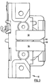
- a latch assembly illustrative of the present invention is generally indicated by reference 10 in the accompanying drawings.
- the latch assembly 10 has a housing 12 with a mouth 14 for receiving a striker 16 which is illustrated in Figures 6a through 6c.
- a ratchet 18 is mounted to the housing 12 for movement between a latched position showing in Figure 6c and an unlatched position shown in the remaining Figures. In the latched position, the ratchet 18 cooperates with the housing 12 to trap the striker 16 in the mouth 14. In the unlatched position, the striker is removable from the mouth 14.
- a ratchet spring 20 in Figure 8 may be provided to act between the ratchet 18 and housing 12 to bias the ratchet toward its unlatched position.
- a pawl 30 is mounted to the housing 12 for movement between an engaged position and a disengaged position. In the engaged position, the pawl 30 engages the ratchet 18 to hold it in its latched position to prevent withdrawal of the striker 16 from the mouth 14. In the disengaged position, the pawl allows movement of the ratchet 18 toward its unlatched position to allow withdrawal of the striker 16 from the mouth 14.
- a pawl spring 32 in Figure 7 may be provided to act between the pawl 30 and the housing 12 to urge the pawl 30 toward its engaged position.
- a release lever 40 is operably connected to the pawl 30 for moving the pawl 30 toward its disengaged position.
- latching assemblies for vehicle doors, decks, hoods, liftgates or tailgates.
- the present invention relates to apparatus associated with such latch assemblies for shielding the mouth of the latch assemblies from debris. Accordingly, it will therefore further be appreciated that such apparatus, described in detail below and referred to as a "shutter" may be adapted to a variety of typical latch assemblies.
- a shutter according to the present invention is generally indicated by reference 50.
- the shutter 50 may include a first shutter element 52 and a second shutter element 54 movable between a cover configuration covering the mouth 14 as illustrated in Figures 1, 2, 3, 4, 5, 6a and 6b and an open configuration illustrated in Figure 6c. In the open configuration, the shutter 50 allows entry of the striker 16 into the mouth 14.
- the shutter 50 is mounted to the housing 12 in a manner which allows the first and second shutter elements, 52 and 54 respectively to move in opposite relative directions.
- a representative mounting arrangement is illustrated which includes slots 60 in the housing 12 which slidably receive pins 62 extending from the first and second shutter elements, 52 and 54 respectively.
- Other arrangements may also work such as providing slots in the first and second shutter elements, 52 and 54 respectively, and corresponding pins on the housing 12.
- the first and second shutter elements, 52 and 54 respectively may be pivotably mounted to the housing 12 for a clamshell type of movement.
- the first and second shutter elements, 52 and 54 respectively may be provided with respective cam surfaces 56 and 58.
- the cam surfaces 56 and 58 cause opposite relative movement of the first and second shutter elements, 52 and 54 respectively, in response to the striker 16 being urged into the mouth 14 as shown sequentially in Figures 6a through 6c.
- Suitable biasing means such as a shutter spring 70 may be provided to urge the shutter 50 toward its cover configuration.
- the shutter spring 70 acts between the first and second shutter elements, 52 and 54, respectively.
- the shutter spring 70 also acts between the shutter 50 and the housing 12 by virtue of the constraint placed on the movement of the pins 60 in the slots 62.
- Other biasing means may be apparent to those skilled in such devices, such as having a separate spring for each shutter element mounted directly between the respective shutter element and the housing 12.
- the shutter 50 moves into its cover configuration to at least partially close the mouth and shield the latch assembly 10 from the entry of debris into the mouth 14.
Landscapes
- Lock And Its Accessories (AREA)
- Driving Mechanisms And Operating Circuits Of Arc-Extinguishing High-Tension Switches (AREA)
- Load-Engaging Elements For Cranes (AREA)
Claims (10)
- Verriegelungseinrichtung mit:einem Gehäuse mit einer Öffnung zur Aufnahme einer Schließplatte; sowieeinem Verschluss, der an dem Gehäuse montiert ist und zwischen einer Schließstellung zur Abdeckung der Öffnung und einer Offenstellung verschiebbar ist, die es der Schließplatte ermöglicht, in die Öffnung einzutreten.
- Verriegelungseinrichtung gemäß Anspruch 1, wobei:der Verschluss einen Vorspannmechanismus für den Verschluss umfasst, der mit dem Verschluss und dem Gehäuse in Wirkverbindung steht, um den Verschluss in die Schließstellung zu bringen.
- Verriegelungseinrichtung gemäß Anspruch 2, wobei:der Verschluss ein erstes und ein zweites Verschlusselement umfasst, die bei der Verschiebung von der Schließstellung in die Offenstellung voneinander weg bewegbar sind;das erste und zweite Verschlusselement Nockenoberflächen aufweisen, auf die die Schließplatte einwirkt, um den Verschluss in die Offenstellung zu verschieben; sowieder Vorspannmechanismus für den Verschluss mindestens eine, mit dem ersten und zweiten Verschlusselement verbundene Verschlussfeder aufweist, um das erste und zweite Verschlusselement in Richtung zueinander zu bewegen.
- Verriegelungseinrichtung gemäß Anspruch 3, wobei:der Vorspannmechanismus für den Verschluss eine zwischen dem Gehäuse und dem ersten und zweiten Verschlusselement wirksame Verschlussführung zur Führung der Verschiebung des ersten und zweiten Verschlusselements relativ zum Gehäuse aufweist; undder Vorspannmechanismus für den Verschluss weiterhin eine mit dem ersten und zweiten Verschlusselement verbundene Verschlussfeder aufweist.
- Verriegelungseinrichtung gemäß Anspruch 4, wobei die Verschlussführung zusammenwirkende Schlitze und Stifte in dem ersten und zweiten Verschlusselement sowie im Gehäuse zur Führung des ersten und zweiten Verschlusselements in einer Gleitbewegung relativ zum Gehäuse aufweist.
- Verriegelungseinrichtung mit:einem Gehäuse mit einer Öffnung zur Aufnahme einer Schließplatte;einem drehbar an dem Gehäuse montierten Sperrzahnrad, das mit der Öffnung zur Verschiebung zwischen einer verriegelten und einer unverriegelten Stellung zusammenwirkt;eine Sperrzahnradfeder ist zwischen dem Sperrzahnrad und dem Gehäuse montiert, um das Sperrzahnrad in Richtung auf die unverriegelte Stellung vorzuspannen;eine am Gehäuse angebrachte Sperrklinke zur Verschiebung zwischen einer eingerückten Stellung, in der das Sperrzahnrad in der verriegelten Stellung gehalten wird, um ein Herausziehen der Schließplatte zu verhindern, und einer ausgerückten Stellung, die ein Verschieben des Sperrzahnrades in Richtung auf die unverriegelte Stellung zu ermöglichen, so dass die Schließplatte aus der Öffnung herausgezogen werden kann;eine Sperrklinkenfeder wird zwischen der Sperrklinke und dem Gehäuse angebracht, um die Sperrklinke in die eingerückte Stellung zu bringen;ein mit der Sperrklinke verbundener Ausrückhebel, um die Sperrklinke-in die ausgerückte Stellung zu bringen; sowieein am Gehäuse angebrachter Verschluss, der zwischen einer geschlossenen Stellung zur Abdeckung der Öffnung und einer Offenstellung verschiebbar ist, in der die Schließplatte in die Öffnung eintreten kann.
- Eine Verriegelungseinrichtung gemäß Anspruch 6, wobei:ein Vorspannmechanismus für den Verschluss mit dem Verschluss und dem Gehäuse in Wirkverbindung steht, um den Verschluss in die Schließstellung zu bringen.
- Eine Verriegelungseinrichtung gemäß Anspruch 7, wobei:der Verschluss ein erstes und ein zweites Verschlusselement aufweist, die sich bei der Verschiebung von der geschlossenen zur offenen Stellung auseinander bewegen;das erste und das zweite Verschlusselement Nockenoberflächen aufweisen, auf die die Schließplatte zur Verschiebung des Verschlusses in die offene Stellung einwirkt, wenn die Schließplatte zur Öffnung hin bewegt wird; undder Vorspannmechanismus für den. Verschluss mindestens eine mit dem ersten und zweiten Verschlusselement verbundene Verschlussfeder aufweist, um das erste und zweite Verschlusselement in Richtung zueinander zu bewegen.
- Eine Verriegelungseinrichtung. gemäß Anspruch 8, wobei der Vorspannmechanismus für den Verschluss eine zwischen dem Gehäuse und dem ersten und zweiten Verschlusselement wirkende Verschlussführung umfasst, um die Verschiebung des ersten und zweiten Verschlusselements relativ zum Gehäuse zu führen; und
der Vorspannmechanismus für den Verschluss weiterhin eine mit dem ersten und zweiten Verschlusselement verbundene Verschlussfeder aufweist. - Eine Verriegelungseinrichtung gemäß Anspruch 9, wobei die Verschlussführung zusammenwirkende Schlitze und Stifte in dem ersten und zweiten Verschlusselement sowie in dem Gehäuse zur Führung des ersten und zweiten Verschlusselements in einer Gleitbewegung relativ zum Gehäuse aufweist.
Applications Claiming Priority (3)
| Application Number | Priority Date | Filing Date | Title |
|---|---|---|---|
| US13280199P | 1999-05-06 | 1999-05-06 | |
| US132801P | 1999-05-06 | ||
| PCT/CA2000/000503 WO2000068535A1 (en) | 1999-05-06 | 2000-05-05 | Shutter mechanism for a latch |
Publications (2)
| Publication Number | Publication Date |
|---|---|
| EP1220970A1 EP1220970A1 (de) | 2002-07-10 |
| EP1220970B1 true EP1220970B1 (de) | 2004-07-21 |
Family
ID=22455665
Family Applications (1)
| Application Number | Title | Priority Date | Filing Date |
|---|---|---|---|
| EP00924998A Expired - Lifetime EP1220970B1 (de) | 1999-05-06 | 2000-05-05 | Verschlussmechanismus für eine verriegelungsvorrichtung |
Country Status (6)
| Country | Link |
|---|---|
| EP (1) | EP1220970B1 (de) |
| AT (1) | ATE271636T1 (de) |
| AU (1) | AU4387900A (de) |
| CA (1) | CA2386620C (de) |
| DE (1) | DE60012348T2 (de) |
| WO (1) | WO2000068535A1 (de) |
Families Citing this family (3)
| Publication number | Priority date | Publication date | Assignee | Title |
|---|---|---|---|---|
| FR2927348B1 (fr) * | 2008-02-11 | 2010-04-30 | Renault Sas | Ouvrant de vehicule automobile |
| JP6442980B2 (ja) * | 2014-10-28 | 2018-12-26 | アイシン精機株式会社 | 車両用ドアロック装置 |
| US12607042B1 (en) | 2023-10-17 | 2026-04-21 | Majestic Solutions, Inc. | Lock strike shutter plate with magnetic trigger unlock mechanism |
Family Cites Families (4)
| Publication number | Priority date | Publication date | Assignee | Title |
|---|---|---|---|---|
| DE242506C (de) * | ||||
| CA1326502C (en) * | 1988-03-11 | 1994-01-25 | Wolfgang Thau | Latch mechanism, components thereof and process of manufacture for components thereof |
| DE19654380A1 (de) * | 1996-12-24 | 1998-06-25 | Mannesmann Vdo Ag | Schließeinrichtung, insbesondere für eine Heckklappe eines Kraftfahrzeuges |
| DE19732999A1 (de) * | 1997-07-31 | 1999-02-04 | Volkswagen Ag | Schließeinrichtung für eine an einem Gehäuse angelenkte Klappe, insbesondere eine Heckklappe eines Steilheck-Kraftfahrzeugs |
-
2000
- 2000-05-05 WO PCT/CA2000/000503 patent/WO2000068535A1/en not_active Ceased
- 2000-05-05 EP EP00924998A patent/EP1220970B1/de not_active Expired - Lifetime
- 2000-05-05 CA CA002386620A patent/CA2386620C/en not_active Expired - Fee Related
- 2000-05-05 AT AT00924998T patent/ATE271636T1/de not_active IP Right Cessation
- 2000-05-05 AU AU43879/00A patent/AU4387900A/en not_active Abandoned
- 2000-05-05 DE DE60012348T patent/DE60012348T2/de not_active Expired - Lifetime
Also Published As
| Publication number | Publication date |
|---|---|
| DE60012348T2 (de) | 2005-09-08 |
| ATE271636T1 (de) | 2004-08-15 |
| CA2386620C (en) | 2007-06-26 |
| WO2000068535A1 (en) | 2000-11-16 |
| DE60012348D1 (de) | 2004-08-26 |
| AU4387900A (en) | 2000-11-21 |
| EP1220970A1 (de) | 2002-07-10 |
| CA2386620A1 (en) | 2000-11-16 |
Similar Documents
| Publication | Publication Date | Title |
|---|---|---|
| US3592504A (en) | Dual-action tailgate | |
| US5853060A (en) | Automotive vehicle hood latch release system | |
| EP2940234B1 (de) | Kraftfahrzeug mit doppelter verriegelungsvorrichtung | |
| CA2507647C (en) | Lockable pet door | |
| US6009932A (en) | Push to exit, pull to enter latch assembly for screen door | |
| US5803516A (en) | Latch assembly | |
| JPH0420807B2 (de) | ||
| US5984384A (en) | Vehicle door latch device with self-cancelling mechanism | |
| US9784022B2 (en) | Latch assembly | |
| US6964440B2 (en) | Outside vehicle door handle | |
| US4597274A (en) | Lock cover mechanism | |
| US4098101A (en) | Latch mechanism for doors and the like | |
| US4612728A (en) | Double-opening device of automobile doors | |
| EP1220970B1 (de) | Verschlussmechanismus für eine verriegelungsvorrichtung | |
| CN112840093A (zh) | 车辆用车门的操作杆装置 | |
| EP1179108B1 (de) | Verschluss | |
| JP3723690B2 (ja) | コンソールボックス | |
| US2880452A (en) | Hinge mechanism | |
| CA3152439A1 (en) | Apparatus for locking a truck cover against unauthorized release | |
| US10920461B2 (en) | Vehicle door latch assemblies | |
| EP0142342A2 (de) | Schloss mit hakenförmigem Riegel | |
| JP3134063B2 (ja) | 引戸錠用係止装置 | |
| US4950006A (en) | Latch assembly for a pivotal closure member and improved latch striker means therefor | |
| JP2005016096A (ja) | ドアオートクロージャー | |
| JP4340110B2 (ja) | ドア固定装置 |
Legal Events
| Date | Code | Title | Description |
|---|---|---|---|
| PUAI | Public reference made under article 153(3) epc to a published international application that has entered the european phase |
Free format text: ORIGINAL CODE: 0009012 |
|
| 17P | Request for examination filed |
Effective date: 20020502 |
|
| AK | Designated contracting states |
Kind code of ref document: A1 Designated state(s): AT BE CH CY DE DK ES FI FR GB GR IE IT LI LU MC NL PT SE |
|
| RAP1 | Party data changed (applicant data changed or rights of an application transferred) |
Owner name: INTIER AUTOMOTIVE CLOSURES INC. |
|
| GRAP | Despatch of communication of intention to grant a patent |
Free format text: ORIGINAL CODE: EPIDOSNIGR1 |
|
| GRAS | Grant fee paid |
Free format text: ORIGINAL CODE: EPIDOSNIGR3 |
|
| GRAA | (expected) grant |
Free format text: ORIGINAL CODE: 0009210 |
|
| AK | Designated contracting states |
Kind code of ref document: B1 Designated state(s): AT BE CH CY DE DK ES FI FR GB GR IE IT LI LU MC NL PT SE |
|
| PG25 | Lapsed in a contracting state [announced via postgrant information from national office to epo] |
Ref country code: BE Free format text: LAPSE BECAUSE OF FAILURE TO SUBMIT A TRANSLATION OF THE DESCRIPTION OR TO PAY THE FEE WITHIN THE PRESCRIBED TIME-LIMIT Effective date: 20040721 Ref country code: AT Free format text: LAPSE BECAUSE OF FAILURE TO SUBMIT A TRANSLATION OF THE DESCRIPTION OR TO PAY THE FEE WITHIN THE PRESCRIBED TIME-LIMIT Effective date: 20040721 Ref country code: LI Free format text: LAPSE BECAUSE OF FAILURE TO SUBMIT A TRANSLATION OF THE DESCRIPTION OR TO PAY THE FEE WITHIN THE PRESCRIBED TIME-LIMIT Effective date: 20040721 Ref country code: NL Free format text: LAPSE BECAUSE OF FAILURE TO SUBMIT A TRANSLATION OF THE DESCRIPTION OR TO PAY THE FEE WITHIN THE PRESCRIBED TIME-LIMIT Effective date: 20040721 Ref country code: CH Free format text: LAPSE BECAUSE OF FAILURE TO SUBMIT A TRANSLATION OF THE DESCRIPTION OR TO PAY THE FEE WITHIN THE PRESCRIBED TIME-LIMIT Effective date: 20040721 Ref country code: FI Free format text: LAPSE BECAUSE OF FAILURE TO SUBMIT A TRANSLATION OF THE DESCRIPTION OR TO PAY THE FEE WITHIN THE PRESCRIBED TIME-LIMIT Effective date: 20040721 |
|
| REG | Reference to a national code |
Ref country code: GB Ref legal event code: FG4D |
|
| REG | Reference to a national code |
Ref country code: CH Ref legal event code: EP |
|
| REG | Reference to a national code |
Ref country code: IE Ref legal event code: FG4D |
|
| REF | Corresponds to: |
Ref document number: 60012348 Country of ref document: DE Date of ref document: 20040826 Kind code of ref document: P |
|
| PG25 | Lapsed in a contracting state [announced via postgrant information from national office to epo] |
Ref country code: GR Free format text: LAPSE BECAUSE OF FAILURE TO SUBMIT A TRANSLATION OF THE DESCRIPTION OR TO PAY THE FEE WITHIN THE PRESCRIBED TIME-LIMIT Effective date: 20041021 Ref country code: SE Free format text: LAPSE BECAUSE OF FAILURE TO SUBMIT A TRANSLATION OF THE DESCRIPTION OR TO PAY THE FEE WITHIN THE PRESCRIBED TIME-LIMIT Effective date: 20041021 Ref country code: DK Free format text: LAPSE BECAUSE OF FAILURE TO SUBMIT A TRANSLATION OF THE DESCRIPTION OR TO PAY THE FEE WITHIN THE PRESCRIBED TIME-LIMIT Effective date: 20041021 |
|
| PG25 | Lapsed in a contracting state [announced via postgrant information from national office to epo] |
Ref country code: ES Free format text: LAPSE BECAUSE OF FAILURE TO SUBMIT A TRANSLATION OF THE DESCRIPTION OR TO PAY THE FEE WITHIN THE PRESCRIBED TIME-LIMIT Effective date: 20041101 |
|
| NLV1 | Nl: lapsed or annulled due to failure to fulfill the requirements of art. 29p and 29m of the patents act | ||
| REG | Reference to a national code |
Ref country code: CH Ref legal event code: PL |
|
| PG25 | Lapsed in a contracting state [announced via postgrant information from national office to epo] |
Ref country code: LU Free format text: LAPSE BECAUSE OF NON-PAYMENT OF DUE FEES Effective date: 20050505 Ref country code: IE Free format text: LAPSE BECAUSE OF NON-PAYMENT OF DUE FEES Effective date: 20050505 Ref country code: CY Free format text: LAPSE BECAUSE OF FAILURE TO SUBMIT A TRANSLATION OF THE DESCRIPTION OR TO PAY THE FEE WITHIN THE PRESCRIBED TIME-LIMIT Effective date: 20050505 |
|
| ET | Fr: translation filed | ||
| PLBE | No opposition filed within time limit |
Free format text: ORIGINAL CODE: 0009261 |
|
| STAA | Information on the status of an ep patent application or granted ep patent |
Free format text: STATUS: NO OPPOSITION FILED WITHIN TIME LIMIT |
|
| PG25 | Lapsed in a contracting state [announced via postgrant information from national office to epo] |
Ref country code: MC Free format text: LAPSE BECAUSE OF NON-PAYMENT OF DUE FEES Effective date: 20050531 |
|
| 26N | No opposition filed |
Effective date: 20050422 |
|
| REG | Reference to a national code |
Ref country code: IE Ref legal event code: MM4A |
|
| PG25 | Lapsed in a contracting state [announced via postgrant information from national office to epo] |
Ref country code: PT Free format text: LAPSE BECAUSE OF NON-PAYMENT OF DUE FEES Effective date: 20041221 |
|
| REG | Reference to a national code |
Ref country code: FR Ref legal event code: PLFP Year of fee payment: 16 |
|
| PGFP | Annual fee paid to national office [announced via postgrant information from national office to epo] |
Ref country code: GB Payment date: 20150429 Year of fee payment: 16 |
|
| PGFP | Annual fee paid to national office [announced via postgrant information from national office to epo] |
Ref country code: FR Payment date: 20150508 Year of fee payment: 16 Ref country code: IT Payment date: 20150515 Year of fee payment: 16 |
|
| GBPC | Gb: european patent ceased through non-payment of renewal fee |
Effective date: 20160505 |
|
| PG25 | Lapsed in a contracting state [announced via postgrant information from national office to epo] |
Ref country code: IT Free format text: LAPSE BECAUSE OF NON-PAYMENT OF DUE FEES Effective date: 20160505 |
|
| REG | Reference to a national code |
Ref country code: FR Ref legal event code: ST Effective date: 20170131 |
|
| PG25 | Lapsed in a contracting state [announced via postgrant information from national office to epo] |
Ref country code: FR Free format text: LAPSE BECAUSE OF NON-PAYMENT OF DUE FEES Effective date: 20160531 |
|
| PG25 | Lapsed in a contracting state [announced via postgrant information from national office to epo] |
Ref country code: GB Free format text: LAPSE BECAUSE OF NON-PAYMENT OF DUE FEES Effective date: 20160505 |
|
| PGFP | Annual fee paid to national office [announced via postgrant information from national office to epo] |
Ref country code: DE Payment date: 20170502 Year of fee payment: 18 |
|
| REG | Reference to a national code |
Ref country code: DE Ref legal event code: R119 Ref document number: 60012348 Country of ref document: DE |
|
| PG25 | Lapsed in a contracting state [announced via postgrant information from national office to epo] |
Ref country code: DE Free format text: LAPSE BECAUSE OF NON-PAYMENT OF DUE FEES Effective date: 20181201 |