EP1220974B1 - Procede de forage d'un puits de forage avec des raccords amovibles - Google Patents
Procede de forage d'un puits de forage avec des raccords amovibles Download PDFInfo
- Publication number
- EP1220974B1 EP1220974B1 EP00972768A EP00972768A EP1220974B1 EP 1220974 B1 EP1220974 B1 EP 1220974B1 EP 00972768 A EP00972768 A EP 00972768A EP 00972768 A EP00972768 A EP 00972768A EP 1220974 B1 EP1220974 B1 EP 1220974B1
- Authority
- EP
- European Patent Office
- Prior art keywords
- drill string
- coupler
- disengaged
- sections
- mode
- Prior art date
- Legal status (The legal status is an assumption and is not a legal conclusion. Google has not performed a legal analysis and makes no representation as to the accuracy of the status listed.)
- Expired - Lifetime
Links
- 238000005553 drilling Methods 0.000 title claims abstract description 16
- 238000000034 method Methods 0.000 title claims abstract description 12
- 230000015572 biosynthetic process Effects 0.000 claims abstract description 9
- 239000012530 fluid Substances 0.000 claims description 27
- 230000001939 inductive effect Effects 0.000 description 4
- 239000011148 porous material Substances 0.000 description 2
- 230000003247 decreasing effect Effects 0.000 description 1
- 238000005086 pumping Methods 0.000 description 1
Images
Classifications
-
- E—FIXED CONSTRUCTIONS
- E21—EARTH OR ROCK DRILLING; MINING
- E21B—EARTH OR ROCK DRILLING; OBTAINING OIL, GAS, WATER, SOLUBLE OR MELTABLE MATERIALS OR A SLURRY OF MINERALS FROM WELLS
- E21B47/00—Survey of boreholes or wells
- E21B47/09—Locating or determining the position of objects in boreholes or wells, e.g. the position of an extending arm; Identifying the free or blocked portions of pipes
-
- E—FIXED CONSTRUCTIONS
- E21—EARTH OR ROCK DRILLING; MINING
- E21B—EARTH OR ROCK DRILLING; OBTAINING OIL, GAS, WATER, SOLUBLE OR MELTABLE MATERIALS OR A SLURRY OF MINERALS FROM WELLS
- E21B17/00—Drilling rods or pipes; Flexible drill strings; Kellies; Drill collars; Sucker rods; Cables; Casings; Tubings
- E21B17/02—Couplings; joints
- E21B17/04—Couplings; joints between rod or the like and bit or between rod and rod or the like
- E21B17/05—Swivel joints
-
- E—FIXED CONSTRUCTIONS
- E21—EARTH OR ROCK DRILLING; MINING
- E21B—EARTH OR ROCK DRILLING; OBTAINING OIL, GAS, WATER, SOLUBLE OR MELTABLE MATERIALS OR A SLURRY OF MINERALS FROM WELLS
- E21B17/00—Drilling rods or pipes; Flexible drill strings; Kellies; Drill collars; Sucker rods; Cables; Casings; Tubings
- E21B17/02—Couplings; joints
- E21B17/04—Couplings; joints between rod or the like and bit or between rod and rod or the like
- E21B17/06—Releasing-joints, e.g. safety joints
Definitions
- the present invention relates to a method of drilling a wellbore in an earth formation using a drill string connected at the upper end thereof to a rotary drive and being provided with a drill bit.
- the invention furthermore relates to a drill string for use in the method.
- a frequently encountered problem during drilling of a wellbore is sticking of the drill string in the wellbore. Such sticking can be, for example, due to differential sticking of drill string joints to the wellbore wall as a result of a pressure difference between the drilling fluid pressure in the wellbore and the pressure of earth formation fluid present in the pores of the formation. The problem is more frequently encountered in depleted oil/gas reservoirs where the pore pressure has decreased significantly.
- a drill string for drilling a wellbore in an earth formation, the drill string comprising a drill bit, means for connecting the upper end of the drill string to a rotary drive, and a plurality of couplers arranged at selected drill string intervals, each coupler interconnecting two adjacent sections of the drill string and being operable in an engaged mode in which the coupler transmits torque between the adjacent drill string sections and a disengaged mode in which the adjacent drill string sections are free to rotate relative to each other about the longitudinal axis of the drill string, each coupler being controllable by control means for moving the coupler between said engaged mode and said disengaged mode.
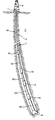
- Fig. 1 a drill string 1 extending into a wellbore 3 formed in an earth formation 5.
- the lower end of the drill string 1 is provided with a drill bit 6 and the upper end of the drill string 1 is connected to a rotary table 7 at surface for rotating the drill string, which rotary table 7 forms part of a conventional drilling rig 9.
- the drill string 1 is provided with four couplers 10, 12, 14, 16 arranged at selected intervals along the length of the drill string 1, thus dividing the drill string in drill string sections 18, 20, 22, 24, 26.
- Sections 18, 20 are interconnected by coupler 10, sections 20, 22 are interconnected by coupler 12, sections 22, 24 are interconnected by coupler 14, and sections 24, 26 are interconnected by coupler 16.
- a fluid passage (not shown) for drilling fluid extends in longitudinal direction through the drill string 1.
- Each coupler is operable in an engaged mode in which the coupler transmits rotation between the two drill string sections interconnected by the coupler, and a disengaged mode in which the couplers allows free rotation of the two drill string sections interconnected by the coupler relative to each other about the longitudinal axis of the drill string.
- coupler 10 transmits rotation from section 18 to section 20
- coupler 12 transmits rotation from section 20 to section 22
- coupler 14 transmits rotation from section 22 to section 24
- coupler 16 transmits rotation from section 24 to section 26.
- coupler 10 allows free rotation of section 18 relative to section 20
- coupler 12 allows free rotation of section 20 relative to section 22
- coupler 14 allows free rotation of section 22 relative to section
- coupler 16 allows free rotation of section 24 relative to section 26.
- Each coupler 10, 12, 14, 16 is provided with an electronic control system (not shown) for selectively switching the coupler from the engaged mode to the disengaged mode and for selectively switching the coupler from the disengaged mode to the engaged mode.
- Each control system is in communication with the fluid passage of the drill string 1 and is uniquely responsive to a selected fluid pressure variation in the fluid passage.
- the control system of coupler 10 is uniquely responsive to a first pressure variation, i.e. the other couplers are not responsive to the first pressure variation.
- the control system of coupler 12 is uniquely responsive to a second pressure variation
- the control system of coupler 14 is uniquely responsive to a third pressure variation
- the control system of coupler 16 is uniquely responsive to a fourth pressure variation.
- the first, second, third and fourth pressure variations are in the form of mutually different series of pressure pulses induced to a column of drilling fluid present in the fluid passage by a fluid pump (not shown) at the drilling rig for pumping drilling fluid through the drill string.
- each coupler 10, 12, 14, 16 is in the engaged mode.
- the fluid pump is operated to induce the first pressure variation to the column of fluid.
- the control system of coupler 10 responses so as to switch the coupler 10 to the disengaged mode, while the other couplers remain in the engaged mode.
- the rotary table 7 is then rotated, and as a result drill string section 18 is rotated due to the fact that only a limited amount of torque is needed to free drill string section 18 when compared to the torque which would be needed to free the entire drill string 1.
- the pump is operated to produce again the first pressure variation to the fluid column thereby inducing the control system of coupler 10 to switch the coupler 10 back to the engaged mode.
- the pump is operated to produce the second pressure variation in the fluid column.
- the control system of coupler 12 responses so as to switch the coupler 12 to the disengaged mode, while the other couplers remain in the engaged mode.
- the rotary table 7 is then rotated, and as a result drill string sections 18 and 20 are simultaneously rotated. It is thereby relevant to note that no differential sticking of drill string section 18 has occurred in the short period of time between engaging coupler 10 and disengaging coupler 12.
- the pump is operated to produce again the second pressure variation to the fluid column thereby inducing the control system of coupler 12 to switch the coupler 12 back to the engaged mode.
- the pump is operated to produce the third pressure variation in the fluid column.
- the control system of coupler 14 responses so as to switch the coupler 14 to the disengaged mode, while the other couplers remain in the engaged mode.
- the rotary table 7 is then rotated, and as a result drill string sections 18, 20 and 22 are simultaneously rotated. No differential sticking of drill string sections 18 and 20 has occurred in the short period of time between engaging coupler 12 and disengaging coupler 14.
- the pump is operated to produce again the third pressure variation to the fluid column thereby inducing the control system of coupler 14 to switch the coupler 14 back to the engaged mode.
- the pump is operated to produce the fourth pressure variation in the fluid column.
- the control system of coupler 16 responses so as to switch the coupler 16 to the disengaged mode, while the other couplers remain in the engaged mode.
- the rotary table 7 is then rotated, and as a result drill string sections 18, 20, 22 and 24 are simultaneously rotated. No differential sticking of drill string sections 18, 20 and 22 has occurred in the short period of time between engaging coupler 14 and disengaging coupler 16.
- the pump is operated to produce again the fourth pressure variation to the fluid column thereby inducing the control system of coupler 16 to switch the coupler 16 back to the engaged mode.
- the rotary table 7 is then rotated, and as a result the entire drill string 1 is rotated. In this manner the drill string 1 has been freed from differential sticking in a stepwise manner.
Landscapes
- Engineering & Computer Science (AREA)
- Life Sciences & Earth Sciences (AREA)
- Geology (AREA)
- Mining & Mineral Resources (AREA)
- Physics & Mathematics (AREA)
- Environmental & Geological Engineering (AREA)
- Fluid Mechanics (AREA)
- General Life Sciences & Earth Sciences (AREA)
- Geochemistry & Mineralogy (AREA)
- Mechanical Engineering (AREA)
- Geophysics (AREA)
- Earth Drilling (AREA)
Abstract
Claims (6)
- Procédé de forage d'un puits de forage dans une formation terrestre utilisant un train de tiges (1) connecté à son extrémité supérieure à un entraínement rotatif (7) et étant pourvu d'un trépan (6), le train de tiges comprenant une pluralité de raccords (10, 12, 14, 16) disposés à intervalles sélectionnés sur le train de tiges, chaque raccord interconnectant deux sections adjacentes du train de tiges et pouvant être mis en service en mode accouplé dans lequel le raccord transmet le couple entre les sections adjacentes du train de tiges et en mode désaccouplé dans lequel les sections adjacentes du train de tiges sont libres de tourner les unes par rapport aux autres autour de l'axe longitudinal du train de tiges, chaque raccord pouvant être contrôlé par des moyens de contrôle pour transférer le raccord entre ledit mode accouplé et ledit mode désaccouplé, le procédé consistant :a) à faire tourner le train de tiges de manière à forer une partie dudit puits de forage pendant que chaque raccord est dans le mode accouplé,b) quand le train de tiges est bloqué dans le puits de forage, à désaccoupler un raccord choisi parmi lesdits raccords, lequel devient de ce fait le raccord désaccouplé,c) à faire tourner la partie du train de tiges entre l'entraínement rotatif et le raccord désaccouplé,d) à accoupler le raccord désaccouplé, et à désaccoupler le raccord inférieur suivant qui devient de ce fait le raccord désaccouplé, ete) à répéter les étapes c) - d) jusqu'à ce que le raccord désaccouplé soit le raccord le plus bas.
- Procédé de la revendication 1, dans lequel à l'étape b), le train de tiges est bloqué dans le puits de forage en raison d'une adhérence différentielle.
- Train de tiges (1) pour forer un puits de forage dans une formation terrestre, le train de tiges comprenant un trépan (6), des moyens pour connecter l'extrémité supérieure du train de tiges à un entraínement rotatif (7), et caractérisé par une pluralité de raccords (10, 12, 14, 16) disposés à intervalles sélectionnés sur le train de tiges, chaque raccord interconnectant deux sections adjacentes du train de tiges et pouvant être mis en service en mode accouplé dans lequel le raccord transmet le couple entre les sections adjacentes du train de tiges et en mode désaccouplé dans lequel les sections adjacentes du train de tiges sont libres de tourner les unes par rapport aux autres autour de l'axe longitudinal du train de tiges, chaque raccord pouvant être contrôlé par des moyens de contrôle pour transférer le raccord entre ledit mode accouplé et ledit mode désaccouplé.
- Train de tiges selon la revendication 3, dans lequel le train de tiges comprend un passage fluidique pour le fluide de forage, et chaque raccord peut être contrôlé par l'action d'un changement de pression de fluide sélectionné dans le passage fluidique.
- Train de tiges selon la revendication 4, dans lequel chaque raccord peut être contrôlé par l'action d'une impulsion de pression de fluide sélectionnée dans le passage fluidique.
- Train de tiges selon la revendication 4 ou 5, dans lequel chaque raccord est pourvu d'un circuit de contrôle électronique, électrique ou électromécanique réagissant audit changement de pression de fluide sélectionné.
Priority Applications (1)
| Application Number | Priority Date | Filing Date | Title |
|---|---|---|---|
| EP00972768A EP1220974B1 (fr) | 1999-10-15 | 2000-10-13 | Procede de forage d'un puits de forage avec des raccords amovibles |
Applications Claiming Priority (4)
| Application Number | Priority Date | Filing Date | Title |
|---|---|---|---|
| EP99203404 | 1999-10-15 | ||
| EP99203404 | 1999-10-15 | ||
| EP00972768A EP1220974B1 (fr) | 1999-10-15 | 2000-10-13 | Procede de forage d'un puits de forage avec des raccords amovibles |
| PCT/EP2000/010150 WO2001029373A1 (fr) | 1999-10-15 | 2000-10-13 | Procede de forage d'un puits de forage avec des raccords amovibles |
Publications (2)
| Publication Number | Publication Date |
|---|---|
| EP1220974A1 EP1220974A1 (fr) | 2002-07-10 |
| EP1220974B1 true EP1220974B1 (fr) | 2005-12-21 |
Family
ID=8240751
Family Applications (1)
| Application Number | Title | Priority Date | Filing Date |
|---|---|---|---|
| EP00972768A Expired - Lifetime EP1220974B1 (fr) | 1999-10-15 | 2000-10-13 | Procede de forage d'un puits de forage avec des raccords amovibles |
Country Status (5)
| Country | Link |
|---|---|
| EP (1) | EP1220974B1 (fr) |
| AU (1) | AU763082B2 (fr) |
| CA (1) | CA2384811C (fr) |
| NO (1) | NO20021741D0 (fr) |
| WO (1) | WO2001029373A1 (fr) |
Families Citing this family (3)
| Publication number | Priority date | Publication date | Assignee | Title |
|---|---|---|---|---|
| GB2381806A (en) * | 2001-11-13 | 2003-05-14 | Ruff Pup Ltd | Torque isolation mechanism |
| US6858227B1 (en) | 2001-11-21 | 2005-02-22 | Sonus Pharmaceuticals, Inc. | Vitamin E conjugates |
| US7011162B2 (en) * | 2002-11-14 | 2006-03-14 | Weatherford/Lamb, Inc. | Hydraulically activated swivel for running expandable components with tailpipe |
Family Cites Families (4)
| Publication number | Priority date | Publication date | Assignee | Title |
|---|---|---|---|---|
| US3100538A (en) * | 1961-12-12 | 1963-08-13 | Houston Oil Field Mat Co Inc | Tubing rotary swivel assembly |
| CA2276517C (fr) * | 1996-12-31 | 2009-09-29 | Charles M. Helms | Dispositif de tete d'injection verrouillable et procede correspondant |
| EG21606A (en) * | 1997-02-25 | 2001-12-31 | Shell Int Research | Drill string tool |
| US5947214A (en) * | 1997-03-21 | 1999-09-07 | Baker Hughes Incorporated | BIT torque limiting device |
-
2000
- 2000-10-13 EP EP00972768A patent/EP1220974B1/fr not_active Expired - Lifetime
- 2000-10-13 CA CA002384811A patent/CA2384811C/fr not_active Expired - Fee Related
- 2000-10-13 AU AU11386/01A patent/AU763082B2/en not_active Ceased
- 2000-10-13 WO PCT/EP2000/010150 patent/WO2001029373A1/fr not_active Ceased
-
2002
- 2002-04-12 NO NO20021741A patent/NO20021741D0/no unknown
Also Published As
| Publication number | Publication date |
|---|---|
| NO20021741L (no) | 2002-04-12 |
| AU1138601A (en) | 2001-04-30 |
| CA2384811C (fr) | 2008-11-25 |
| AU763082B2 (en) | 2003-07-10 |
| WO2001029373A1 (fr) | 2001-04-26 |
| CA2384811A1 (fr) | 2001-04-26 |
| EP1220974A1 (fr) | 2002-07-10 |
| NO20021741D0 (no) | 2002-04-12 |
Similar Documents
| Publication | Publication Date | Title |
|---|---|---|
| US7131505B2 (en) | Drilling with concentric strings of casing | |
| CN101089358B (zh) | 在井底环境中便于湿或干控制线连接的方法和装置 | |
| CA2372997C (fr) | Systeme de fracturation de puits a isolation de zones multiples a manoeuvre simple | |
| US8091641B2 (en) | Method and apparatus to cement a perforated casing | |
| EP1208285B1 (fr) | Procede et dispositif permettant de deplacer des fluides de forage au moyen de fluides de completion et de fluides de reconditionnement, et de nettoyer des elements tubulaires | |
| US5671809A (en) | Method to achieve low cost zonal isolation in an open hole completion | |
| EP2212518B1 (fr) | Dispositif d'achèvement | |
| RU2642690C1 (ru) | Автономная модификация частоты вращения участка бурильной колонны | |
| EA003125B1 (ru) | Способ расширения трубчатого элемента в стволе скважины | |
| US20100032158A1 (en) | Wellbore Method and Apparatus for Completion, Production and Injection | |
| CA2614842C (fr) | Procede de fracturation d'une pluralite de laterales de sortie de tubage | |
| WO2008063072A1 (fr) | Ensemble de régulation de la pression au cours d'opérations de forage et procédé permettant de réguler la pression lors d'une opération de forage dans une formation possédant une pression de formation élevée non prévisible | |
| WO2008064233A2 (fr) | Ensemble de perforateur avec tarière pour contrôler la dynamique des fluides de puits de forage | |
| WO1997043514A1 (fr) | Systeme d'entrainement en sections | |
| NO349432B1 (en) | Method and system for abandoning a cased borehole | |
| CA2384811C (fr) | Procede de forage d'un puits de forage avec des raccords amovibles | |
| US4113236A (en) | Pulling tool apparatus | |
| GB2237594A (en) | Dislodging sand bridges | |
| EP3717739B1 (fr) | Procédé et appareil de lavage de complétion supérieure | |
| US11047196B2 (en) | Production tubing conversion device and methods of use | |
| Nowak et al. | Rigless multizone recompletion using a cement packer placed with coiled tubing: A case history | |
| CA2585476C (fr) | Forage a colonnes de tubage concentriques | |
| CN117662006A (zh) | 一种找回老井眼的方法 | |
| WO2007050530A1 (fr) | Procede de fracturation d’une pluralite de laterales de sortie de tubage | |
| MXPA00002095A (en) | Assembly and process for drilling and completing multiple wells |
Legal Events
| Date | Code | Title | Description |
|---|---|---|---|
| PUAI | Public reference made under article 153(3) epc to a published international application that has entered the european phase |
Free format text: ORIGINAL CODE: 0009012 |
|
| 17P | Request for examination filed |
Effective date: 20020304 |
|
| AK | Designated contracting states |
Kind code of ref document: A1 Designated state(s): AT BE CH CY DE DK ES FI FR GB GR IE IT LI LU MC NL PT SE |
|
| AX | Request for extension of the european patent |
Free format text: AL;LT;LV;MK;RO;SI |
|
| RBV | Designated contracting states (corrected) |
Designated state(s): GB NL |
|
| REG | Reference to a national code |
Ref country code: DE Ref legal event code: 8566 |
|
| GRAP | Despatch of communication of intention to grant a patent |
Free format text: ORIGINAL CODE: EPIDOSNIGR1 |
|
| GRAS | Grant fee paid |
Free format text: ORIGINAL CODE: EPIDOSNIGR3 |
|
| GRAA | (expected) grant |
Free format text: ORIGINAL CODE: 0009210 |
|
| AK | Designated contracting states |
Kind code of ref document: B1 Designated state(s): GB NL |
|
| REG | Reference to a national code |
Ref country code: GB Ref legal event code: FG4D |
|
| PLBE | No opposition filed within time limit |
Free format text: ORIGINAL CODE: 0009261 |
|
| STAA | Information on the status of an ep patent application or granted ep patent |
Free format text: STATUS: NO OPPOSITION FILED WITHIN TIME LIMIT |
|
| 26N | No opposition filed |
Effective date: 20060922 |
|
| PGFP | Annual fee paid to national office [announced via postgrant information from national office to epo] |
Ref country code: NL Payment date: 20081021 Year of fee payment: 9 |
|
| REG | Reference to a national code |
Ref country code: NL Ref legal event code: V1 Effective date: 20100501 |
|
| PG25 | Lapsed in a contracting state [announced via postgrant information from national office to epo] |
Ref country code: NL Free format text: LAPSE BECAUSE OF NON-PAYMENT OF DUE FEES Effective date: 20100501 |
|
| PGFP | Annual fee paid to national office [announced via postgrant information from national office to epo] |
Ref country code: GB Payment date: 20181010 Year of fee payment: 19 |
|
| GBPC | Gb: european patent ceased through non-payment of renewal fee |
Effective date: 20191013 |
|
| PG25 | Lapsed in a contracting state [announced via postgrant information from national office to epo] |
Ref country code: GB Free format text: LAPSE BECAUSE OF NON-PAYMENT OF DUE FEES Effective date: 20191013 |