EP1220979B1 - Verfahren zum regeln von drehmomentänderungen in brennkraftmaschinen und brennkraftmaschine mit entsprechender regelung - Google Patents
Verfahren zum regeln von drehmomentänderungen in brennkraftmaschinen und brennkraftmaschine mit entsprechender regelung Download PDFInfo
- Publication number
- EP1220979B1 EP1220979B1 EP00971957A EP00971957A EP1220979B1 EP 1220979 B1 EP1220979 B1 EP 1220979B1 EP 00971957 A EP00971957 A EP 00971957A EP 00971957 A EP00971957 A EP 00971957A EP 1220979 B1 EP1220979 B1 EP 1220979B1
- Authority
- EP
- European Patent Office
- Prior art keywords
- torque
- engine
- control unit
- fuel
- accelerator pedal
- Prior art date
- Legal status (The legal status is an assumption and is not a legal conclusion. Google has not performed a legal analysis and makes no representation as to the accuracy of the status listed.)
- Expired - Lifetime
Links
- 238000002485 combustion reaction Methods 0.000 title claims abstract description 16
- 238000000034 method Methods 0.000 title claims abstract description 12
- 239000000446 fuel Substances 0.000 claims abstract description 31
- 230000001133 acceleration Effects 0.000 claims description 10
- 230000008859 change Effects 0.000 claims description 8
- 230000006835 compression Effects 0.000 claims description 5
- 238000007906 compression Methods 0.000 claims description 5
- 230000001419 dependent effect Effects 0.000 claims description 4
- 230000007423 decrease Effects 0.000 claims description 3
- 230000009467 reduction Effects 0.000 claims description 3
- 230000009849 deactivation Effects 0.000 claims description 2
- 238000002347 injection Methods 0.000 abstract description 7
- 239000007924 injection Substances 0.000 abstract description 7
- 230000000994 depressogenic effect Effects 0.000 abstract 1
- 238000010586 diagram Methods 0.000 description 5
- 239000000725 suspension Substances 0.000 description 5
- 239000000779 smoke Substances 0.000 description 3
- 239000003112 inhibitor Substances 0.000 description 2
- 230000005540 biological transmission Effects 0.000 description 1
- 230000000694 effects Effects 0.000 description 1
- 230000003993 interaction Effects 0.000 description 1
- 230000035939 shock Effects 0.000 description 1
- 230000007704 transition Effects 0.000 description 1
Images

Classifications
-
- F—MECHANICAL ENGINEERING; LIGHTING; HEATING; WEAPONS; BLASTING
- F02—COMBUSTION ENGINES; HOT-GAS OR COMBUSTION-PRODUCT ENGINE PLANTS
- F02D—CONTROLLING COMBUSTION ENGINES
- F02D11/00—Arrangements for, or adaptations to, non-automatic engine control initiation means, e.g. operator initiated
- F02D11/06—Arrangements for, or adaptations to, non-automatic engine control initiation means, e.g. operator initiated characterised by non-mechanical control linkages, e.g. fluid control linkages or by control linkages with power drive or assistance
- F02D11/10—Arrangements for, or adaptations to, non-automatic engine control initiation means, e.g. operator initiated characterised by non-mechanical control linkages, e.g. fluid control linkages or by control linkages with power drive or assistance of the electric type
- F02D11/105—Arrangements for, or adaptations to, non-automatic engine control initiation means, e.g. operator initiated characterised by non-mechanical control linkages, e.g. fluid control linkages or by control linkages with power drive or assistance of the electric type characterised by the function converting demand to actuation, e.g. a map indicating relations between an accelerator pedal position and throttle valve opening or target engine torque
-
- F—MECHANICAL ENGINEERING; LIGHTING; HEATING; WEAPONS; BLASTING
- F02—COMBUSTION ENGINES; HOT-GAS OR COMBUSTION-PRODUCT ENGINE PLANTS
- F02D—CONTROLLING COMBUSTION ENGINES
- F02D41/00—Electrical control of supply of combustible mixture or its constituents
- F02D41/30—Controlling fuel injection
- F02D41/38—Controlling fuel injection of the high pressure type
-
- B—PERFORMING OPERATIONS; TRANSPORTING
- B60—VEHICLES IN GENERAL
- B60W—CONJOINT CONTROL OF VEHICLE SUB-UNITS OF DIFFERENT TYPE OR DIFFERENT FUNCTION; CONTROL SYSTEMS SPECIALLY ADAPTED FOR HYBRID VEHICLES; ROAD VEHICLE DRIVE CONTROL SYSTEMS FOR PURPOSES NOT RELATED TO THE CONTROL OF A PARTICULAR SUB-UNIT
- B60W2510/00—Input parameters relating to a particular sub-units
- B60W2510/06—Combustion engines, Gas turbines
- B60W2510/0638—Engine speed
- B60W2510/0652—Speed change rate
-
- F—MECHANICAL ENGINEERING; LIGHTING; HEATING; WEAPONS; BLASTING
- F02—COMBUSTION ENGINES; HOT-GAS OR COMBUSTION-PRODUCT ENGINE PLANTS
- F02D—CONTROLLING COMBUSTION ENGINES
- F02D2250/00—Engine control related to specific problems or objectives
- F02D2250/18—Control of the engine output torque
- F02D2250/21—Control of the engine output torque during a transition between engine operation modes or states
Definitions
- the present invention relates to a method of controlling changes in torque in an internal combustion engine having a control unit, which controls the amount of fuel to the engine combustion chambers dependent on signals fed into the control unit which represent at least the accelerator pedal position and engine speed.
- the invention also relates to an internal combustion engine for motor vehicles with an injector for each cylinder and an electronic control unit, controlling the amount of fuel which is injected into the combustion chamber of the respective cylinder, dependent on signals, fed into the control unit, representing at least accelerator position and engine speed.
- the fuel injection in vehicle engines with unit injectors can be controlled very carefully and rapidly, which means that the torque from the engine can change quite rapidly. At times this can result in problems for certain parts of the vehicle drive train, i.e. the gearbox, the rear axle and the wheel suspension, which do not handle satisfactorily torque transmission during the rapid torque transients which can occur.
- the problems manifest themselves in the form of banging and knocking in the gearbox, rear axle and/or the wheel suspension.
- the rapid torque increases and decreases, which can occur in engines with unit injectors can also cause such heavy impacts in the drive train that certain types of rear axles and wheel suspensions cannot, in practice, be used unless the changes in torque can be effected in a controlled manner so that the torque transients are dampened.
- One purpose of the present invention is to achieve a method of controlling, in an internal combustion engine, torque changes initiated by changes in the accelerator position so that the torque change is effected smoothly and passes the zero torque level in a controlled manner, i.e. the transition from braking to pulling torque or vice versa, to give the rest of the drive train time to take up the gap and eliminate or reduce the twisting up of various chassis components.
- JP2023240 A discloses a usual fuel injection control, wherein the fuel is controlled (cut /no -cut) according to the accelerator idle position.
- the fuel amount is controlled -in a first step to a first amount- not corresponding to the final amount- but to an intermediate amount (not corresponding to the requested torque) and than the fuel is gradually controlled to the level of the requested torque.
- An internal combustion engine of the type described by way of introduction is characterized according to the invention in that in the control unit there are stored values of the frictional torque of the engine as a function of engine speed, and values of first and second upper and lower torque limits related to the frictional torque, and that the control unit is arranged, when the accelerator pedal position is changed from a position representing a current engine torque to a new position representing a requested engine torque lying, for opening throttle, above said first upper torque limit or, for closing throttle, below said second lower torque limit, to control the amount of fuel so that an engine torque different from the requested torque is first achieved and that, during a predetermined time interval, the amount of fuel is thereafter controlled towards a level corresponding to the requested or to the maximum permissible torque.
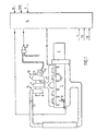
- Fig. 1 shows a schematic presentation of an internal combustion engine according to the invention
- Fig. 2 shows a diagram of the torque control during throttle opening (torque) increase
- Fig. 3 is a corresponding diagram of torque control during throttle opening (torque) decrease.
- Fig. 1 shows schematically a turbo-charged six-cylinder four-stroke engine 1 with a gearbox 2 connected thereto.
- a turbocompressor generally designated 3
- the engine 1 has a schematically indicated compression braking device 8 of a type known per se, by means of which the cylinders of the engine, during the latter portion of the intake stroke as well as during the latter portion of the compression stroke, can be connected to the engine exhaust manifold 5 to increase the engine braking effect.
- the outlet 9 of the turbine 4 opens into an exhaust pressure regulator, generally designated 10, which can be of a type known per se, and it comprises a wastegate housing 11 containing a wastegate (not shown) and a pneumatic control means 12 joined to the wastegate and which communicates via a control valve 13 with a source of compressed air, e.g. the compressed air tank of the vehicle brake system.
- a source of compressed air e.g. the compressed air tank of the vehicle brake system.
- An electronic control unit 14 comprising a computer has a number of control functions which are determined by signals, fed into the control unit from various sensors, representing various engine data, such as engine r.p.m., charge pressure (degree of charging) (p) and air temperature (t) as well as vehicle data, such as engine speed (s), accelerator pedal position (tp) and clutch pedal position (cp).
- engine data such as engine r.p.m., charge pressure (degree of charging) (p) and air temperature (t) as well as vehicle data, such as engine speed (s), accelerator pedal position (tp) and clutch pedal position (cp).
- Fig. 1 there is indicated schematically the control of the amount of injected fuel through the engine fuel injectors 15, which can be so-called unit injectors with integrated fuel pump means, and control of the switching on-and-off of the compression braking device 8 and the setting of the exhaust pressure regulator 10 wastegate.
- first upper torque limit "b” which, for the given engine, can lie ca 360 Nm above the friction torque
- first lower torque limit "c” which, for the given engine, can lie ca 200 Nm above the friction torque
- second upper torque limit "d” which can lie ca 130 Nm above the friction torque
- a second lower torque limit "e” which can lie ca 50 Nm below the friction torque
- Fig. 2 there is illustrated how the control unit 14 controls the fuel injection for torque change at throttle opening (torque) increase from braking (dragging) torque to a desired driving torque, which is indicated by the dashed line “tq".
- the requested torque here lies above the first upper torque limit "b", which means that the torque is first allowed to increase along the ramp A to the first lower torque limit "c” and is thereafter limited along the ramp B during a time period of ca 0.1 seconds, as is indicated by the arrows "f” in Fig. 2, until the torque limit "b" has been reached.
- the torque is then released up along the ramp C until the requested torque, represented by the accelerator pedal position, is reached.
- Two different ramps B for increasing torque are programmed into the control unit 14, the first, as shown in Fig. 2, applicable to normal opening of the throttle, i.e. without previous deactivation of activated engine braking devices 8, 10, and secondly a ramp approximately twice the length, i.e. ca 0.2 seconds, and employed for acceleration after the engine braking devices have been activated, so that these devices are given time to let go before too much fuel is injected.
- the longer ramp for torque increase is primarily optimized to counter smoke generation, which will be the result of fuel injection with the engine brake still activated.
- Fig. 3 illustrates in a corresponding manner how the control unit 14 controls the fuel injection when the accelerator pedal is let up to change torque from driving torque to braking (dragging) torque, which lies below the second torque limit "e".
- the driver for example from full throttle, lets up the accelerator pedal rapidly, the torque will follow the curve GHIJ. Since the torque, requested by the driver, can however be greater than that given (limited by full load or smoke inhibitors), the torque is guided directly to the current torque, as illustrated by the ramp G. This is done, on the one hand, so that the ramp times do not need to be adapted to different power variants, but primarily due to the fact that the torque limitation of the smoke inhibitor has a slow operation, and it can at times be a great difference between the requested torque and the permitted torque.
- the ramp H is activated, as shown in Fig. 3, when the requested torque is less than the permitted, and it is activated for ca 0.15 seconds, if one starts from maximum torque.
- the ramp I is activated for ca 0.15 seconds to dampen the passage through the zero-torque line.
- the torque is allowed to drop along the ramp J to zero.
- the function described provides the greatest usefulness in the lower gear speeds with high torque on the gearbox output shaft when the frame, the propeller shaft, the driving axles and the suspension are tightened up. If the torque is reduced too rapidly, the engine will quickly begin to drag (brake) and all of the play in the drive train will be used when the engine goes over to negative torque. When the frame, the axles and the suspension then strive to spring back, there is no slack in the drive train, and therefore these mass forces will act rigidly against the engine causing banging and knocking in the chassis.
- the ramp I is therefore optimized to minimize the knocking which normally occurs when the zero-torque line is passed.
- the ramps GHIJ are activated and the torque is let down along the curve "tq".
- the acceleration limit is speed-dependent so that the gradual torque reduction will not always be disengaged when in low gears, where engine acceleration is high compared to high gears.
- This function means that the ramps can be optimized without regard to the shifting sequence, i.e. the ramps can be made long without this affecting the interaction between the clutch and the gas pedal when shifting. Since there is no need for a delay of the torque change when the clutch is disengaged, there is also a sensor which directly senses the position of the clutch pedal and provides a signal to the control unit to deactivate the ramps when the clutch is disengaged.
Landscapes
- Engineering & Computer Science (AREA)
- Chemical & Material Sciences (AREA)
- Combustion & Propulsion (AREA)
- Mechanical Engineering (AREA)
- General Engineering & Computer Science (AREA)
- Electrical Control Of Air Or Fuel Supplied To Internal-Combustion Engine (AREA)
Claims (10)
- Verfahren zum Steuern von Drehmomentveränderungen in einem Verbrennungsmotor mit einer Steuereinheit, welche die Kraftstoffmenge zu den Motorbrennkammern in Abhängigkeit von in die Steuereinheit zugeführten Signalen steuert, welche zumindest die Gaspedalposition und die Motordrehzahl darstellen, wobei die Kraftstoffmenge durch die Steuereinheit (14) derart gesteuert wird, dass eine Veränderung der Gaspedalposition von einer Position, die ein gegenwärtiges Motordrehmoment darstellt, in eine neue Position, die ein gefordertes Motordrehmoment darstellt, und die ein Umschalten von einem Brems- zu einem Antriebsdrehmoment oder umgekehrt von einem Antriebs- zu einem Bremsdrehmoment mit sich bringt, dazu führt, dass Signale von der Steuereinheit die Kraftstoffmenge derart steuern, dass ein Niveau des Motordrehmoments (c, d), das sich von dem geforderten Drehmomentniveau (tq) unterscheidet, zuerst erzielt wird, und dass während eines vorbestimmten Zeitintervalls (t) die Kraftstoffmenge danach graduell zu einem Drehmomentniveau entsprechend dem geforderten oder maximal zulässigen Drehmomentniveau gesteuert wird, dadurch gekennzeichnet, dass das Drehmomentniveau (c, d), das sich von dem geforderten Drehmomentniveau unterscheidet, basierend auf der Größenordnung des Reibungsdrehmoments (a) des Motors bei verschiedenen Motordrehzahlen ausgewählt wird.
- Verfahren nach Anspruch 1, dadurch gekennzeichnet, dass die Menge des Kraftstoffs auf solche Weise gesteuert wird, um, wenn die Gaspedalposition verändert wird, einen Drehmomentanstieg von einem Brems- zu einem Antriebsdrehmoment zu bewirken, das oberhalb einer ersten vorbestimmten oberen Drehmomentgrenze (b) liegt, dass das Drehmoment zuerst auf eine erste vorbestimmte untere Drehmomentgrenze (c) begrenzt wird, dass das Drehmoment danach während eines vorbestimmten Zeitintervalls (t) graduell zu der ersten vorbestimmten oberen Drehmomentgrenze (b) gesteuert wird und dass das Drehmoment, wenn die erste vorbestimmte obere Drehmomentgrenze erreicht worden ist, zu dem Drehmoment (tq) freigegeben wird, das durch die Gaspedalposition dargestellt ist.
- Verfahren nach Anspruch 1, dadurch gekennzeichnet, dass die Kraftstoffmenge derart bei einer Veränderung der Gaspedalposition gesteuert wird, um eine Verminderung des Drehmoments von einem Antriebs- zu einem Bremsdrehmoment zu bewirken, das unterhalb einer zweiten vorbestimmten unteren Drehmomentgrenze (e) liegt, dass das Drehmoment zuerst während eines vorbestimmten ersten Zeitintervalls graduell nach unten von dem gegenwärtigen Drehmoment (tq) zu einer zweiten vorbestimmten oberen Drehmomentgrenze (d) gesteuert wird, und dass das Drehmoment danach von der zweiten vorbestimmten oberen Drehmomentgrenze während eines zweiten vorbestimmten Zeitintervalls graduell nach unten zu der zweiten vorbestimmten unteren Drehmomentgrenze (e) gesteuert wird, und dass das Drehmoment, wenn das zweite vorbestimmte untere Drehmoment erreicht worden ist, nach unten zu dem Drehmoment freigegeben wird, das durch die Gaspedalposition dargestellt ist.
- Verfahren nach Anspruch 2 oder 3, dadurch gekennzeichnet, dass die Drehmomentgrenzen derart ausgewählt sind, dass die erste obere und untere Drehmomentgrenze (b, c) und die zweite obere Drehmomentgrenze (d) oberhalb des Reibungsdrehmoments des Motors liegen, während die zweite untere Drehmomentgrenze (e) unterhalb des Reibungsdrehmoments des Motors liegt.
- Verfahren nach einem der Ansprüche 1 - 4, dadurch gekennzeichnet, dass die Position einer Reibungskupplung, die zwischen dem Motor und einem Getriebe angeordnet ist, direkt oder indirekt erfasst wird, und dass bei einer Veränderung der Gaspedalposition bei gelöster Kupplung die Kraftstoffmenge ohne Verzögerung auf ein Niveau entsprechend dem geforderten oder maximal zulässigen Drehmoment gesteuert wird.
- Verfahren nach einem der Ansprüche 2 - 5 beim Steuern von Drehmomentveränderungen in einem Dieselmotor mit Kompressions- und/oder Abgasbremsen, dadurch gekennzeichnet, dass das Zeitintervall (t), während dessen das Drehmoment graduell von der ersten unteren Drehmomentgrenze (c) zu der ersten oberen Drehmomentgrenze (b) gesteuert wird, länger ist für einen Drehmomentanstieg, der einer Deaktivierung einer aktivierten Kompressions- und/oder Abgasbremse folgt, als sonst.
- Verfahren nach einem der Ansprüche 1 - 6, dadurch gekennzeichnet, dass die Beschleunigung der Motordrehzahl gemessen wird, und dass die Kraftstoffmenge derart gesteuert wird, dass das Drehmoment, wenn das Gaspedal losgelassen wird, auf das durch die Gaspedalposition geforderte Niveau oder das zulässige Niveau fallen wird, falls die Beschleunigung ein vorbestimmtes Niveau überschreitet, das in der Steuereinheit gespeichert ist.
- Verbrennungsmotor für Motorfahrzeuge mit einem Injektor für jeden Zylinder und einer elektronischen Steuereinheit, die die Kraftstoffmenge steuert, welche in die Brennkammer jedes der jeweiligen Zylinder eingespritzt wird, in Abhängigkeit von in die Steuereinheit zugeführten Signalen, welche zumindest die Gaspedalposition und die Motordrehzahl darstellen, dadurch gekennzeichnet, dass in der Steuereinheit (14) Werte des Reibungsdrehmoments (a) des Motors als eine Funktion der Motordrehzahl und Werte einer ersten und einer zweiten, oberen und unteren Drehmomentgrenze (b, c, d, e), die sich auf das Reibungsdrehmoment beziehen, gespeichert sind, und dass die Steuereinheit angeordnet ist, wenn die Gaspedalposition von einer Position, welche ein gegenwärtiges Motordrehmoment darstellt, in eine neue Position, die ein gefordertes Motordrehmoment (tq) darstellt, das für einen Anstieg der Drosselöffnung oberhalb der ersten oberen Drehmomentgrenze (b) oder für eine Abnahme der Drosselöffnung unterhalb der zweiten unteren Drehmomentgrenze (c) liegt, um die Kraftstoffmenge derart zu steuern, dass ein Motordrehmoment (c, d), das von dem geforderten Drehmoment unterschiedlich ist, zuerst erzielt wird, und dass während eines vorbestimmten Zeitintervalls die Kraftstoffmenge danach zu einem Niveau gesteuert wird, welches dem geforderten oder dem maximal zulässigen Drehmoment entspricht.
- Verbrennungsmotor nach Anspruch 8, dadurch gekennzeichnet, dass in der Steuereinheit (14) Werte der ersten oberen (b) und unteren (c) Drehmomentgrenze und der zweiten unteren Drehmomentgrenze (d), die oberhalb des Reibungsdrehmoments (a) des Motors liegen, und Werte der zweiten unteren Drehmomentgrenze (e), die unterhalb des Reibungsdrehmoments des Motors liegen, gespeichert sind.
- Verbrennungsmotor nach Anspruch 8 oder 9, dadurch gekennzeichnet, dass die Steuereinheit (14) angeordnet ist, um die Beschleunigung der Motordrehzahl zu messen, und um, wenn es einen Drehmomentanstieg gibt, der zu einer Beschleunigung führt, welche ein vorbestimmtes Niveau überschreitet, die Kraftstoffmenge ohne Verzögerung auf ein Niveau zu steuern, welches dem geforderten Drehmoment (tq) oder dem maximal zulässigen Drehmoment entspricht.
Applications Claiming Priority (3)
| Application Number | Priority Date | Filing Date | Title |
|---|---|---|---|
| US09/418,757 US6220226B1 (en) | 1999-10-15 | 1999-10-15 | Method of controlling changes in torque in an internal combustion engine and an internal combustion engine controlled in accordance with said method |
| US418757 | 1999-10-15 | ||
| PCT/SE2000/001988 WO2001027453A1 (en) | 1999-10-15 | 2000-10-13 | Method of controlling changes in torque in an internal combustion engine and an internal combustion engine controlled in accordance with said method |
Publications (2)
| Publication Number | Publication Date |
|---|---|
| EP1220979A1 EP1220979A1 (de) | 2002-07-10 |
| EP1220979B1 true EP1220979B1 (de) | 2005-12-14 |
Family
ID=23659458
Family Applications (1)
| Application Number | Title | Priority Date | Filing Date |
|---|---|---|---|
| EP00971957A Expired - Lifetime EP1220979B1 (de) | 1999-10-15 | 2000-10-13 | Verfahren zum regeln von drehmomentänderungen in brennkraftmaschinen und brennkraftmaschine mit entsprechender regelung |
Country Status (4)
| Country | Link |
|---|---|
| US (1) | US6220226B1 (de) |
| EP (1) | EP1220979B1 (de) |
| DE (1) | DE60024852T2 (de) |
| WO (1) | WO2001027453A1 (de) |
Families Citing this family (11)
| Publication number | Priority date | Publication date | Assignee | Title |
|---|---|---|---|---|
| DE10036282A1 (de) * | 2000-07-26 | 2002-02-07 | Bosch Gmbh Robert | Verfahren und Vorrichtung zur Steuerung einer Antriebseinheit |
| US6620077B2 (en) * | 2001-09-04 | 2003-09-16 | Caterpillar Inc | Work machine having a drive train with an enhanced braking mode |
| US20030082632A1 (en) * | 2001-10-25 | 2003-05-01 | Cytoprint, Inc. | Assay method and apparatus |
| SE526431C2 (sv) * | 2004-01-15 | 2005-09-13 | Kone Cargotec Patenter Hb | Truck innefattande ett hastighetsreglerande system |
| SE526382C2 (sv) * | 2004-01-16 | 2005-09-06 | Scania Cv Abp | Anordning samt förfarande för dämpning |
| JP2006307797A (ja) * | 2005-05-02 | 2006-11-09 | Yamaha Motor Co Ltd | 鞍乗型車両のエンジン制御装置及びエンジン制御方法 |
| DE102006020062A1 (de) * | 2006-04-29 | 2007-10-31 | Dr.Ing.H.C. F. Porsche Ag | Verfahren zur Steuerung einer Brennkraftmaschine |
| JP4887204B2 (ja) * | 2007-04-23 | 2012-02-29 | ボッシュ株式会社 | 全閉位置学習方法及び車両動作制御装置 |
| SE538535C2 (sv) * | 2012-03-27 | 2016-09-13 | Scania Cv Ab | Anordning och förfarande för begränsning av momentuppbyggnadhos en motor hos ett motorfordon |
| WO2016194068A1 (ja) * | 2015-05-29 | 2016-12-08 | 日産自動車株式会社 | 車両用内燃機関の制御装置 |
| US11560133B2 (en) * | 2020-09-29 | 2023-01-24 | GM Global Technology Operations LLC | Systems and methods for limiting engine torque and controlling a clutch |
Citations (1)
| Publication number | Priority date | Publication date | Assignee | Title |
|---|---|---|---|---|
| JPH0223240A (ja) * | 1988-07-12 | 1990-01-25 | Mazda Motor Corp | エンジンの燃料制御装置 |
Family Cites Families (11)
| Publication number | Priority date | Publication date | Assignee | Title |
|---|---|---|---|---|
| JPS5934428A (ja) * | 1982-08-20 | 1984-02-24 | Honda Motor Co Ltd | 内燃エンジンの燃料供給制御方法 |
| DE3924077A1 (de) * | 1989-07-20 | 1991-01-24 | Bosch Gmbh Robert | Verfahren zur steuerung der kraftstoffmenge von brennkraftmaschinen |
| US5163530A (en) * | 1989-12-11 | 1992-11-17 | Nissan Motor Company, Limited | Control system for controlling driving torque delivered for driven wheels |
| US5225892A (en) * | 1990-02-05 | 1993-07-06 | Canon Kabushiki Kaisha | Positional deviation detecting method |
| JPH04203250A (ja) * | 1990-11-29 | 1992-07-23 | Mitsubishi Motors Corp | 走行負荷分補償式速度制御部付ドライブバイワイヤ式車両 |
| US5213178A (en) * | 1992-04-21 | 1993-05-25 | General Motors Corporation | Traction control system with fuel and spark control |
| US5479898A (en) * | 1994-07-05 | 1996-01-02 | Ford Motor Company | Method and apparatus for controlling engine torque |
| JPH1047115A (ja) * | 1996-08-07 | 1998-02-17 | Denso Corp | 電子スロットル制御装置 |
| SE522177C2 (sv) * | 1996-08-27 | 2004-01-20 | Mitsubishi Motors Corp | Styranordning för en förbränningsmotor med cylinderinsprutning och gnisttändning |
| US6061623A (en) * | 1998-07-17 | 2000-05-09 | Ford Global Technologies, Inc. | Method and system for pre-positioning wheel torque in a torque based vehicle speed control |
| US6119063A (en) * | 1999-05-10 | 2000-09-12 | Ford Global Technologies, Inc. | System and method for smooth transitions between engine mode controllers |
-
1999
- 1999-10-15 US US09/418,757 patent/US6220226B1/en not_active Expired - Lifetime
-
2000
- 2000-10-13 WO PCT/SE2000/001988 patent/WO2001027453A1/en not_active Ceased
- 2000-10-13 EP EP00971957A patent/EP1220979B1/de not_active Expired - Lifetime
- 2000-10-13 DE DE60024852T patent/DE60024852T2/de not_active Expired - Lifetime
Patent Citations (1)
| Publication number | Priority date | Publication date | Assignee | Title |
|---|---|---|---|---|
| JPH0223240A (ja) * | 1988-07-12 | 1990-01-25 | Mazda Motor Corp | エンジンの燃料制御装置 |
Also Published As
| Publication number | Publication date |
|---|---|
| WO2001027453A1 (en) | 2001-04-19 |
| EP1220979A1 (de) | 2002-07-10 |
| DE60024852D1 (de) | 2006-01-19 |
| US6220226B1 (en) | 2001-04-24 |
| DE60024852T2 (de) | 2006-06-22 |
Similar Documents
| Publication | Publication Date | Title |
|---|---|---|
| AU716458B2 (en) | Fixed throttle torque demand strategy | |
| US6615584B2 (en) | Method for controlling the boost pressure on a piston internal combustion engine with a turbocharger | |
| US5101786A (en) | Control system for controlling output torque of internal combustion engine | |
| US5819538A (en) | Turbocharged engine system with recirculation and supplemental air supply | |
| US4924832A (en) | System and method for controlling ignition timing for internal combustion engine | |
| US5819705A (en) | Process and system for controlling a motor vehicle diesel engine | |
| JP2843115B2 (ja) | エンジン出力制御を含めた流体継手の締結力制御装置 | |
| JPS6347891B2 (de) | ||
| EP1220979B1 (de) | Verfahren zum regeln von drehmomentänderungen in brennkraftmaschinen und brennkraftmaschine mit entsprechender regelung | |
| JPS6123377B2 (de) | ||
| US5460580A (en) | Method and arrangement for controlling the drive power of a drive unit of a motor vehicle | |
| JPWO1992017347A1 (ja) | 内燃機関と連続可変変速機との制御装置 | |
| US20080060614A1 (en) | Throttle opening control system and method for internal combustion engine | |
| JPH0340232B2 (de) | ||
| US4612827A (en) | Accelerator control for a vehicular propulsion system having a continuously variable ratio transmission | |
| US5551932A (en) | Engine idle control during braking with lockup clutch being released | |
| JP2920710B2 (ja) | 車両のクリープ制御装置 | |
| JP3438642B2 (ja) | 車両の制御装置 | |
| US20220281433A1 (en) | Control device for vehicle | |
| JP3167352B2 (ja) | エンジンの失火検出装置 | |
| JP2560501B2 (ja) | 車両用排気ターボチャージャ付エンジンの過給圧制御装置 | |
| JP2862643B2 (ja) | 自動変速機及びエンジンの制御装置 | |
| JPH03153426A (ja) | 車両のエンジン出力制御方法 | |
| JP2900287B2 (ja) | 油圧式クラッチの制御装置 | |
| EP0120460B1 (de) | Kraftfahrzeug-Antriebssteuerung |
Legal Events
| Date | Code | Title | Description |
|---|---|---|---|
| PUAI | Public reference made under article 153(3) epc to a published international application that has entered the european phase |
Free format text: ORIGINAL CODE: 0009012 |
|
| 17P | Request for examination filed |
Effective date: 20020430 |
|
| AK | Designated contracting states |
Kind code of ref document: A1 Designated state(s): AT BE CH CY DE DK ES FI FR GB GR IE IT LI LU MC NL PT SE |
|
| RBV | Designated contracting states (corrected) |
Designated state(s): DE FR SE |
|
| 17Q | First examination report despatched |
Effective date: 20041105 |
|
| GRAP | Despatch of communication of intention to grant a patent |
Free format text: ORIGINAL CODE: EPIDOSNIGR1 |
|
| GRAS | Grant fee paid |
Free format text: ORIGINAL CODE: EPIDOSNIGR3 |
|
| GRAA | (expected) grant |
Free format text: ORIGINAL CODE: 0009210 |
|
| AK | Designated contracting states |
Kind code of ref document: B1 Designated state(s): DE FR SE |
|
| REF | Corresponds to: |
Ref document number: 60024852 Country of ref document: DE Date of ref document: 20060119 Kind code of ref document: P |
|
| REG | Reference to a national code |
Ref country code: SE Ref legal event code: TRGR |
|
| ET | Fr: translation filed | ||
| PLBE | No opposition filed within time limit |
Free format text: ORIGINAL CODE: 0009261 |
|
| STAA | Information on the status of an ep patent application or granted ep patent |
Free format text: STATUS: NO OPPOSITION FILED WITHIN TIME LIMIT |
|
| 26N | No opposition filed |
Effective date: 20060915 |
|
| REG | Reference to a national code |
Ref country code: FR Ref legal event code: PLFP Year of fee payment: 16 |
|
| REG | Reference to a national code |
Ref country code: FR Ref legal event code: PLFP Year of fee payment: 17 |
|
| REG | Reference to a national code |
Ref country code: FR Ref legal event code: PLFP Year of fee payment: 18 |
|
| REG | Reference to a national code |
Ref country code: FR Ref legal event code: PLFP Year of fee payment: 19 |
|
| PGFP | Annual fee paid to national office [announced via postgrant information from national office to epo] |
Ref country code: DE Payment date: 20191129 Year of fee payment: 20 Ref country code: SE Payment date: 20191029 Year of fee payment: 20 |
|
| PGFP | Annual fee paid to national office [announced via postgrant information from national office to epo] |
Ref country code: FR Payment date: 20191025 Year of fee payment: 20 |
|
| REG | Reference to a national code |
Ref country code: DE Ref legal event code: R071 Ref document number: 60024852 Country of ref document: DE |