EP1221028B1 - Procede pour optimiser l'etalonnage d'une longueur d'onde - Google Patents
Procede pour optimiser l'etalonnage d'une longueur d'onde Download PDFInfo
- Publication number
- EP1221028B1 EP1221028B1 EP00965704A EP00965704A EP1221028B1 EP 1221028 B1 EP1221028 B1 EP 1221028B1 EP 00965704 A EP00965704 A EP 00965704A EP 00965704 A EP00965704 A EP 00965704A EP 1221028 B1 EP1221028 B1 EP 1221028B1
- Authority
- EP
- European Patent Office
- Prior art keywords
- target
- spectral
- instrument
- wavetable
- spectral response
- Prior art date
- Legal status (The legal status is an assumption and is not a legal conclusion. Google has not performed a legal analysis and makes no representation as to the accuracy of the status listed.)
- Expired - Lifetime
Links
Images


Classifications
-
- G—PHYSICS
- G01—MEASURING; TESTING
- G01J—MEASUREMENT OF INTENSITY, VELOCITY, SPECTRAL CONTENT, POLARISATION, PHASE OR PULSE CHARACTERISTICS OF INFRARED, VISIBLE OR ULTRAVIOLET LIGHT; COLORIMETRY; RADIATION PYROMETRY
- G01J3/00—Spectrometry; Spectrophotometry; Monochromators; Measuring colours
- G01J3/28—Investigating the spectrum
-
- G—PHYSICS
- G01—MEASURING; TESTING
- G01N—INVESTIGATING OR ANALYSING MATERIALS BY DETERMINING THEIR CHEMICAL OR PHYSICAL PROPERTIES
- G01N21/00—Investigating or analysing materials by the use of optical means, i.e. using sub-millimetre waves, infrared, visible or ultraviolet light
- G01N21/17—Systems in which incident light is modified in accordance with the properties of the material investigated
- G01N21/25—Colour; Spectral properties, i.e. comparison of effect of material on the light at two or more different wavelengths or wavelength bands
- G01N21/27—Colour; Spectral properties, i.e. comparison of effect of material on the light at two or more different wavelengths or wavelength bands using photo-electric detection ; circuits for computing concentration
- G01N21/274—Calibration, base line adjustment, drift correction
-
- G—PHYSICS
- G01—MEASURING; TESTING
- G01N—INVESTIGATING OR ANALYSING MATERIALS BY DETERMINING THEIR CHEMICAL OR PHYSICAL PROPERTIES
- G01N21/00—Investigating or analysing materials by the use of optical means, i.e. using sub-millimetre waves, infrared, visible or ultraviolet light
- G01N21/17—Systems in which incident light is modified in accordance with the properties of the material investigated
- G01N21/25—Colour; Spectral properties, i.e. comparison of effect of material on the light at two or more different wavelengths or wavelength bands
- G01N21/31—Investigating relative effect of material at wavelengths characteristic of specific elements or molecules, e.g. atomic absorption spectrometry
- G01N21/35—Investigating relative effect of material at wavelengths characteristic of specific elements or molecules, e.g. atomic absorption spectrometry using infrared light
- G01N21/359—Investigating relative effect of material at wavelengths characteristic of specific elements or molecules, e.g. atomic absorption spectrometry using infrared light using near infrared light
-
- G—PHYSICS
- G01—MEASURING; TESTING
- G01J—MEASUREMENT OF INTENSITY, VELOCITY, SPECTRAL CONTENT, POLARISATION, PHASE OR PULSE CHARACTERISTICS OF INFRARED, VISIBLE OR ULTRAVIOLET LIGHT; COLORIMETRY; RADIATION PYROMETRY
- G01J3/00—Spectrometry; Spectrophotometry; Monochromators; Measuring colours
- G01J3/28—Investigating the spectrum
- G01J2003/2866—Markers; Calibrating of scan
Definitions
- the present invention relates generally to the fields of spectroscopy and of calibrating a spectroscopic device, such as a spectrometer for predicting analyte levels. More particularly, the present invention relates to a method of optimizing wavelength calibration to facilitate the transfer of a calibration model from a primary device to a secondary device.
- Spectroscopy is based on the analysis of how incident radiation interacts with the vibrational and rotational states of molecules, often within a matrix such as blood or living tissue, which are of analytical interest.
- Spectrometers and other similar devices that use spectroscopic measurement techniques have gained increased popularity because of the ability to provide fast and non-invasive measurements of concentrations of different chemicals or analytes.
- spectrophotometry is a type of spectroscopy commonly used to quantitatively measure properties such as analyte concentration(s) based on spectral energy distribution in the absorption spectrum of a sample solution or medium. In spectrophotometry, the energy distribution is typically analyzed within a range of the visible, ultraviolet, infrared, or near-infrared spectra.
- near-infrared radiation is electromagnetic radiation having a wavelength between about 750 and 2500 nanometers (nm).
- NIR near-infrared spectrophotometry generally uses instruments with quartz prisms in monochromators and with lead sulfide photoconductor cells or photodiodes as detectors to observe absorption bands.
- Near-infrared spectrophotometry is, for example, increasingly being used to measure in vivo analytes such as glucose, fructose, glycerol, and ethanol.
- a typical spectrometer system includes a light source for projecting light through the sample to be examined, a sample interface mechanism, a spectrometer to separate the light into its component wavelengths, a detector, amplification electronics, and a microprocessor or computer system.
- the detector or photodetector generally includes a photodiode array of pixels enabling the detector to simultaneously detect the intensities of a number of different spectral components at distinct wavelengths. The intensities at these distinct wavelengths can be used to predict, in turn, the quantities or concentrations of the analyte(s) of interest.
- Calibration of spectrometers and of analytical instruments in general is necessary to ensure the accuracy of measurements performed by such devices.
- calibration is the development of a model or algorithm that predicts the properties (e.g. analyte concentrations) of a sample from the spectrometer's response.
- properties e.g. analyte concentrations
- a calibration model i.e. a mathematical relationship
- PLS partial least squares
- the calibration model or algorithm is then stored in a non-volatile memory, such as for example, in a microprocessor system of the device.
- the spectrometer's response is a measure of a number of variables, e.g. a number of different chemical species present in a sample, and so calibration is based on a multivariate calibration model.
- the spectrometer and its calibration model can then be used to estimate the property or properties (e.g. analyte concentrations) of an unknown sample.
- the spectrometer and its calibration model can then be used to estimate the property or properties (e.g. analyte concentrations) of an unknown sample.
- the wavelength of that spectral component is known, and consequently a prediction can be calculated by the microprocessor using the calibration algorithm.
- Calibration i.e. the development and calculation of a calibration algorithm
- This primary instrument is often a member of a group of similar instruments produced by the same manufacturer, and having the same component types, model number, and so on.
- the other members of this instrument group are hereinafter referred to as "secondary" or “target” instruments.
- secondary or “target” instruments.
- calibration is a lengthy and involved process, it is often not practical to individually recalibrate each secondary instrument in a set since this may require, among other difficulties, a large number of calibration samples at the site of each secondary instrument.
- the calibration model developed for the primary instrument is transferred to each secondary instrument. For example, the transfer of calibration algorithms between primary and secondary instruments is often desirable with NIR spectrophotometers.
- Wavelength calibration is performed to reduce the inaccuracy inherent in calibration algorithm transfer between instruments.
- calibration light source(s) having spectral lines at two or more known wavelengths are typically used to provide wavelength calibration parameters.
- a calibration light source may be a laser or a mercury lamp, for example.
- the pixel locations of the spectral lines of the calibration light source are more accurately fitted to the known wavelengths to improve the calibration reference.
- the calibration model or algorithm can then be adjusted to assign a more accurate wavelength value to each pixel of the multi-pixel detector array.
- wavelength calibration to within ⁇ 0.2 nm is typically very difficult to achieve, and more accurate wavelength calibration is generally not possible.
- this level of wavelength inaccuracy remains unacceptable, since it can introduce significant errors in analyte concentration predictions or estimations, particularly for measurements performed within complex media such as living tissue or blood.
- the primary instrument may also be desirable to transfer a calibration developed for a primary instrument to a target instrument, where the target instrument is the primary instrument after a period of time has elapsed. During that time, the primary instrument's response may have changed due to detector instability, temperature variations, drift in the electronics of the primary instrument, or other causes. Consequently, the primary instrument may require subsequent wavelength recalibration to avoid significant inaccuracies.
- wavelength calibration of a pixel (e.g. photodiode) array spectrometer and adjustment of the calibration model to minimize differences between instruments is highly desirable, and there is a need for an improved method of wavelength calibration to facilitate and improve the transfer of a calibration algorithm or model from a primary instrument to a secondary instrument (which may include the primary instrument at a later time).
- the ability to accurately transfer calibration algorithms from a primary device to a secondary device is especially desirable in the case of NIR spectrophotometers, for example.
- Document US 5,347,475 discloses a method for transferring spectral informations among spectrometers, said method inducing correlations between pixel locations of said spectrometers.
- the present inventors have developed a method in order to provide an improved and more accurate method of wavelength calibration to facilitate transfer of a calibration algorithm or model from a primary instrument to a secondary or target instrument (including to the primary instrument at a later time).
- the present invention provides a method of calibrating the wavelength of a target instrument, said target instrument being provided with a calibration model developed for a primary instrument, the method comprising the steps (a)-(b) recited in claim 1.
- a calibration model has been developed, in known manner, for predicting a desired property or properties based on measurements performed by a primary spectroscopic instrument, such as a NIR photodiode array spectrophotometer for measuring blood glucose concentration levels.
- a primary spectroscopic instrument such as a NIR photodiode array spectrophotometer for measuring blood glucose concentration levels.
- the calibration model will be multivariate, i.e. it will depend on a plurality of parameters or components.
- the number of pixels in the detector of such a device is typically a power of two, e.g. 256, 512, or 1024.
- any wavelength shift between the spectral response (i.e. a shift in pixel location with respect to wavelengths) of the secondary instrument compared to the primary instrument will decrease the accuracy and reproducibility of predictions based on measurements with the secondary instrument.
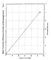
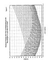
- the secondary instrument predictions will be increasingly offset, as illustrated in Figure 1, and will also exhibit an increase in the amount of prediction variability (random errors), as illustrated in Figure 2.
- the present invention provides a method of calibrating the wavelength of the secondary instrument or device to improve the accuracy and reproducibility of the predictions based on measurements by the target or secondary instrument and the transferred calibration algorithm.
- the target device can also be the primary device, a period of time after the primary device was originally calibrated. In doing so, the wavelength calibration method of the present invention reduces both the offset and the prediction variability in the secondary or target device predictions to within much more acceptable levels.
- the present invention is based, in part, on the realization that once a calibration algorithm is determined for a primary instrument, prediction of measurements on the secondary instruments using this algorithm affects the magnitude of spectral residuals. According to a preferred embodiment of the present invention, the method may be carried out as follows.
- wavelength calibration parameters P n1 , P n2 , ...P nN are separately obtained for each of the primary and the secondary instruments.
- the wavelength calibration parameters for the primary instrument are determined contemporaneously with or at approximately the same time as generation of the calibration model therefor. These parameters are obtained by using wavelength calibration radiation sources of known wavelengths with each instrument and determining the pixel location corresponding to the known wavelength of each source used. In general, at least two sources, and two wavelength calibration parameters, are required for the purposes of the present invention.
- first and second laser wavelength calibration sources having wavelengths of 632 nm and 1064 nm respectively could be used.
- the pixel locations corresponding to the laser sources are then recorded for each of the primary and the secondary instruments to provide the wavelength calibration parameters (P n1 and P n2 ).
- such laser sources are generally only capable, at best, of an accuracy of about 0.2 nm. Consequently, it is often likely that the initial wavelength calibration parameters obtained for the secondary instrument will not provide sufficient accuracy for many spectroscopic applications.
- a primary or reference wavetable is generated for the primary device and an initial secondary wavetable is generated for the secondary device.
- the wavetables essentially provide the correlation between the pixel locations of the specific device and wavelength.
- the wavetables may be generated by a number of possible analytical fitting techniques including linear and trigonometric methods. For example, in a linear fit one pixel maps to a constant wavelength difference, e.g. 2 nm/pixel.
- the spectral responses or spectra measured by each instrument for a typical or representative sample are collected next.
- the set of measured spectral components provided by the reference (primary) and secondary instruments are hereinafter referred to as S ref and S sec respectively.
- S ref and S sec The particular choice of sample used for these measurements is not key.
- a Finger Phantom® available from Nonin Medical, Inc. can optionally be used.
- the spectra measured by the secondary instrument S sec is then interpolated from the initial secondary wavetable to the reference wavetable.
- the spectral components measured by the secondary instrument are interpolated on to the reference wavetable, so that the secondary spectral components correspond to the reference pixel locations.
- the secondary spectral components provide the secondary pixel locations; the secondary pixel locations are interpolated to specific wavelengths, as provided by the secondary wavetable; and those wavelengths are (inversely) interpolated to reference pixel locations, as provided by the reference wavetable.
- This interpolation may be based on any one of a number of possible interpolation techniques such a linear interpolation, trigonometric interpolation, and Savitsky-Golay smoothed derivative techniques. Whichever wavetable generation technique is chosen, that technique is preferably used consistently throughout other interpolation steps in the present invention.
- the difference between the secondary spectral components (as they correspond to the reference pixel locations) and the primary or reference spectral components S ref is taken next.
- This spectral difference is then interpolated back to the secondary wavetable - in reverse manner to the interpolation just described above - to provide a spectral difference S dif corresponding to the secondary wavetable.
- a photometric correction for the secondary measurements is provided.
- the above provides a relatively coarse correction, however this is nonetheless sufficient, for the purposes of the present invention, to adequately compensate for physical differences between the primary and secondary instruments, such as differences in the instruments' photodiode detectors.
- the spectral difference S dif need not be recalculated during the iterative steps of the present invention.
- the photometrically corrected secondary spectral measurements ( S sec - S dif ) are then interpolated from the initial secondary wavetable to the reference wavetable (similar to as was done above for the raw secondary spectral measurements) to provide a corrected set of measured spectral data S* sec for the secondary instrument that is suitable for subsequent comparison and analysis, as described below.
- the wavelength calibration parameters P n1 , P n2 , ...P nN (i.e. the pixel positions corresponding to the calibration source wavelengths) for the secondary instrument are iteratively adjusted until an optimum set of wavelength calibration parameters (and corresponding wavetable) is arrived at.
- the secondary wavetable is regenerated and the corrected set of measured spectral data S* sec for the secondary instrument is adjusted.
- Determination of the optimal set of wavelength calibration parameters is found by minimizing a parameter representative of the spectral residuals of the secondary instrument (which varies with each set of wavelength calibration parameters).
- the spectral residuals are defined as the difference between the corrected set of measured spectral data S* rec and an estimated set of spectral data X sec for the secondary instrument.
- the parameter used to assess the spectral residuals is the sum of the absolute values of all residual components across a spectrum of interest.
- other parameters representative of the overall spectral residuals could be used such as the mean, median, or root mean square of the absolute values of some or all residual components.
- the sum of the spectral residuals is preferably calculated using the full range of the instrument spectrum, where accurate calibration is desired and measurements are sensitive over the entire instrument range. Also, if the end (or other) regions of the spectrums are overly noisy, it may be desirable to exclude these regions from spectral residual consideration. Generally, however, any spectral region of interest can be chosen for spectral residual evaluation and consideration.
- the spectral residuals can be calculated, during each iteration, using several possible factor analysis or multivariate regression techniques. These include principal components regression (PCR), principle components analysis (PCA), and partial least squares (PLS).
- PCR principal components regression
- PCA principle components analysis
- PLS partial least squares
- PCA principal components analysis
- Principal components analysis is a well known method commonly used to reduce the dimensionality of a matrix of measured data, simplifying computations while preserving as much as of the original data information as possible.
- the scores matrix T provides information about the spectral patterns in the measurement data, whereas the loadings matrix P reflects the influence of each of the various parameters in the spectral patterns.
- the matrix product T P T effectively provides an estimate of the spectral response, with the difference between the measured response S and the estimated response T P T being the spectral residuals matrix E (containing the individual spectral residual components).
- the dimension k represents the number of principal components used in the decomposition and is a matter of computational choice.
- the principal components are created in order of decreasing variance, i.e. the first principal component accounts for the most variance in the data, the second principal component accounts for the next greatest amount of variance in the data, and so on.
- the PCA is an orthogonal transform (i.e. it provides an orthogonal basis)
- Figure 3 shows an exemplary plot of the spectral residuals for a NIR photodiode array spectrophotometer having a 256 pixel array and operable to provide a spectral response between about 600 nm and 1100 nm.
- a secondary wavetable is calculated as described above.
- the difference matrix S dif nor the photometrically corrected secondary spectral measurements ( S sec - S dif ) for each distinct set of wavelength calibration parameters. Indeed, this is preferably not done for simplicity.
- the interpolation of the photometrically corrected secondary spectral measurements from the recalculated secondary wavetable to the reference wavetable is re-performed with each iteration or change in wavelength calibration parameters.
- the corrected set of measured spectral data for the secondary instrument, S* sec is adjusted with each iteration, despite the fact that the photometric correction is preferably not re-performed.
- the corresponding spectral residuals matrix E sec of the secondary spectral data is then determined in the above-described manner.
- determination of the optimal set of wavelength calibration parameters is found by minimizing a parameter representative of the spectral residuals E sec of the secondary instrument.
- the absolute values of some or all of the residual components in the spectral residuals matrix E sec are summed, and the summed value provides the parameter to be minimized during iterations.
- other parameters representative of the overall spectral residuals could be used such as the mean, median, or root mean square of the absolute values of all residual components.
- spectral residuals matrix E sec it is desirable to use all or most of the residual components in the spectral residuals matrix E sec for the absolute value calculation when the full range of the spectral instruments is of interest (i.e. measurements are sensitive to all parts of the available spectrum). Furthermore, if some small spectral regions (e.g. the upper and lower limits of the instrument's spectrum) are adversely affected by noise, it may be desirable to exclude these regions from spectral residual consideration. Generally, however, any spectral region of interest can be chosen for spectral residual evaluation and consideration. In such a case, only the components in the spectral residuals matrix E sec corresponding to those regions are assessed (e.g. only the absolute value of those components are summed).
- the pixel locations corresponding to the wavelength calibration parameters P n1 and P n2 can be individually step-wise adjusted in any suitably-sized steps. For instance, adjustment by 0.02 pixels per step can provide greatly improved wavelength calibration.
- FIGS. 4 and 5 illustrate the application of the method of the present invention to a calibration model transfer between NIR photodiode array spectrophotometers having a 256 pixel array and operable to provide a spectral response between about 600 nm and 1100 nm.
- the laser source 1 referred to in Figure 4 and the laser source 2 referred to in Figure 5 may have wavelengths of 632 nm and 1064 nm respectively.
- Each of these Figures graphically illustrates the change in the sum of the absolute value of spectral residual components for the specific wavelength calibration parameter.
- the minimum for P n1 corresponding to laser source 1 is approximately at 24.64 pixels.
- the minimum for P n2 corresponding to laser source 2 is approximately at 236.98 pixels.
- the present invention provides a more accurate determination of the pixel locations of the calibration wavelengths located on the secondary or target instrument.
- the inventors have found that the iterative wavelength calibration method of the present invention can provide accuracy that is an order of magnitude better than wavelength calibration using laser calibration sources alone (as is typically done in the prior art).
- a wavetable can be artificially generated and that both the reference spectral response and the initial target spectral response may be interpolated to the same artificially generated wavetable to measure a spectral difference between them.
- both this spectral difference and the initial target response may be interpolated to the same artificially generated wavetable or another artificially generated wavetable, and the spectral difference may be subtracted from the initial target spectral response, so as to provide a photometrically corrected target spectral response.
- this photometrically corrected target spectral response and the reference spectral response may be interpolated on to one of the artificially generated wavetables or yet another artificially generated wavetable to provide a corrected set of measured spectral data for the target instrument.
- the method according to the present invention can be used to recalibrate the primary instrument itself, where a reference set of wavelength calibration parameters has been previously obtained for the primary instrument (i.e. the "target" instrument is the primary instrument in this case).
- a reference set of wavelength calibration parameters has been previously obtained for the primary instrument (i.e. the "target” instrument is the primary instrument in this case).
- the sample used to obtain the reference set of wavelength calibration parameters is stable for the recalibration procedure after the passage of time, or that the sample can be accurately reproduced in a controlled manner.
- the sample used for calibration may be a synthetic rather than a patient sample which may become unstable over a relatively short period of time.
Landscapes
- Physics & Mathematics (AREA)
- Spectroscopy & Molecular Physics (AREA)
- General Physics & Mathematics (AREA)
- Chemical & Material Sciences (AREA)
- Pathology (AREA)
- Analytical Chemistry (AREA)
- Biochemistry (AREA)
- General Health & Medical Sciences (AREA)
- Health & Medical Sciences (AREA)
- Immunology (AREA)
- Life Sciences & Earth Sciences (AREA)
- Engineering & Computer Science (AREA)
- Mathematical Physics (AREA)
- Theoretical Computer Science (AREA)
- Spectrometry And Color Measurement (AREA)
- Investigating Or Analysing Materials By Optical Means (AREA)
- Optical Modulation, Optical Deflection, Nonlinear Optics, Optical Demodulation, Optical Logic Elements (AREA)
Claims (14)
- Une méthode d'étalonnage de la longueur d'onde d'un instrument cible, ledit instrument cible étant muni d'un modèle d'étalonnage développé pour un instrument primaire, la méthode comportant :(a) obtenir un ensemble de référence d'au moins deux paramètres d'étalonnage de longueur d'onde comportant au moins deux emplacements de pixel dans l'instrument primaire correspondant à au moins deux sources de rayonnement de longueur d'onde connue, et générer une table d'onde de référence à partir de l'ensemble de référence de paramètres d'étalonnage, la table d'onde de référence fournissant une corrélation entre les emplacements de pixel et les longueurs d'onde correspondantes dans l'instrument primaire ;(b) obtenir un ensemble cible d'au moins deux paramètres d'étalonnage de longueur d'onde correspondants comportant au moins deux emplacements de pixel dans l'instrument cible correspondant à ces au moins deux sources de rayonnement de longueur d'onde connue, et générer une table d'onde cible à partir de l'ensemble cible de paramètres d'étalonnage, la table d'onde cible fournissant une corrélation entre les emplacements de pixel et les longueurs d'onde correspondantes dans l'instrument cible ;(c) mesurer une réponse spectrale de référence d'un échantillon avec l'instrument primaire ;(d) mesurer une réponse spectrale cible dudit échantillon avec l'instrument cible ;(e) générer un ensemble corrigé de données spectrales mesurées pour l'instrument cible en utilisant la table d'onde de référence, la table d'onde cible, la réponse spectrale de référence, et la réponse spectrale cible ;(f) déterminer des résidus spectraux correspondant à l'ensemble cible de paramètres d'étalonnage de longueur d'onde, les résidus spectraux étant la différence entre l'ensemble corrigé de données spectrales mesurées et un ensemble estimé de données spectrales pour l'instrument cible ;(g) répéter les étapes (a) à (f) pour une, ou plus d'une itération, dans laquelle les emplacements de pixel de l'instrument cible sont ajustés de façon itérative pour chacune de cette ou plus d'une itérations, et(h) déterminer un ensemble optimum de paramètres d'étalonnage de longueur d'onde en minimisant un paramètre représentatif des résidus spectraux pour chaque ensemble cible de paramètres d'étalonnage de longueur d'onde.
- La méthode selon la revendication 1, dans laquelle l'étape (c) comporte mesurer des longueurs d'onde de la réponse spectrale de référence sur un détecteur de référence dans ledit instrument primaire et l'étape (d) comporte mesurer des longueurs d'onde de la réponse spectrale cible sur un détecteur cible dans ledit instrument cible.
- La méthode selon la revendication 2, dans laquelle ledit détecteur de référence et ledit détecteur cible sont chacun un détecteur formant matrice de photodiodes, et chacun desdits détecteurs formant matrices de photodiodes comporte une pluralité de pixels pour détecter lesdites longueurs d'onde.
- La méthode selon les revendications 1, 2 ou 3, comportant de plus : interpoler la réponse spectrale cible mesurée par l'instrument cible sur la table d'onde de référence ; et mesurer une différence spectrale entre la réponse spectrale cible interpolée et la réponse spectrale de référence.
- La méthode selon la revendication 4, comportant de plus : interpoler la différence spectrale en retour vers la table d'onde cible ; et soustraire la différence spectrale de la réponse spectrale cible, de façon à fournir une réponse spectrale cible corrigée de façon photométrique.
- La méthode selon la revendication 5, comportant de plus : interpoler la réponse spectrale cible corrigée de façon photométrique de la table d'onde cible à la table d'onde de référence pour fournir un ensemble corrigé de données spectrales mesurées pour l'instrument cible.
- Une méthode selon les revendications 1, 2 ou 3, comportant de plus : interpoler à la fois la réponse spectrale cible mesurée par l'instrument cible et la réponse spectrale de référence mesurée par l'instrument de référence sur une table d'onde sélectionnée ; et mesurer une différence spectrale entre la réponse spectrale cible interpolée et la réponse spectrale de référence interpolée dans ladite table d'onde sélectionnée.
- Une méthode selon la revendication 7, comportant de plus : interpoler à la fois la différence spectrale et la réponse spectrale cible sur une table d'onde sélectionnée ; et soustraire la différence spectrale de la réponse spectrale cible, de façon à fournir une réponse spectrale cible corrigée de façon photométrique.
- Une méthode selon la revendication 8, comportant de plus : interpoler à la fois la réponse spectrale cible corrigée de façon photométrique et la réponse spectrale de référence provenant de la table de référence sur une table d'onde sélectionnée, de façon à fournir un ensemble corrigé de données spectrales mesurées pour l'instrument cible.
- La méthode selon n'importe laquelle des revendications 1 à 9, dans laquelle le paramètre représentatif des résidus spectraux est la somme des valeurs absolues de tous les composants résiduels sur tout un spectre d'intérêt.
- La méthode selon n'importe laquelle des revendications 1 à 9, dans laquelle le paramètre représentatif des résidus spectraux est soit la moyenne, soit la médiane, soit la moyenne quadratique des valeurs absolues d'au moins certains composants résiduels.
- La méthode selon la revendication 10 ou la revendication 11, dans laquelle les résidus spectraux sont calculés, durant chaque itération, en utilisant soit la régression des composants principaux, soit l'analyse des composants principaux, soit les moindres carrés partiels.
- La méthode selon n'importe laquelle des revendications 1 à 12, dans laquelle les emplacements de pixel du détecteur de l'instrument cible sont ajustés de façon itérative d'une manière échelonnée dans des étapes prédéterminées.
- La méthode selon n'importe laquelle des revendications 1 à 13, dans laquelle les étapes (b) et (d) ont lieu après les étapes (a) et (c), et l'instrument cible est l'instrument primaire.
Applications Claiming Priority (3)
| Application Number | Priority Date | Filing Date | Title |
|---|---|---|---|
| US15942899P | 1999-10-14 | 1999-10-14 | |
| US159428P | 1999-10-14 | ||
| PCT/CA2000/001182 WO2001027572A1 (fr) | 1999-10-14 | 2000-10-13 | Procede pour optimiser l'etalonnage d'une longueur d'onde |
Publications (2)
| Publication Number | Publication Date |
|---|---|
| EP1221028A1 EP1221028A1 (fr) | 2002-07-10 |
| EP1221028B1 true EP1221028B1 (fr) | 2005-10-26 |
Family
ID=22572584
Family Applications (1)
| Application Number | Title | Priority Date | Filing Date |
|---|---|---|---|
| EP00965704A Expired - Lifetime EP1221028B1 (fr) | 1999-10-14 | 2000-10-13 | Procede pour optimiser l'etalonnage d'une longueur d'onde |
Country Status (6)
| Country | Link |
|---|---|
| EP (1) | EP1221028B1 (fr) |
| JP (1) | JP2003511687A (fr) |
| AT (1) | ATE308034T1 (fr) |
| CA (1) | CA2386184C (fr) |
| DE (1) | DE60023534T2 (fr) |
| WO (1) | WO2001027572A1 (fr) |
Families Citing this family (7)
| Publication number | Priority date | Publication date | Assignee | Title |
|---|---|---|---|---|
| JP4533527B2 (ja) * | 2000-12-05 | 2010-09-01 | アンリツ株式会社 | 光スペクトラムアナライザおよびその波長校正方法 |
| KR102172914B1 (ko) * | 2019-06-07 | 2020-11-03 | 한국생산기술연구원 | 라만 스펙트럼 식별 고속 탐색 방법 및 장치 |
| CN116358714A (zh) * | 2023-02-21 | 2023-06-30 | 苏州鼎芯光电科技有限公司 | 半导体激光器波长的测试方法、系统、装置 |
| CN117647498A (zh) * | 2023-11-08 | 2024-03-05 | 中国农业大学 | 一种牛奶的中红外光谱不同仪器标准化参数的获取方法 |
| CN118960957B (zh) * | 2024-08-07 | 2025-04-18 | 中检易兴元科技(北京)有限公司 | 基于光谱一致性的仪器校准方法、系统、介质及装置 |
| CN119354896B (zh) * | 2024-12-23 | 2025-03-11 | 北京德开医药科技有限公司 | 基于样品光谱数据的制药生产成品成分检测方法及系统 |
| CN121347429B (zh) * | 2025-12-19 | 2026-04-07 | 浙江大学 | 一种基于吸光度匹配的波长标定方法及系统 |
Family Cites Families (9)
| Publication number | Priority date | Publication date | Assignee | Title |
|---|---|---|---|---|
| US4866644A (en) * | 1986-08-29 | 1989-09-12 | Shenk John S | Optical instrument calibration system |
| US5559728A (en) * | 1990-10-09 | 1996-09-24 | University Of Washington | Calibration transfer for second order analytical instruments |
| US5459677A (en) * | 1990-10-09 | 1995-10-17 | Board Of Regents Of The University Of Washington | Calibration transfer for analytical instruments |
| US5347475A (en) * | 1991-09-20 | 1994-09-13 | Amoco Corporation | Method for transferring spectral information among spectrometers |
| JPH0674823A (ja) * | 1992-08-27 | 1994-03-18 | Kubota Corp | 分光分析計の波長校正方法 |
| EP0663997B1 (fr) * | 1992-10-07 | 1996-05-29 | Ashland Oil, Inc. | Etalonnage d'instrument spectroscopique |
| JPH07333141A (ja) * | 1994-06-06 | 1995-12-22 | Canon Inc | 測定方法 |
| JP3694029B2 (ja) * | 1995-02-09 | 2005-09-14 | フォス アナリティカル アクティーゼルスカブ | 分光計の標準化方法 |
| FR2734360B1 (fr) * | 1995-05-19 | 1997-07-04 | Elf Antar France | Procede de correction d'un signal delivre par un instrument de mesure |
-
2000
- 2000-10-13 EP EP00965704A patent/EP1221028B1/fr not_active Expired - Lifetime
- 2000-10-13 JP JP2001530537A patent/JP2003511687A/ja active Pending
- 2000-10-13 WO PCT/CA2000/001182 patent/WO2001027572A1/fr not_active Ceased
- 2000-10-13 DE DE60023534T patent/DE60023534T2/de not_active Expired - Lifetime
- 2000-10-13 CA CA002386184A patent/CA2386184C/fr not_active Expired - Fee Related
- 2000-10-13 AT AT00965704T patent/ATE308034T1/de not_active IP Right Cessation
Also Published As
| Publication number | Publication date |
|---|---|
| ATE308034T1 (de) | 2005-11-15 |
| CA2386184A1 (fr) | 2001-04-19 |
| CA2386184C (fr) | 2010-01-19 |
| EP1221028A1 (fr) | 2002-07-10 |
| DE60023534T2 (de) | 2006-07-27 |
| JP2003511687A (ja) | 2003-03-25 |
| DE60023534D1 (de) | 2005-12-01 |
| WO2001027572A1 (fr) | 2001-04-19 |
Similar Documents
| Publication | Publication Date | Title |
|---|---|---|
| US6700661B1 (en) | Method of optimizing wavelength calibration | |
| JP7266063B2 (ja) | 全血ヘモグロビンパラメータ又は全血ビリルビンパラメータを測定するための吸光度測定システムに搭載可能な置換可能キュベット組立体 | |
| Bouveresse et al. | Improvement of the piecewise direct standardisation procedure for the transfer of NIR spectra for multivariate calibration | |
| US6983176B2 (en) | Optically similar reference samples and related methods for multivariate calibration models used in optical spectroscopy | |
| Cushing et al. | Spextool: a spectral extraction package for SpeX, a 0.8–5.5 micron cross‐dispersed spectrograph | |
| US7436511B2 (en) | Analyte filter method and apparatus | |
| Hutsebaut et al. | Evaluation of an accurate calibration and spectral standardization procedure for Raman spectroscopy | |
| CA2286093C (fr) | Procede de normalisation de spectrometres raman pour permettre des etalonnages stables et transferables | |
| EP1496350A2 (fr) | Procédé et dispositif pour produire des jeux de base s'utilisant en analyse spectrométrique | |
| US20180224334A1 (en) | High accuracy absorbance spectrophotometers | |
| Swierenga et al. | Comparison of two different approaches toward model transferability in NIR spectroscopy | |
| US5014216A (en) | Concentration determination with multiple wavelength flash photometers | |
| EP1279025A2 (fr) | Procedes et appareil de transfert de modele d'etalonnage spectroscopique | |
| US11287384B2 (en) | System and method for improving calibration transfer between multiple raman analyzer installations | |
| Luypaert et al. | An evaluation of direct orthogonal signal correction and other preprocessing methods for the classification of clinical study lots of a dermatological cream | |
| Zhang et al. | Ridge regression combined with model complexity analysis for near infrared (NIR) spectroscopic model updating | |
| CA2386184C (fr) | Procede pour optimiser l'etalonnage d'une longueur d'onde | |
| CN113795748A (zh) | 用于配置光谱测定装置的方法 | |
| WO2000071980A9 (fr) | Procede et systeme pour l'interpretation adaptative de donnees spectrometriques, combinee a un reetalonnage continu | |
| Westerhaus | Equation development | |
| Firago et al. | Diffuse Reflectance Spectrophotometers Based on C12880MA and C11708MA Mini-Spectrometers Hamamatsu | |
| WO2006058741A1 (fr) | Spectrophotometre | |
| Ramadan et al. | Addressing temperature variations of miniaturized NIR spectrometers: Advancing quantitative models for pharmaceutical analysis | |
| Dunko et al. | Moisture assay of an antifungal by near-infrared diffuse reflectance spectroscopy | |
| Tsuta | Development of a compound-eye spectrometer for calibration-transfer-free spectroscopy |
Legal Events
| Date | Code | Title | Description |
|---|---|---|---|
| PUAI | Public reference made under article 153(3) epc to a published international application that has entered the european phase |
Free format text: ORIGINAL CODE: 0009012 |
|
| 17P | Request for examination filed |
Effective date: 20020405 |
|
| AK | Designated contracting states |
Kind code of ref document: A1 Designated state(s): AT BE CH CY DE DK ES FI FR GB GR IE IT LI LU MC NL PT SE |
|
| AX | Request for extension of the european patent |
Free format text: AL;LT;LV;MK;RO;SI |
|
| RIN1 | Information on inventor provided before grant (corrected) |
Inventor name: CADELL, THEODORE, E. Inventor name: LU, GENG |
|
| 17Q | First examination report despatched |
Effective date: 20040202 |
|
| GRAP | Despatch of communication of intention to grant a patent |
Free format text: ORIGINAL CODE: EPIDOSNIGR1 |
|
| RAP1 | Party data changed (applicant data changed or rights of an application transferred) |
Owner name: NIR DIAGNOSTICS INC. |
|
| GRAS | Grant fee paid |
Free format text: ORIGINAL CODE: EPIDOSNIGR3 |
|
| GRAA | (expected) grant |
Free format text: ORIGINAL CODE: 0009210 |
|
| AK | Designated contracting states |
Kind code of ref document: B1 Designated state(s): AT BE CH CY DE DK ES FI FR GB GR IE IT LI LU MC NL PT SE |
|
| PG25 | Lapsed in a contracting state [announced via postgrant information from national office to epo] |
Ref country code: IT Free format text: LAPSE BECAUSE OF FAILURE TO SUBMIT A TRANSLATION OF THE DESCRIPTION OR TO PAY THE FEE WITHIN THE PRESCRIBED TIME-LIMIT;WARNING: LAPSES OF ITALIAN PATENTS WITH EFFECTIVE DATE BEFORE 2007 MAY HAVE OCCURRED AT ANY TIME BEFORE 2007. THE CORRECT EFFECTIVE DATE MAY BE DIFFERENT FROM THE ONE RECORDED. Effective date: 20051026 Ref country code: AT Free format text: LAPSE BECAUSE OF FAILURE TO SUBMIT A TRANSLATION OF THE DESCRIPTION OR TO PAY THE FEE WITHIN THE PRESCRIBED TIME-LIMIT Effective date: 20051026 Ref country code: NL Free format text: LAPSE BECAUSE OF FAILURE TO SUBMIT A TRANSLATION OF THE DESCRIPTION OR TO PAY THE FEE WITHIN THE PRESCRIBED TIME-LIMIT Effective date: 20051026 Ref country code: FI Free format text: LAPSE BECAUSE OF FAILURE TO SUBMIT A TRANSLATION OF THE DESCRIPTION OR TO PAY THE FEE WITHIN THE PRESCRIBED TIME-LIMIT Effective date: 20051026 Ref country code: LI Free format text: LAPSE BECAUSE OF FAILURE TO SUBMIT A TRANSLATION OF THE DESCRIPTION OR TO PAY THE FEE WITHIN THE PRESCRIBED TIME-LIMIT Effective date: 20051026 Ref country code: CH Free format text: LAPSE BECAUSE OF FAILURE TO SUBMIT A TRANSLATION OF THE DESCRIPTION OR TO PAY THE FEE WITHIN THE PRESCRIBED TIME-LIMIT Effective date: 20051026 Ref country code: BE Free format text: LAPSE BECAUSE OF FAILURE TO SUBMIT A TRANSLATION OF THE DESCRIPTION OR TO PAY THE FEE WITHIN THE PRESCRIBED TIME-LIMIT Effective date: 20051026 |
|
| REG | Reference to a national code |
Ref country code: GB Ref legal event code: FG4D |
|
| REG | Reference to a national code |
Ref country code: CH Ref legal event code: EP |
|
| REG | Reference to a national code |
Ref country code: IE Ref legal event code: FG4D |
|
| REF | Corresponds to: |
Ref document number: 60023534 Country of ref document: DE Date of ref document: 20051201 Kind code of ref document: P |
|
| PG25 | Lapsed in a contracting state [announced via postgrant information from national office to epo] |
Ref country code: GR Free format text: LAPSE BECAUSE OF FAILURE TO SUBMIT A TRANSLATION OF THE DESCRIPTION OR TO PAY THE FEE WITHIN THE PRESCRIBED TIME-LIMIT Effective date: 20060126 Ref country code: DK Free format text: LAPSE BECAUSE OF FAILURE TO SUBMIT A TRANSLATION OF THE DESCRIPTION OR TO PAY THE FEE WITHIN THE PRESCRIBED TIME-LIMIT Effective date: 20060126 Ref country code: SE Free format text: LAPSE BECAUSE OF FAILURE TO SUBMIT A TRANSLATION OF THE DESCRIPTION OR TO PAY THE FEE WITHIN THE PRESCRIBED TIME-LIMIT Effective date: 20060126 |
|
| PG25 | Lapsed in a contracting state [announced via postgrant information from national office to epo] |
Ref country code: ES Free format text: LAPSE BECAUSE OF FAILURE TO SUBMIT A TRANSLATION OF THE DESCRIPTION OR TO PAY THE FEE WITHIN THE PRESCRIBED TIME-LIMIT Effective date: 20060206 |
|
| PG25 | Lapsed in a contracting state [announced via postgrant information from national office to epo] |
Ref country code: PT Free format text: LAPSE BECAUSE OF FAILURE TO SUBMIT A TRANSLATION OF THE DESCRIPTION OR TO PAY THE FEE WITHIN THE PRESCRIBED TIME-LIMIT Effective date: 20060327 |
|
| NLV1 | Nl: lapsed or annulled due to failure to fulfill the requirements of art. 29p and 29m of the patents act | ||
| REG | Reference to a national code |
Ref country code: CH Ref legal event code: PL |
|
| ET | Fr: translation filed | ||
| PLBE | No opposition filed within time limit |
Free format text: ORIGINAL CODE: 0009261 |
|
| STAA | Information on the status of an ep patent application or granted ep patent |
Free format text: STATUS: NO OPPOSITION FILED WITHIN TIME LIMIT |
|
| 26N | No opposition filed |
Effective date: 20060727 |
|
| PG25 | Lapsed in a contracting state [announced via postgrant information from national office to epo] |
Ref country code: IE Free format text: LAPSE BECAUSE OF NON-PAYMENT OF DUE FEES Effective date: 20061013 |
|
| REG | Reference to a national code |
Ref country code: FR Ref legal event code: CA |
|
| PG25 | Lapsed in a contracting state [announced via postgrant information from national office to epo] |
Ref country code: MC Free format text: LAPSE BECAUSE OF NON-PAYMENT OF DUE FEES Effective date: 20061031 |
|
| REG | Reference to a national code |
Ref country code: IE Ref legal event code: MM4A |
|
| PG25 | Lapsed in a contracting state [announced via postgrant information from national office to epo] |
Ref country code: LU Free format text: LAPSE BECAUSE OF NON-PAYMENT OF DUE FEES Effective date: 20061013 |
|
| PG25 | Lapsed in a contracting state [announced via postgrant information from national office to epo] |
Ref country code: CY Free format text: LAPSE BECAUSE OF FAILURE TO SUBMIT A TRANSLATION OF THE DESCRIPTION OR TO PAY THE FEE WITHIN THE PRESCRIBED TIME-LIMIT Effective date: 20051026 |
|
| PGFP | Annual fee paid to national office [announced via postgrant information from national office to epo] |
Ref country code: FR Payment date: 20101004 Year of fee payment: 11 |
|
| PGFP | Annual fee paid to national office [announced via postgrant information from national office to epo] |
Ref country code: GB Payment date: 20100920 Year of fee payment: 11 |
|
| PGFP | Annual fee paid to national office [announced via postgrant information from national office to epo] |
Ref country code: DE Payment date: 20101028 Year of fee payment: 11 |
|
| GBPC | Gb: european patent ceased through non-payment of renewal fee |
Effective date: 20111013 |
|
| REG | Reference to a national code |
Ref country code: FR Ref legal event code: ST Effective date: 20120629 |
|
| PG25 | Lapsed in a contracting state [announced via postgrant information from national office to epo] |
Ref country code: DE Free format text: LAPSE BECAUSE OF NON-PAYMENT OF DUE FEES Effective date: 20120501 |
|
| REG | Reference to a national code |
Ref country code: DE Ref legal event code: R119 Ref document number: 60023534 Country of ref document: DE Effective date: 20120501 |
|
| PG25 | Lapsed in a contracting state [announced via postgrant information from national office to epo] |
Ref country code: GB Free format text: LAPSE BECAUSE OF NON-PAYMENT OF DUE FEES Effective date: 20111013 Ref country code: FR Free format text: LAPSE BECAUSE OF NON-PAYMENT OF DUE FEES Effective date: 20111102 |