EP1221320A2 - Procédé de composition d'une ligne de perfusion - Google Patents
Procédé de composition d'une ligne de perfusion Download PDFInfo
- Publication number
- EP1221320A2 EP1221320A2 EP01130664A EP01130664A EP1221320A2 EP 1221320 A2 EP1221320 A2 EP 1221320A2 EP 01130664 A EP01130664 A EP 01130664A EP 01130664 A EP01130664 A EP 01130664A EP 1221320 A2 EP1221320 A2 EP 1221320A2
- Authority
- EP
- European Patent Office
- Prior art keywords
- unit
- spike
- infusion
- infusion line
- units
- Prior art date
- Legal status (The legal status is an assumption and is not a legal conclusion. Google has not performed a legal analysis and makes no representation as to the accuracy of the status listed.)
- Ceased
Links
- 238000001802 infusion Methods 0.000 title claims abstract description 90
- 238000000034 method Methods 0.000 title claims description 23
- 239000007924 injection Substances 0.000 claims abstract description 37
- 238000002347 injection Methods 0.000 claims abstract description 37
- 239000012530 fluid Substances 0.000 claims description 14
- 239000008280 blood Substances 0.000 claims description 5
- 210000004369 blood Anatomy 0.000 claims description 5
- 239000003978 infusion fluid Substances 0.000 claims description 5
- 239000000126 substance Substances 0.000 claims description 5
- 238000004519 manufacturing process Methods 0.000 description 5
- 239000000203 mixture Substances 0.000 description 3
- 241000894006 Bacteria Species 0.000 description 1
- 241000700605 Viruses Species 0.000 description 1
- 230000004872 arterial blood pressure Effects 0.000 description 1
- 230000036772 blood pressure Effects 0.000 description 1
- 210000001124 body fluid Anatomy 0.000 description 1
- 239000010839 body fluid Substances 0.000 description 1
- 238000001631 haemodialysis Methods 0.000 description 1
- 230000000322 hemodialysis Effects 0.000 description 1
- 239000012510 hollow fiber Substances 0.000 description 1
- 238000012544 monitoring process Methods 0.000 description 1
- 239000002245 particle Substances 0.000 description 1
- 238000011144 upstream manufacturing Methods 0.000 description 1
Images


Classifications
-
- A—HUMAN NECESSITIES
- A61—MEDICAL OR VETERINARY SCIENCE; HYGIENE
- A61M—DEVICES FOR INTRODUCING MEDIA INTO, OR ONTO, THE BODY; DEVICES FOR TRANSDUCING BODY MEDIA OR FOR TAKING MEDIA FROM THE BODY; DEVICES FOR PRODUCING OR ENDING SLEEP OR STUPOR
- A61M5/00—Devices for bringing media into the body in a subcutaneous, intra-vascular or intramuscular way; Accessories therefor, e.g. filling or cleaning devices, arm-rests
- A61M5/14—Infusion devices, e.g. infusing by gravity; Blood infusion; Accessories therefor
-
- A—HUMAN NECESSITIES
- A61—MEDICAL OR VETERINARY SCIENCE; HYGIENE
- A61M—DEVICES FOR INTRODUCING MEDIA INTO, OR ONTO, THE BODY; DEVICES FOR TRANSDUCING BODY MEDIA OR FOR TAKING MEDIA FROM THE BODY; DEVICES FOR PRODUCING OR ENDING SLEEP OR STUPOR
- A61M39/00—Tubes, tube connectors, tube couplings, valves, access sites or the like, specially adapted for medical use
- A61M39/02—Access sites
-
- A—HUMAN NECESSITIES
- A61—MEDICAL OR VETERINARY SCIENCE; HYGIENE
- A61M—DEVICES FOR INTRODUCING MEDIA INTO, OR ONTO, THE BODY; DEVICES FOR TRANSDUCING BODY MEDIA OR FOR TAKING MEDIA FROM THE BODY; DEVICES FOR PRODUCING OR ENDING SLEEP OR STUPOR
- A61M39/00—Tubes, tube connectors, tube couplings, valves, access sites or the like, specially adapted for medical use
- A61M39/22—Valves or arrangement of valves
- A61M39/24—Check- or non-return valves
-
- A—HUMAN NECESSITIES
- A61—MEDICAL OR VETERINARY SCIENCE; HYGIENE
- A61M—DEVICES FOR INTRODUCING MEDIA INTO, OR ONTO, THE BODY; DEVICES FOR TRANSDUCING BODY MEDIA OR FOR TAKING MEDIA FROM THE BODY; DEVICES FOR PRODUCING OR ENDING SLEEP OR STUPOR
- A61M5/00—Devices for bringing media into the body in a subcutaneous, intra-vascular or intramuscular way; Accessories therefor, e.g. filling or cleaning devices, arm-rests
- A61M5/14—Infusion devices, e.g. infusing by gravity; Blood infusion; Accessories therefor
- A61M5/162—Needle sets, i.e. connections by puncture between reservoir and tube ; Connections between reservoir and tube
-
- A—HUMAN NECESSITIES
- A61—MEDICAL OR VETERINARY SCIENCE; HYGIENE
- A61M—DEVICES FOR INTRODUCING MEDIA INTO, OR ONTO, THE BODY; DEVICES FOR TRANSDUCING BODY MEDIA OR FOR TAKING MEDIA FROM THE BODY; DEVICES FOR PRODUCING OR ENDING SLEEP OR STUPOR
- A61M5/00—Devices for bringing media into the body in a subcutaneous, intra-vascular or intramuscular way; Accessories therefor, e.g. filling or cleaning devices, arm-rests
- A61M5/14—Infusion devices, e.g. infusing by gravity; Blood infusion; Accessories therefor
- A61M5/165—Filtering accessories, e.g. blood filters, filters for infusion liquids
Definitions
- the present invention generally relates to a method of composing an infusion line or transfusion line used as a conduit line for connecting a supply source of a medical fluid to a member for access to a patient such as a catheter, an injection needle and so on.
- the present invention relates to a method of composing the infusion line capable of performing simply the operation of combining various components to compose the infusion line.
- the term "infusion line” is used so as to have a meaning that includes "transfusion line”.
- infusion lines are used.
- an infusion line is used as a part of an arterial pressure measuring line for monitoring a blood pressure, or in some cases, a part of an infusion line is used as a blood collecting line.
- Methods of using such infusion lines differ from each other depending on hospitals, doctors or other medical staffs, and various kind of application. Therefore a large number of specifications of infusion lines are employed actually.
- infusion lines as mentioned above are so-called custom-made articles and are not used for general purposes, so that components thereof cannot be exchanged between infusion lines with different specifications. Accordingly, infusion tubes, functional elements, and connecting tools are made into many different shapes, sizes, or functions, to meet various different demands on clinical sites, and various kinds of infusion lines are manufactured by using different combinations thereof.
- JP63(1988)-95063A discloses a system in which a circuit for an extracorporeal circulation process of a body fluid such as hemodialysis is configured according to the following steps: Several kinds of block configurations are made by unifying two or more functional parts into one block configuration; and some selected ones of the block configurations are combined to compose an infusion line. That system makes it possible to standardize components and manufacture the circuit easily to some extent. However, since the components incorporated into the block configurations are fixed, a circuit system has less flexibility in configuration and cannot meet diversified demands sufficiently.
- a method of composing an infusion line according to the present invention includes the following steps:
- Components for forming the infusion line are classified into unit groups including a spike unit, a main tube unit, an injection device unit, an infusion filter unit, and a one-way valve unit.
- Plural kinds of units are provided for each unit group according to different specifications, each unit being formed of one or more components combined based on a function of the respective unit.
- a combination of the unit groups is determined by allowing the spike unit and the main tube unit to be indispensable and selecting at least one of the unit groups from the remaining unit groups.
- An arrangement of the selected unit groups is determined, with the spike unit being positioned at one end thereof.
- At least one kind of the units is selected from each of the unit group based on the determined combination.
- the selected units are combined according to the determined arrangement to compose the infusion line, with the end on the distal side relative to the spike unit being composed of a connector used for a connection to a member for access to a patient.
- the infusion line it is possible to systematize the infusion line reasonably as the combination of a plurality of units based on the basic functions of respective elements and to perform simply the operation of composing an infusion line that meets users' demands by selecting the standardized units. Since each unit has compatibility and is made uniform, reduction in cost due to simplification of a production system becomes possible.
- the unit groups may further include an extension tube unit, and when the extension tube unit is selected as one of the unit groups composing the inision line, the arrangement of the selected unit groups is determined with the extension tube unit being positioned at the end on the distal side relative to the spike unit.
- the combination of the unit groups may be determined with the extension tube unit being included in the indispensable units.
- the spike unit may be positioned at an end portion on a medical fluid side of the infusion line and may have a function of connecting the infusion line to a supply source of a medical fluid via a spike.
- the main tube unit may be connected to the spike unit and may have a function of being used for adjusting a length between the spike unit and another unit positioned on a patient side.
- the injection device unit may be positioned between the main tube unit and the extension tube unit and may have a function of being used for injecting the medical fluid or collecting blood.
- the infusion filter unit may be positioned between the main tube unit and the extension tube unit and may have a function of being used for removing foreign substances (particles).
- the one-way valve unit may be positioned between the main tube unit and the extension tube unit and adjacent to the injection device unit and may have a function of preventing a back flow of an infusion fluid.
- the extension tube unit may be positioned at an end portion on the patient side and may have a function of allowing the infusion line to be held at hand of the patient easily.
- the spike unit may include a spike and a drip chamber as the components for forming the unit group.
- the main tube unit may include a tube, a damp for controlling flow rate, and a connector.
- the injection device unit may include a connector and at least one of an injection port and a three-way stop cock.
- the infusion filter unit may include an I-V filter, a tube for connection, and a connector.
- the one-way valve unit may include a one-way valve and a connector.
- the extension tube unit may include a tube and a connector.
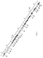
- FIG. 1 is a plan view showing an infusion line, with sections of respective units being indicated according to a first embodiment of the present invention.
- FIGs. 2A to 2F are views showing examples of a spike unit in the infusion line of FIG. 1.
- FIGs 3Ato 3G are views showing examples of a main tube unit in the infusion line of FIG. 1.
- FIGs. 4A to 4F are views showing examples of an injection device unit in the infusion line of FIG. 1.
- FIGs. 5A to 5B are views showing examples of a one-way valve unit in the infusion line of FIG. 1.
- FIGs. 6A to 6C are views showing examples of an infusion filter unit in the infusion line of FIG. 1.
- FIGs. 7A to 7G are views showing examples of an extension tube unit in the infusion line of FIG. 1.
- FIG. 8 is a plan view showing an infusion line, with sections of respective units being indicated according to a second embodiment of the present invention.
- FIG. 1 shows a composition of an infusion line in a first embodiment according to the present invention, in which sections of respective units are indicated in order to describe a method of composing the infusion line.
- components for forming the infusion line are classified into six unit groups and combined with each other so as to form several kinds of standardized units in each unit group, and a plurality of units selected from the unit groups are combined to compose the standardized infusion line.
- the infusion line is divided into the unit groups such as a group of a spike unit 1, a group of a main tube unit 2, a group of an injection device unit 3, a group of an infusion filter unit 4, a group of a one-way valve unit 5, and a group of an extension tube unit 6.
- the unit groups are selected according to a function of an infusion line, respective units are selected appropriately from the selected unit groups, and the selected units are combined.
- indispensable units are selected from each of the spike unit 1, the main tube unit 2, and the extension tube unit 6.
- at least one kind of unit is selected from the injection device unit 3, the infusion filter unit 4, and the one-way valve unit 5.
- the spike unit 1 is positioned at one end of the infusion line and the extension tube unit 6 is positioned at the other end
- the other units are, for example, interposed between the main tube unit 2 and the extension tube unit 6. Aplurality of the same kind of units may be selected from each of the selected unit group.
- unit means the combination of components for realizing the function of each unit. However, one unit may be formed of one component.
- spike unit 1 or "main tube unit 2", etc., means the names of the respective unit groups.
- the functions of units included in each unit group and the standard configurations of those units, i.e., the combination of components are as follows.
- the spike unit 1 includes a spike 10 and a drip chamber 11 as the components.
- the spike unit 1 is positioned at an end portion on a medical fluid side (the distal side relative to a patient) and has a function of connecting the infusion line to a supply source of the medical fluid via the spike 10.
- the main tube unit 2 includes a tube 20, a clamp 21 for controlling a flow rate, and a connector 22 as the components.
- the main tube unit 2 is connected to the spike unit 1 and is used for adjusting a length between the spike unit 1 and another unit positioned on a patient side.
- the injection device unit 3 includes an injection port 30 and connectors 31 and 32 as the components. In some cases, in place of the injection port 30, a three-way stop cock (not shown) is used for the injection device unit 3.
- the injection device unit 3 is positioned between the main tube unit 2 and the extension tube unit 6. As shown in FIG. 1, in some cases, a plurality of injection device units 3 are used.
- the injection device unit 3 is used for injecting the medical fluid or collecting blood from the injection port or the three-way stop cock.
- the infusion filter unit 4 includes a I-V filter 40 of a hollow fiber type, a connection tube 41, a clamp 42, and connectors 43 and 44 as the components.
- the clamp 42 is not indispensable for this unit, it is preferable that the unit includes the clamp 42 in order to fill up a fluid rapidly into a housing of the filter or remove air bubble easily.
- the infusion filter unit 4 is positioned between the main tube unit 2 and the extension tube unit 6 and is used for removing foreign substances.
- the foreign substances include junk of gums or corks, air bubbles, bacteria, virus, or the like.
- the one-way valve unit 5 includes a one-way valve 50 and connectors 51 and 52 as the components. If required, the one-way valve unit 5 includes a tube 53. This unit is used for preventing a back flow of an infusion fluid and is positioned adjacent to the injection device unit 3 whereby the infusion fluid is prevented from flowing back in the line when a fluid is charged or withdrawn via the injection device unit 3. This unit may be positioned at the upstream or downstream of the injection device unit 3, so long as the position is adjacent to it.
- the extension tube unit 6 includes a tube 60, a connector 61 for being connected to a member for access to a patient such as an injection needle or an catheter, and a connector 62 for being connected to another unit, as the components.
- the extension tube unit 6 is positioned at the end portion on a patient side and has a function of allowing the infusion line to be held at the hand of the patient easily.
- the connector 61 may be either of a lure connector or a lock connector. That is, a free lock nut 63 is not an indispensable component. However, it is preferable that the free lock nut 63 is provided so as to be able to lock the connection between the connector 61 and the access member, since thereby it is avoided that the connector 61 is disconnected accidentally from the access member.
- the infusion line is produced according to the method of the present invention, some of the unit groups are selected to determine the combination, and then appropriate units are selected from the respective selected unit groups, so that the combination of the units is determined.
- the configuration of the infusion line described in the first embodiment includes all of the elements (units) required for a usual practical use.
- the extension tube unit 6 as shown in Fig.8, depending on the purpose of using the infusion line.
- a connector forming the end of a unit positioned at the end on a patient side i.e. the distal side relative to the spike unit 1
- the connector 61 used for the connection with the member for access to a patient is provided at the end of the one-way valve unit 5.
- the present invention it is possible to compose an infusion line by using standardized units, while adopting users' various demands. Furthermore, it is possible to perform simply the operation for composing an infusion line that meets the users' demands by only selecting standardized units. Since each unit has compatibility and is made uniform, reduction in cost due to simplification of the production system can be achieved.
Landscapes
- Health & Medical Sciences (AREA)
- Vascular Medicine (AREA)
- Engineering & Computer Science (AREA)
- Anesthesiology (AREA)
- Biomedical Technology (AREA)
- Heart & Thoracic Surgery (AREA)
- Hematology (AREA)
- Life Sciences & Earth Sciences (AREA)
- Animal Behavior & Ethology (AREA)
- General Health & Medical Sciences (AREA)
- Public Health (AREA)
- Veterinary Medicine (AREA)
- Infusion, Injection, And Reservoir Apparatuses (AREA)
Applications Claiming Priority (2)
| Application Number | Priority Date | Filing Date | Title |
|---|---|---|---|
| JP2000394867 | 2000-12-26 | ||
| JP2000394867 | 2000-12-26 |
Publications (2)
| Publication Number | Publication Date |
|---|---|
| EP1221320A2 true EP1221320A2 (fr) | 2002-07-10 |
| EP1221320A3 EP1221320A3 (fr) | 2002-07-31 |
Family
ID=18860429
Family Applications (1)
| Application Number | Title | Priority Date | Filing Date |
|---|---|---|---|
| EP01130664A Ceased EP1221320A3 (fr) | 2000-12-26 | 2001-12-21 | Procédé de composition d'une ligne de perfusion |
Country Status (4)
| Country | Link |
|---|---|
| US (1) | US20020079258A1 (fr) |
| EP (1) | EP1221320A3 (fr) |
| KR (1) | KR20020053026A (fr) |
| CN (1) | CN1362266A (fr) |
Cited By (3)
| Publication number | Priority date | Publication date | Assignee | Title |
|---|---|---|---|---|
| WO2004047887A1 (fr) * | 2002-11-26 | 2004-06-10 | Terumo Kabushiki Kaisha | Tube de transfusion de liquide et ensemble tube de transfusion de liquide |
| WO2005061030A1 (fr) * | 2003-12-09 | 2005-07-07 | Becton, Dickinson And Company | Seringue de rinçage a butee anti-reflux |
| US9522237B2 (en) | 2005-01-07 | 2016-12-20 | Becton, Dickinson And Company | Positive displacement flush syringe |
Families Citing this family (9)
| Publication number | Priority date | Publication date | Assignee | Title |
|---|---|---|---|---|
| CN101785882B (zh) * | 2010-02-10 | 2012-04-11 | 天津市博奥天盛塑材有限公司 | 一次性注射药液免穿刺体外循环血路组件结构 |
| US9364651B2 (en) | 2010-02-23 | 2016-06-14 | Smiths Medical Asd, Inc. | Adapter with special fitting |
| US9220833B2 (en) | 2011-06-27 | 2015-12-29 | Smiths Medical Asd, Inc. | Medicament infusion systems |
| US8870238B2 (en) * | 2011-06-27 | 2014-10-28 | Smiths Medical Asd, Inc. | Fitting for medicament infusion systems |
| US10737087B2 (en) | 2012-04-17 | 2020-08-11 | Smiths Medical Asd, Inc. | Filling fitting |
| KR101395087B1 (ko) * | 2013-04-12 | 2014-05-16 | 한국엔테랄푸드(주) | 경장영양을 위한 경관급식용 유동식 공급장치 |
| DE202013101695U1 (de) | 2013-04-19 | 2013-05-07 | B. Braun Avitum Ag | Rezirkulationsvorrichtung eines extrakorporalen Blutbehandlungsgeräts |
| CN103239776A (zh) * | 2013-04-26 | 2013-08-14 | 德清县新德意医疗器械有限公司 | 一种一次性使用精密过滤延长管 |
| US20180243501A1 (en) * | 2015-09-08 | 2018-08-30 | Kobayashi & Co., Ltd. | Infusion set |
Citations (1)
| Publication number | Priority date | Publication date | Assignee | Title |
|---|---|---|---|---|
| JPS6395063A (ja) | 1986-10-09 | 1988-04-26 | 旭メデイカル株式会社 | 組立式体液処理セツト |
Family Cites Families (6)
| Publication number | Priority date | Publication date | Assignee | Title |
|---|---|---|---|---|
| US4006745A (en) * | 1975-05-22 | 1977-02-08 | Sorenson Research Co., Inc. | Autologous transfusion system and method |
| US4552556A (en) * | 1981-11-27 | 1985-11-12 | Alza Corporation | Parenteral controlled therapy |
| US5059173A (en) * | 1990-04-04 | 1991-10-22 | Sacco John J | IV apparatus |
| US5743894A (en) * | 1995-06-07 | 1998-04-28 | Sherwood Medical Company | Spike port with integrated two way valve access |
| US5807312A (en) * | 1997-05-23 | 1998-09-15 | Dzwonkiewicz; Mark R. | Bolus pump apparatus |
| US6200289B1 (en) * | 1998-04-10 | 2001-03-13 | Milestone Scientific, Inc. | Pressure/force computer controlled drug delivery system and the like |
-
2001
- 2001-12-21 EP EP01130664A patent/EP1221320A3/fr not_active Ceased
- 2001-12-24 US US10/035,730 patent/US20020079258A1/en not_active Abandoned
- 2001-12-24 CN CN01138178A patent/CN1362266A/zh active Pending
- 2001-12-26 KR KR1020010085033A patent/KR20020053026A/ko not_active Withdrawn
Patent Citations (1)
| Publication number | Priority date | Publication date | Assignee | Title |
|---|---|---|---|---|
| JPS6395063A (ja) | 1986-10-09 | 1988-04-26 | 旭メデイカル株式会社 | 組立式体液処理セツト |
Cited By (5)
| Publication number | Priority date | Publication date | Assignee | Title |
|---|---|---|---|---|
| WO2004047887A1 (fr) * | 2002-11-26 | 2004-06-10 | Terumo Kabushiki Kaisha | Tube de transfusion de liquide et ensemble tube de transfusion de liquide |
| US7901386B2 (en) | 2002-11-26 | 2011-03-08 | Terumo Kabushiki Kaisha | Liquid transfusing tube and liquid transfusing tube set |
| WO2005061030A1 (fr) * | 2003-12-09 | 2005-07-07 | Becton, Dickinson And Company | Seringue de rinçage a butee anti-reflux |
| US9522237B2 (en) | 2005-01-07 | 2016-12-20 | Becton, Dickinson And Company | Positive displacement flush syringe |
| US10105494B2 (en) | 2005-01-07 | 2018-10-23 | Becton, Dickinson And Company | Positive displacement flush syringe |
Also Published As
| Publication number | Publication date |
|---|---|
| EP1221320A3 (fr) | 2002-07-31 |
| KR20020053026A (ko) | 2002-07-04 |
| CN1362266A (zh) | 2002-08-07 |
| US20020079258A1 (en) | 2002-06-27 |
Similar Documents
| Publication | Publication Date | Title |
|---|---|---|
| EP1221320A2 (fr) | Procédé de composition d'une ligne de perfusion | |
| CA2920538C (fr) | Systeme d'ensemble de perfusion intraveineuse muni d'un collecteur de derivation | |
| EP0805694B1 (fr) | Vanne anti-contamination croisee et systemes d'administration de fluide utilisant celle-ci | |
| US6620119B1 (en) | Reusable blood lines | |
| US8087702B2 (en) | Connector for a dialysis port | |
| US9220833B2 (en) | Medicament infusion systems | |
| JPS6029150A (ja) | 血液採取装置 | |
| US20040236286A1 (en) | One-to-many infiltration tubing | |
| JPWO2017163787A1 (ja) | 医療用コネクタ、輸液セット及び流体の採取方法 | |
| JP2002253669A (ja) | 輸液ラインの構成方法 | |
| US20190269848A1 (en) | IV Extension Set or IV Set System with Bypass Manifold | |
| WO2005042069A1 (fr) | Connecteur | |
| EP3842086B1 (fr) | Raccord de tube, circuit de circulation extracorporelle et dispositif de purification de sang | |
| JP3976209B2 (ja) | プライミング装置、ならびに同装置に併用される使い捨て用接続チューブの使用方法 | |
| EP2783719B1 (fr) | Connecteur d'embout Luer ventilé | |
| CN221286599U (zh) | 带有多通阀体的医用导管 | |
| CN223350700U (zh) | 一种用于微量泵的延长管 | |
| CN211751454U (zh) | 一种带有多个三通阀的输液组件 | |
| CN215023791U (zh) | 一种多瓶轮流自动输液器 | |
| US20250213844A1 (en) | System and method for tapered luer connector for medical tubing | |
| DE202005015741U1 (de) | Medizinische Hahnbank | |
| CN2678661Y (zh) | 气压连通自换式输液器 | |
| WO2003080156A1 (fr) | Dispositif de protection medical contre les debranchements | |
| JPWO2000018452A1 (ja) | 流量可変装置を備えた携帯型ディスポーサブル注入ポンプ |
Legal Events
| Date | Code | Title | Description |
|---|---|---|---|
| PUAI | Public reference made under article 153(3) epc to a published international application that has entered the european phase |
Free format text: ORIGINAL CODE: 0009012 |
|
| PUAL | Search report despatched |
Free format text: ORIGINAL CODE: 0009013 |
|
| AK | Designated contracting states |
Kind code of ref document: A2 Designated state(s): AT BE CH CY DE DK ES FI FR GB GR IE IT LI LU MC NL PT SE TR |
|
| AX | Request for extension of the european patent |
Free format text: AL;LT;LV;MK;RO;SI |
|
| AK | Designated contracting states |
Kind code of ref document: A3 Designated state(s): AT BE CH CY DE DK ES FI FR GB GR IE IT LI LU MC NL PT SE TR |
|
| AX | Request for extension of the european patent |
Free format text: AL;LT;LV;MK;RO;SI |
|
| RIC1 | Information provided on ipc code assigned before grant |
Free format text: 7A 61M 5/14 A, 7A 61M 5/162 B, 7A 61M 5/165 B, 7A 61M 5/168 B, 7A 61M 39/24 B, 7A 61M 1/00 B |
|
| 17P | Request for examination filed |
Effective date: 20020809 |
|
| AKX | Designation fees paid |
Designated state(s): DE FR GB IT SE |
|
| 17Q | First examination report despatched |
Effective date: 20030701 |
|
| STAA | Information on the status of an ep patent application or granted ep patent |
Free format text: STATUS: THE APPLICATION HAS BEEN REFUSED |
|
| 18R | Application refused |
Effective date: 20041122 |