EP1221387A2 - Schutvorrichtung für die Kupplung zwischen zwei Fahrzeugen - Google Patents
Schutvorrichtung für die Kupplung zwischen zwei Fahrzeugen Download PDFInfo
- Publication number
- EP1221387A2 EP1221387A2 EP01129779A EP01129779A EP1221387A2 EP 1221387 A2 EP1221387 A2 EP 1221387A2 EP 01129779 A EP01129779 A EP 01129779A EP 01129779 A EP01129779 A EP 01129779A EP 1221387 A2 EP1221387 A2 EP 1221387A2
- Authority
- EP
- European Patent Office
- Prior art keywords
- vehicle
- coupling
- stop
- protection device
- baffle plate
- Prior art date
- Legal status (The legal status is an assumption and is not a legal conclusion. Google has not performed a legal analysis and makes no representation as to the accuracy of the status listed.)
- Granted
Links
- 230000008878 coupling Effects 0.000 claims abstract description 47
- 238000010168 coupling process Methods 0.000 claims abstract description 47
- 238000005859 coupling reaction Methods 0.000 claims abstract description 47
- 230000001681 protective effect Effects 0.000 claims abstract description 22
- 238000011161 development Methods 0.000 description 4
- 230000018109 developmental process Effects 0.000 description 4
- 230000001154 acute effect Effects 0.000 description 2
- 238000005553 drilling Methods 0.000 description 2
- 230000003116 impacting effect Effects 0.000 description 2
- 230000006978 adaptation Effects 0.000 description 1
- 230000015572 biosynthetic process Effects 0.000 description 1
- 238000010276 construction Methods 0.000 description 1
- 230000000694 effects Effects 0.000 description 1
- 238000005516 engineering process Methods 0.000 description 1
- 238000004519 manufacturing process Methods 0.000 description 1
- 239000002184 metal Substances 0.000 description 1
- 230000001459 mortal effect Effects 0.000 description 1
- 239000007787 solid Substances 0.000 description 1
- 239000000725 suspension Substances 0.000 description 1
Images
Classifications
-
- B—PERFORMING OPERATIONS; TRANSPORTING
- B60—VEHICLES IN GENERAL
- B60D—VEHICLE CONNECTIONS
- B60D1/00—Traction couplings; Hitches; Draw-gear; Towing devices
- B60D1/58—Auxiliary devices
- B60D1/60—Covers, caps or guards, e.g. comprising anti-theft devices
Definitions
- the invention relates to a protective device for the Coupling between two vehicles according to the preamble of Claim 1.
- the drawbar can slide sideways or under it Towing vehicle take place. If there is an unstable side wall there is also the risk that the drawbar e.g. over one Enter the loading area into a loading area in the towing vehicle can, resulting in the same danger as described above results.
- the object of the invention is one compared to the prior art Technology to propose improved protection.
- the invention is characterized in that the baffle plate arranged at the level of the coupling and with at least one height stop is provided to prevent sliding of the coupling element of the vehicle to be coupled to the to prevent the vehicle from standing.
- Baffle plate provides effective collision protection for the Operator on the clutch without an additional Buffer is provided. The collision protection results in that the coupling element of the to be engaged Vehicle slides against the height stop when sliding and further sliding is reliably prevented. On lateral sliding is also due to the Side stops not possible.
- the Height stop designed as a lower stop.
- the coupling element of the vehicle to be engaged under the stationary vehicle prevented according to the invention is an underride of the coupling element of the vehicle to be engaged under the stationary vehicle prevented according to the invention. It is particularly when attaching of trailers on towing and pushing vehicles is an advantage which the trailer's drawbar can move downwards is, as is often the case with in-house used, so-called industrial trucks, is the case.
- Such vehicles are usually with a jaw coupling provided for engaging a drawbar eye.
- the drawbar hits the baffle plate, from where they slide to one of the stops can.
- the additional bottom stop reliably prevents the drawbar from pulling or Push truck underrun. That way stays ensures a distance between both vehicles is secured by the drawbar length.
- the dimensioning the baffle plate is to be made so that also at angled drawbar when hitting one of the A sufficient safety distance between there is a squeezing of the two vehicles Operator prevented.
- a upper stop provided. Such an upper stop is then makes sense when the drawbar suspension of the drawbar Game allowed up to close to vertical or when building the corresponding train or Push vehicle also allows the drawbar to be driven over, for example with a loading platform with missing or unstable final drop side. In this case the Drawbar when sliding upwards through the upper one Caught stop, the invention Safety distance is guaranteed.
- the upper and / or lower stop as a strip-shaped web educated.
- the invention Security effect for any dimension Coupling elements, such as drawbar eyes guaranteed.
- the formation of a stop as a strip-shaped web also simplifies production and increases stability.
- a continuous all-round stop frame is provided.
- Such a stop frame for example, by a closed connection of four strip-shaped stops, i.e. the two side stops as well as the upper and the lower stop is producible, ensures the impact Coupling element in all possible sliding directions from and is of great stability due to its closed shape.
- baffle plate according to the invention circumferential stop frame is however not on one limited to a square shape, for example it could also be a oval or circular training can be provided. Also a conical shape of the baffle plate is without the invention to agree further.
- the side stops are dimensioned and are aligned that when the Coupling element, e.g. a drawbar eye one Trailer drawbar, this is reliably caught.
- the above angular arrangement is also on one closed stop frame transferable so that in one special embodiment of the stop frame throughout at least vertically or inclined towards the coupling is trained.
- the baffle plate according to the invention can be used on all suitable construction elements of a vehicle attached as long as it is ensured that in the event of a miss the coupling the impacting coupling element Baffle hits.
- the Baffle plate advantageously between which the Baffle carrying vehicle and the associated Coupling element attached. The baffle is therefore in Direction of impact seen behind the clutch, causing it is reliably ensured that the clutch missing coupling element securely on the baffle plate incident.
- the device according to the invention can be assembled here be greatly simplified if the same Fasteners are used for fastening serve the clutch.
- a jaw coupling on Bolted to the rear of a vehicle with bolts so can a protective device according to the invention easily behind the jaw coupling placed and screwed together with this are, where appropriate the corresponding holes in the baffle plate must be provided.
- the protective device and the vehicle coupling as a structural unit trained, which is to be assembled as a whole. So can for example a jaw coupling with the baffle plate protection device according to the invention be welded.
- the Vehicle-side assembly is again carried out in one Assembly step by attaching the complete assembly becomes.
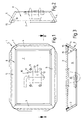
- the device 1 according to FIG. 1 includes a baffle plate two side stops 3, 4 and an upper stop 5 and a lower stop 6.
- the stops 3, 4, 5, 6 are on their junctions 7 to a circumferential closed Stop frame 8 welded.
- the holes 9 are like this arranged to match the drilling pattern of a jaw coupling 10 correspond, their position with dashed lines is shown.
- the jaw coupling 10 comprises an upper and lower leg 11, 12, which are connected via a base plate 13 and have a hole for a plug pin 14. They don't towing eye of a trailer drawbar shown in the Maulkupplung 10 inserted between the legs 11, 12 and then fixed by inserting the plug pin 14 become.
- the baffle is made 2 and the two stops 3, 4, 5, 6 made of solid sheet metal, the all around with an outer weld 15 and one inner weld 16 are welded. Also the Junction 7 can be realized in the form of a weld seam become.
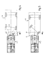
- the function of the protective device 1 is shown in FIG. 4 illustrated.
- the protective device 1 is on one Traction vehicle 17 attached to which to hang a trailer 18 is.
- the trailer 18 has a front axle 19, which has a only indicated by dashed tiller 20 in the usual way is rotatable to steer the trailer 18.
- a towing eye 21 which is intended for inclusion in a jaw coupling 10.
- FIG. 5 the previous case is without a protective device 1 shown. Due to the forward movement of the trailer 18 the drawbar 20 turned sideways while the towing eye 21 slid along the rear of the vehicle. Here is the Trailer 18 almost completely on the towing vehicle 17th opened until it has hit the jaw coupling 10. An operator who is between these two vehicles 17, 18 according to FIG. 5 and is not out in time the space between towing vehicle 17 and trailer 18 can remove is between the two vehicles 17, 18th pinched. Depending on the slope and trailer load there is a risk to life for the operator.
- the protective device according to the invention does not require any Adaptation to the trailer 18 to be coupled and is also as Retrofit part simply to existing couplings 10 from Towing vehicles 17 to install.
- the invention is not limited to the constellation of Embodiment of a towing vehicle with a trailer, it is useful wherever there are two Vehicles must be coupled together and there is a risk of that by sliding a coupling element away Minimum distance is guaranteed for any operators, i.e. for example also on push vehicles.
Landscapes
- Engineering & Computer Science (AREA)
- Transportation (AREA)
- Mechanical Engineering (AREA)
- Body Structure For Vehicles (AREA)
- Seal Device For Vehicle (AREA)
- Motorcycle And Bicycle Frame (AREA)
- Coupling Device And Connection With Printed Circuit (AREA)
- Agricultural Machines (AREA)
Abstract
Description
- Figur 1
- eine Draufsicht auf eine erfindungsgemäße Schutzvorrichtung,
- Figur 2
- eine Seitenansicht einer erfindungsgemäßen Schutzvorrichtung,
- Figur 3
- eine Schnittdarstellung einer erfindungsgemäßen Schutzvorrichtung,
- Figur 4
- eine skizzenhafte Draufsicht auf ein Fahrzeuggespann mit erfindungsgemäßer Schutzvorrichtung und
- Figur 5
- eine Draufsicht auf ein Fahrzeuggespann ohne erfindungsgemäße Schutzvorrichtung.
- 1
- Vorrichtung
- 2
- Prallplatte
- 3
- Seitenanschlag
- 4
- Seitenanschlag
- 5
- oberer Anschlag
- 6
- unterer Anschlag
- 7
- Verbindungsstellen
- 8
- Anschlagrahmen
- 9
- Bohrung
- 10
- Maulkupplung
- 11
- Schenkel
- 12
- Schenkel
- 13
- Grundplatte
- 14
- Steckbolzen
- 15
- äußere Schweißnaht
- 16
- innere Schweißnaht
- 17
- Zugfahrzeug
- 18
- Anhänger
- 19
- Vorderachse
- 20
- Deichsel
- 21
- Zugöse
Claims (13)
- Schutzvorrichtung für die Kupplung zwischen zwei Fahrzeugen, insbesondere für die Anhängerkupplung eines Zugoder Schubfahrzeugs, wobei eine Prallplatte mit seitlichen Anschlägen vorgesehen ist, um ein anzukuppelndes Fahrzeug aufzuhalten, dadurch gekennzeichnet, dass die Prallplatte (2) auf Höhe der Kupplung (10) angeordnet und mit wenigstens einem Höhenanschlag (6) versehen ist, um ein Abgleiten des Kupplungselements (20) des anzukuppelnden Fahrzeugs (18) am stehenden Fahrzeug (17) zu verhindern.
- Schutzvorrichtung nach Anspruch 1, dadurch gekennzeichnet, dass der Höhenanschlag als unterer Anschlag (6) ausgebildet ist.
- Schutzvorrichtung nach Anspruch 1 oder 2, dadurch gekennzeichnet, dass zusätzlich ein oberer Anschlag (5) vorgesehen ist.
- Schutzvorrichtung nach einem der vorgenannten Ansprüche, dadurch gekennzeichnet, dass der obere und/oder der untere Anschlag (5, 6) als streifenförmiger Steg ausgebildet ist.
- Schutzvorrichtung nach einem der vorgenannten Ansprüche, dadurch gekennzeichnet, dass ein durchgehender umlaufender Anschlagrahmen (3, 4, 5, 6) vorgesehen ist.
- Schutzvorrichtung nach einem der vorgenannten Ansprüche, dadurch gekennzeichnet, dass der oder die Anschläge (3, 4, 5, 6) senkrecht zur Prallplatte (2) oder zur Kupplung (10) hin geneigt angeordnet sind.
- Schutzvorrichtung nach einem der vorgenannten Ansprüche, dadurch gekennzeichnet, dass der Anschlagrahmen (3, 4, 5, 6) durchgehend senkrecht zur Prallplatte (2) angeordnet ist.
- Schutzvorrichtung nach einem der vorgenannten Ansprüche, dadurch gekennzeichnet, dass der Anschlagrahmen (3, 4, 5, 6) durchgehend zur Kupplung (10) hin geneigt ausgebildet ist.
- Schutzvorrichtung nach einem der vorgenannten Ansprüche, dadurch gekennzeichnet, dass die Prallplatte (2) zwischen dem zugehörigen Fahrzeug (17) und der entsprechenden Kupplung (10) anbringbar ist.
- Schutzvorrichtung nach einem der vorgenannten Ansprüche, dadurch gekennzeichnet, dass sie mit den gleichen Befestigungselementen (9) wie die zugehörige Fahrzeugkupplung (10) am Fahrzeug (17) befestigbar ist.
- Schutzvorrichtung nach einem der vorgenannten Ansprüche, dadurch gekennzeichnet, dass die Schutzvorrichtung (1) und die Fahrzeugkupplung (10) als Baueinheit ausgeführt sind.
- Fahrzeug, dadurch gekennzeichnet, dass eine Schutzvorrichtung nach einem der vorgenannten Ansprüche vorgesehen ist.
- Fahrzeug, dadurch gekennzeichnet, dass eine Schutzvorrichtung nach einem der vorgenannten Ansprüche mit den gleichen Befestigungselementen (9) wie die Fahrzeugkupplung (10) an dem Fahrzeug (17) befestigt ist.
Applications Claiming Priority (2)
| Application Number | Priority Date | Filing Date | Title |
|---|---|---|---|
| DE10100371 | 2001-01-05 | ||
| DE10100371 | 2001-01-05 |
Publications (3)
| Publication Number | Publication Date |
|---|---|
| EP1221387A2 true EP1221387A2 (de) | 2002-07-10 |
| EP1221387A3 EP1221387A3 (de) | 2002-11-27 |
| EP1221387B1 EP1221387B1 (de) | 2007-03-07 |
Family
ID=7669860
Family Applications (1)
| Application Number | Title | Priority Date | Filing Date |
|---|---|---|---|
| EP01129779A Expired - Lifetime EP1221387B1 (de) | 2001-01-05 | 2001-12-14 | Schutzvorrichtung für die Kupplung zwischen zwei Fahrzeugen |
Country Status (3)
| Country | Link |
|---|---|
| EP (1) | EP1221387B1 (de) |
| AT (1) | ATE355983T1 (de) |
| DE (2) | DE10161479A1 (de) |
Family Cites Families (5)
| Publication number | Priority date | Publication date | Assignee | Title |
|---|---|---|---|---|
| US3420549A (en) * | 1967-01-11 | 1969-01-07 | Orval L Robinson | Trailer hitch-guide and guard |
| US4226438A (en) * | 1979-01-11 | 1980-10-07 | Collins Walter L | Trailer hitch guide |
| DE3915944A1 (de) * | 1989-05-02 | 1990-11-08 | Holger Jensen | Zugkugelkupplung |
| US5941551A (en) * | 1996-06-26 | 1999-08-24 | Harman; C. Eric | Ez hitch |
| DE19802629A1 (de) * | 1998-01-24 | 1999-08-05 | Daimler Chrysler Ag | Rangierschutz |
-
2001
- 2001-12-14 DE DE10161479A patent/DE10161479A1/de not_active Withdrawn
- 2001-12-14 DE DE50112156T patent/DE50112156D1/de not_active Expired - Lifetime
- 2001-12-14 EP EP01129779A patent/EP1221387B1/de not_active Expired - Lifetime
- 2001-12-14 AT AT01129779T patent/ATE355983T1/de not_active IP Right Cessation
Also Published As
| Publication number | Publication date |
|---|---|
| DE50112156D1 (de) | 2007-04-19 |
| EP1221387A3 (de) | 2002-11-27 |
| ATE355983T1 (de) | 2007-03-15 |
| EP1221387B1 (de) | 2007-03-07 |
| DE10161479A1 (de) | 2002-07-11 |
Similar Documents
| Publication | Publication Date | Title |
|---|---|---|
| DE102005039489B4 (de) | Stoßfänger für ein Kraftfahrzeug | |
| DE4415246A1 (de) | Überrollschutzsystem für ein Arbeitsfahrzeug | |
| DE102011055350B4 (de) | Unterfahrschutz zur Anbringung am Heck eines Lastkraftwagens | |
| EP1520939A2 (de) | Ladegerät | |
| DE102010000786A1 (de) | Anhängekupplung | |
| DE19934238C1 (de) | Vorrichtung zur Betätigung einer Kupplung, insbesondere für Kraftfahrzeuge | |
| EP1099575B1 (de) | Kupplungsvorrichtung für ein Kraftfahrzeug | |
| EP1132259A2 (de) | Klappbare Unterfahrschutzeinrichtung | |
| EP0743398A1 (de) | Schutzplankenstrang | |
| DE10136298B4 (de) | Pralldämpfer | |
| DE3340344C2 (de) | ||
| EP1221387B1 (de) | Schutzvorrichtung für die Kupplung zwischen zwei Fahrzeugen | |
| EP1279771A2 (de) | Fahrbahnbegrenzungseinrichtung | |
| EP0857632A2 (de) | Zugvorrichtung mit Auflaufbremseinrichtung für Kraftfahrzeuganhänger | |
| DE202009006846U1 (de) | Zusatzvorrichtung für eine Anhängerkupplung | |
| DE102017118812B4 (de) | Verstärktes Viergelenk | |
| DE102004044912A1 (de) | Anhängekupplung mit Kugelgelenk | |
| DE102014012590B4 (de) | Fahrzeugaufbau mit pendelbarer Bordwand | |
| DE102009020989A1 (de) | Zusatzvorrichtung für eine Anhängerkupplung | |
| EP4137335A1 (de) | Kupplungsaufsatz für eine kugelkopfkupplung eines kraftfahrzeugs und verfahren zum transportieren mindestens eines transportgutes mittels eines kupplungsaufsatzes | |
| DE20016473U1 (de) | Klappbare Unterfahrschutzeinrichtung | |
| DE60317306T2 (de) | Fahrzeugstruktur, und fahrzeug mit derartigen stuktur | |
| DE102007007166A1 (de) | Transportfahrzeug mit Hubladebühne und verstellbarem Unterfahrschutz | |
| DE102010000785A1 (de) | Anhängekupplung | |
| DE19840001A1 (de) | Kupplungseinrichtung |
Legal Events
| Date | Code | Title | Description |
|---|---|---|---|
| PUAI | Public reference made under article 153(3) epc to a published international application that has entered the european phase |
Free format text: ORIGINAL CODE: 0009012 |
|
| AK | Designated contracting states |
Kind code of ref document: A2 Designated state(s): AT BE CH CY DE DK ES FI FR GB GR IE IT LI LU MC NL PT SE TR |
|
| AX | Request for extension of the european patent |
Free format text: AL;LT;LV;MK;RO;SI |
|
| PUAL | Search report despatched |
Free format text: ORIGINAL CODE: 0009013 |
|
| AK | Designated contracting states |
Kind code of ref document: A3 Designated state(s): AT BE CH CY DE DK ES FI FR GB GR IE IT LI LU MC NL PT SE TR |
|
| AX | Request for extension of the european patent |
Free format text: AL;LT;LV;MK;RO;SI |
|
| 17P | Request for examination filed |
Effective date: 20030130 |
|
| AKX | Designation fees paid |
Designated state(s): AT DE IT NL |
|
| GRAP | Despatch of communication of intention to grant a patent |
Free format text: ORIGINAL CODE: EPIDOSNIGR1 |
|
| GRAS | Grant fee paid |
Free format text: ORIGINAL CODE: EPIDOSNIGR3 |
|
| GRAA | (expected) grant |
Free format text: ORIGINAL CODE: 0009210 |
|
| AK | Designated contracting states |
Kind code of ref document: B1 Designated state(s): AT DE IT NL |
|
| REF | Corresponds to: |
Ref document number: 50112156 Country of ref document: DE Date of ref document: 20070419 Kind code of ref document: P |
|
| PLBE | No opposition filed within time limit |
Free format text: ORIGINAL CODE: 0009261 |
|
| STAA | Information on the status of an ep patent application or granted ep patent |
Free format text: STATUS: NO OPPOSITION FILED WITHIN TIME LIMIT |
|
| 26N | No opposition filed |
Effective date: 20071210 |
|
| PG25 | Lapsed in a contracting state [announced via postgrant information from national office to epo] |
Ref country code: AT Free format text: LAPSE BECAUSE OF NON-PAYMENT OF DUE FEES Effective date: 20071214 |
|
| PGFP | Annual fee paid to national office [announced via postgrant information from national office to epo] |
Ref country code: NL Payment date: 20141219 Year of fee payment: 14 |
|
| PGFP | Annual fee paid to national office [announced via postgrant information from national office to epo] |
Ref country code: IT Payment date: 20141222 Year of fee payment: 14 |
|
| PGFP | Annual fee paid to national office [announced via postgrant information from national office to epo] |
Ref country code: DE Payment date: 20150123 Year of fee payment: 14 |
|
| REG | Reference to a national code |
Ref country code: DE Ref legal event code: R119 Ref document number: 50112156 Country of ref document: DE |
|
| REG | Reference to a national code |
Ref country code: NL Ref legal event code: MM Effective date: 20160101 |
|
| PG25 | Lapsed in a contracting state [announced via postgrant information from national office to epo] |
Ref country code: DE Free format text: LAPSE BECAUSE OF NON-PAYMENT OF DUE FEES Effective date: 20160701 Ref country code: NL Free format text: LAPSE BECAUSE OF NON-PAYMENT OF DUE FEES Effective date: 20160101 |
|
| PG25 | Lapsed in a contracting state [announced via postgrant information from national office to epo] |
Ref country code: IT Free format text: LAPSE BECAUSE OF NON-PAYMENT OF DUE FEES Effective date: 20151214 |