EP1221389A2 - Dispositif de climatisation pour véhicule automobile - Google Patents
Dispositif de climatisation pour véhicule automobile Download PDFInfo
- Publication number
- EP1221389A2 EP1221389A2 EP01127612A EP01127612A EP1221389A2 EP 1221389 A2 EP1221389 A2 EP 1221389A2 EP 01127612 A EP01127612 A EP 01127612A EP 01127612 A EP01127612 A EP 01127612A EP 1221389 A2 EP1221389 A2 EP 1221389A2
- Authority
- EP
- European Patent Office
- Prior art keywords
- evaporator
- air
- refrigerant
- conditioning system
- air conditioning
- Prior art date
- Legal status (The legal status is an assumption and is not a legal conclusion. Google has not performed a legal analysis and makes no representation as to the accuracy of the status listed.)
- Granted
Links
Images
Classifications
-
- F—MECHANICAL ENGINEERING; LIGHTING; HEATING; WEAPONS; BLASTING
- F28—HEAT EXCHANGE IN GENERAL
- F28D—HEAT-EXCHANGE APPARATUS, NOT PROVIDED FOR IN ANOTHER SUBCLASS, IN WHICH THE HEAT-EXCHANGE MEDIA DO NOT COME INTO DIRECT CONTACT
- F28D20/00—Heat storage plants or apparatus in general; Regenerative heat-exchange apparatus not covered by groups F28D17/00 or F28D19/00
- F28D20/02—Heat storage plants or apparatus in general; Regenerative heat-exchange apparatus not covered by groups F28D17/00 or F28D19/00 using latent heat
-
- B—PERFORMING OPERATIONS; TRANSPORTING
- B60—VEHICLES IN GENERAL
- B60H—ARRANGEMENTS OF HEATING, COOLING, VENTILATING OR OTHER AIR-TREATING DEVICES SPECIALLY ADAPTED FOR PASSENGER OR GOODS SPACES OF VEHICLES
- B60H1/00—Heating, cooling or ventilating devices
- B60H1/00321—Heat exchangers for air-conditioning devices
-
- B—PERFORMING OPERATIONS; TRANSPORTING
- B60—VEHICLES IN GENERAL
- B60H—ARRANGEMENTS OF HEATING, COOLING, VENTILATING OR OTHER AIR-TREATING DEVICES SPECIALLY ADAPTED FOR PASSENGER OR GOODS SPACES OF VEHICLES
- B60H1/00—Heating, cooling or ventilating devices
- B60H1/00321—Heat exchangers for air-conditioning devices
- B60H1/00335—Heat exchangers for air-conditioning devices of the gas-air type
-
- B—PERFORMING OPERATIONS; TRANSPORTING
- B60—VEHICLES IN GENERAL
- B60H—ARRANGEMENTS OF HEATING, COOLING, VENTILATING OR OTHER AIR-TREATING DEVICES SPECIALLY ADAPTED FOR PASSENGER OR GOODS SPACES OF VEHICLES
- B60H1/00—Heating, cooling or ventilating devices
- B60H1/00492—Heating, cooling or ventilating devices comprising regenerative heating or cooling means, e.g. heat accumulators
- B60H1/005—Regenerative cooling means, e.g. cold accumulators
-
- B—PERFORMING OPERATIONS; TRANSPORTING
- B60—VEHICLES IN GENERAL
- B60H—ARRANGEMENTS OF HEATING, COOLING, VENTILATING OR OTHER AIR-TREATING DEVICES SPECIALLY ADAPTED FOR PASSENGER OR GOODS SPACES OF VEHICLES
- B60H1/00—Heating, cooling or ventilating devices
- B60H1/32—Cooling devices
- B60H1/3204—Cooling devices using compression
- B60H1/323—Cooling devices using compression characterised by comprising auxiliary or multiple systems, e.g. plurality of evaporators, or by involving auxiliary cooling devices
-
- C—CHEMISTRY; METALLURGY
- C09—DYES; PAINTS; POLISHES; NATURAL RESINS; ADHESIVES; COMPOSITIONS NOT OTHERWISE PROVIDED FOR; APPLICATIONS OF MATERIALS NOT OTHERWISE PROVIDED FOR
- C09K—MATERIALS FOR MISCELLANEOUS APPLICATIONS, NOT PROVIDED FOR ELSEWHERE
- C09K5/00—Heat-transfer, heat-exchange or heat-storage materials, e.g. refrigerants; Materials for the production of heat or cold by chemical reactions other than by combustion
- C09K5/02—Materials undergoing a change of physical state when used
- C09K5/04—Materials undergoing a change of physical state when used the change of state being from liquid to vapour or vice versa
- C09K5/041—Materials undergoing a change of physical state when used the change of state being from liquid to vapour or vice versa for compression-type refrigeration systems
-
- C—CHEMISTRY; METALLURGY
- C09—DYES; PAINTS; POLISHES; NATURAL RESINS; ADHESIVES; COMPOSITIONS NOT OTHERWISE PROVIDED FOR; APPLICATIONS OF MATERIALS NOT OTHERWISE PROVIDED FOR
- C09K—MATERIALS FOR MISCELLANEOUS APPLICATIONS, NOT PROVIDED FOR ELSEWHERE
- C09K5/00—Heat-transfer, heat-exchange or heat-storage materials, e.g. refrigerants; Materials for the production of heat or cold by chemical reactions other than by combustion
- C09K5/02—Materials undergoing a change of physical state when used
- C09K5/06—Materials undergoing a change of physical state when used the change of state being from liquid to solid or vice versa
- C09K5/063—Materials absorbing or liberating heat during crystallisation; Heat storage materials
-
- C—CHEMISTRY; METALLURGY
- C09—DYES; PAINTS; POLISHES; NATURAL RESINS; ADHESIVES; COMPOSITIONS NOT OTHERWISE PROVIDED FOR; APPLICATIONS OF MATERIALS NOT OTHERWISE PROVIDED FOR
- C09K—MATERIALS FOR MISCELLANEOUS APPLICATIONS, NOT PROVIDED FOR ELSEWHERE
- C09K5/00—Heat-transfer, heat-exchange or heat-storage materials, e.g. refrigerants; Materials for the production of heat or cold by chemical reactions other than by combustion
- C09K5/02—Materials undergoing a change of physical state when used
- C09K5/06—Materials undergoing a change of physical state when used the change of state being from liquid to solid or vice versa
- C09K5/066—Cooling mixtures; De-icing compositions
-
- F—MECHANICAL ENGINEERING; LIGHTING; HEATING; WEAPONS; BLASTING
- F25—REFRIGERATION OR COOLING; COMBINED HEATING AND REFRIGERATION SYSTEMS; HEAT PUMP SYSTEMS; MANUFACTURE OR STORAGE OF ICE; LIQUEFACTION SOLIDIFICATION OF GASES
- F25B—REFRIGERATION MACHINES, PLANTS OR SYSTEMS; COMBINED HEATING AND REFRIGERATION SYSTEMS; HEAT PUMP SYSTEMS
- F25B39/00—Evaporators; Condensers
- F25B39/02—Evaporators
- F25B39/022—Evaporators with plate-like or laminated elements
-
- F—MECHANICAL ENGINEERING; LIGHTING; HEATING; WEAPONS; BLASTING
- F25—REFRIGERATION OR COOLING; COMBINED HEATING AND REFRIGERATION SYSTEMS; HEAT PUMP SYSTEMS; MANUFACTURE OR STORAGE OF ICE; LIQUEFACTION SOLIDIFICATION OF GASES
- F25B—REFRIGERATION MACHINES, PLANTS OR SYSTEMS; COMBINED HEATING AND REFRIGERATION SYSTEMS; HEAT PUMP SYSTEMS
- F25B5/00—Compression machines, plants or systems, with several evaporator circuits, e.g. for varying refrigerating capacity
- F25B5/02—Compression machines, plants or systems, with several evaporator circuits, e.g. for varying refrigerating capacity arranged in parallel
-
- F—MECHANICAL ENGINEERING; LIGHTING; HEATING; WEAPONS; BLASTING
- F28—HEAT EXCHANGE IN GENERAL
- F28D—HEAT-EXCHANGE APPARATUS, NOT PROVIDED FOR IN ANOTHER SUBCLASS, IN WHICH THE HEAT-EXCHANGE MEDIA DO NOT COME INTO DIRECT CONTACT
- F28D1/00—Heat-exchange apparatus having stationary conduit assemblies for one heat-exchange medium only, the media being in contact with different sides of the conduit wall, in which the other heat-exchange medium is a large body of fluid, e.g. domestic or motor car radiators
- F28D1/02—Heat-exchange apparatus having stationary conduit assemblies for one heat-exchange medium only, the media being in contact with different sides of the conduit wall, in which the other heat-exchange medium is a large body of fluid, e.g. domestic or motor car radiators with heat-exchange conduits immersed in the body of fluid
- F28D1/04—Heat-exchange apparatus having stationary conduit assemblies for one heat-exchange medium only, the media being in contact with different sides of the conduit wall, in which the other heat-exchange medium is a large body of fluid, e.g. domestic or motor car radiators with heat-exchange conduits immersed in the body of fluid with tubular conduits
- F28D1/053—Heat-exchange apparatus having stationary conduit assemblies for one heat-exchange medium only, the media being in contact with different sides of the conduit wall, in which the other heat-exchange medium is a large body of fluid, e.g. domestic or motor car radiators with heat-exchange conduits immersed in the body of fluid with tubular conduits the conduits being straight
- F28D1/0535—Heat-exchange apparatus having stationary conduit assemblies for one heat-exchange medium only, the media being in contact with different sides of the conduit wall, in which the other heat-exchange medium is a large body of fluid, e.g. domestic or motor car radiators with heat-exchange conduits immersed in the body of fluid with tubular conduits the conduits being straight the conduits having a non-circular cross-section
- F28D1/05366—Assemblies of conduits connected to common headers, e.g. core type radiators
- F28D1/05375—Assemblies of conduits connected to common headers, e.g. core type radiators with particular pattern of flow, e.g. change of flow direction
-
- F—MECHANICAL ENGINEERING; LIGHTING; HEATING; WEAPONS; BLASTING
- F28—HEAT EXCHANGE IN GENERAL
- F28D—HEAT-EXCHANGE APPARATUS, NOT PROVIDED FOR IN ANOTHER SUBCLASS, IN WHICH THE HEAT-EXCHANGE MEDIA DO NOT COME INTO DIRECT CONTACT
- F28D7/00—Heat-exchange apparatus having stationary tubular conduit assemblies for both heat-exchange media, the media being in contact with different sides of a conduit wall
- F28D7/0008—Heat-exchange apparatus having stationary tubular conduit assemblies for both heat-exchange media, the media being in contact with different sides of a conduit wall the conduits for one medium being in heat conductive contact with the conduits for the other medium
-
- F—MECHANICAL ENGINEERING; LIGHTING; HEATING; WEAPONS; BLASTING
- F28—HEAT EXCHANGE IN GENERAL
- F28D—HEAT-EXCHANGE APPARATUS, NOT PROVIDED FOR IN ANOTHER SUBCLASS, IN WHICH THE HEAT-EXCHANGE MEDIA DO NOT COME INTO DIRECT CONTACT
- F28D7/00—Heat-exchange apparatus having stationary tubular conduit assemblies for both heat-exchange media, the media being in contact with different sides of a conduit wall
- F28D7/0008—Heat-exchange apparatus having stationary tubular conduit assemblies for both heat-exchange media, the media being in contact with different sides of a conduit wall the conduits for one medium being in heat conductive contact with the conduits for the other medium
- F28D7/0025—Heat-exchange apparatus having stationary tubular conduit assemblies for both heat-exchange media, the media being in contact with different sides of a conduit wall the conduits for one medium being in heat conductive contact with the conduits for the other medium the conduits for one medium or the conduits for both media being flat tubes or arrays of tubes
-
- F—MECHANICAL ENGINEERING; LIGHTING; HEATING; WEAPONS; BLASTING
- F25—REFRIGERATION OR COOLING; COMBINED HEATING AND REFRIGERATION SYSTEMS; HEAT PUMP SYSTEMS; MANUFACTURE OR STORAGE OF ICE; LIQUEFACTION SOLIDIFICATION OF GASES
- F25B—REFRIGERATION MACHINES, PLANTS OR SYSTEMS; COMBINED HEATING AND REFRIGERATION SYSTEMS; HEAT PUMP SYSTEMS
- F25B2400/00—Component parts or details not otherwise provided for in this subclass
- F25B2400/24—Thermal storage element
-
- F—MECHANICAL ENGINEERING; LIGHTING; HEATING; WEAPONS; BLASTING
- F25—REFRIGERATION OR COOLING; COMBINED HEATING AND REFRIGERATION SYSTEMS; HEAT PUMP SYSTEMS; MANUFACTURE OR STORAGE OF ICE; LIQUEFACTION SOLIDIFICATION OF GASES
- F25D—REFRIGERATORS; COLD ROOMS; ICE-BOXES; COOLING OR FREEZING APPARATUS NOT OTHERWISE PROVIDED FOR
- F25D16/00—Devices using a combination of a cooling mode associated with refrigerating machinery with a cooling mode not associated with refrigerating machinery
-
- F—MECHANICAL ENGINEERING; LIGHTING; HEATING; WEAPONS; BLASTING
- F28—HEAT EXCHANGE IN GENERAL
- F28D—HEAT-EXCHANGE APPARATUS, NOT PROVIDED FOR IN ANOTHER SUBCLASS, IN WHICH THE HEAT-EXCHANGE MEDIA DO NOT COME INTO DIRECT CONTACT
- F28D20/00—Heat storage plants or apparatus in general; Regenerative heat-exchange apparatus not covered by groups F28D17/00 or F28D19/00
- F28D2020/0004—Particular heat storage apparatus
- F28D2020/0013—Particular heat storage apparatus the heat storage material being enclosed in elements attached to or integral with heat exchange conduits
-
- F—MECHANICAL ENGINEERING; LIGHTING; HEATING; WEAPONS; BLASTING
- F28—HEAT EXCHANGE IN GENERAL
- F28D—HEAT-EXCHANGE APPARATUS, NOT PROVIDED FOR IN ANOTHER SUBCLASS, IN WHICH THE HEAT-EXCHANGE MEDIA DO NOT COME INTO DIRECT CONTACT
- F28D21/00—Heat-exchange apparatus not covered by any of the groups F28D1/00 - F28D20/00
- F28D2021/0019—Other heat exchangers for particular applications; Heat exchange systems not otherwise provided for
- F28D2021/008—Other heat exchangers for particular applications; Heat exchange systems not otherwise provided for for vehicles
- F28D2021/0085—Evaporators
-
- Y—GENERAL TAGGING OF NEW TECHNOLOGICAL DEVELOPMENTS; GENERAL TAGGING OF CROSS-SECTIONAL TECHNOLOGIES SPANNING OVER SEVERAL SECTIONS OF THE IPC; TECHNICAL SUBJECTS COVERED BY FORMER USPC CROSS-REFERENCE ART COLLECTIONS [XRACs] AND DIGESTS
- Y02—TECHNOLOGIES OR APPLICATIONS FOR MITIGATION OR ADAPTATION AGAINST CLIMATE CHANGE
- Y02E—REDUCTION OF GREENHOUSE GAS [GHG] EMISSIONS, RELATED TO ENERGY GENERATION, TRANSMISSION OR DISTRIBUTION
- Y02E60/00—Enabling technologies; Technologies with a potential or indirect contribution to GHG emissions mitigation
- Y02E60/14—Thermal energy storage
Definitions
- the invention relates in particular to an air conditioning system for a motor vehicle with a compressor arranged in a refrigerant circuit and a Evaporator for cooling air to be conditioned for the interior, in particular according to the preamble of claim 1 and / or Claim 2, and a heat exchanger, especially an evaporator according to the preamble of claim 12.
- the invention further relates an air conditioning system in particular according to claims 23 or 24.
- a measure to reduce fuel consumption is to switch off the engine during a temporary standstill, for example when stopping at a traffic light or in another Driving situations in which a drive power of the drive motor is not needed at least temporarily. This temporary Switching off the engine is also called idle stop operation.
- Such Measures are at least partially in today's low-consumption Vehicles, such as the so-called three-liter vehicle, already used. For vehicles that have the idle stop operating mode 25-30% of the driving time is the motor in inner-city traffic switched off.
- EP 0 995 621 A2 proposes the Evaporator of the air conditioning system through the cooling of damp air accumulating condensate, so that in idle stop operation when the Engine is switched off, the air can be cooled by the then defrosting ice.
- this method has numerous disadvantages.
- the amount of water in the air is present and necessary for the icing of the evaporator depends on the climatic environmental conditions. It can occur that with low humidity not enough condensation. water is available for icing.
- Evaporator icing usually takes a relatively long time necessary so that this well-known air conditioning system only after a relative long driving time in idle stop mode.
- Another problem is, which usually evaporates the evaporator unevenly, so that the Evaporator has iced and non-iced areas. Furthermore the icing can be so strong that the air cannot pass through the evaporator or can only flow with a high pressure drop. In any case, the Ice layer has an air-side pressure loss, which leads to increased fan performance leads.
- an additional second is according to a first solution Evaporator provided for cooling the air, this evaporator additionally contains a cold storage medium (latent cold storage).
- This second evaporator can be loaded if there is sufficient cooling capacity is available, for example in normal driving, the cold storage medium being optimal for storing cold can be coordinated.
- the air is then through it second evaporator cooled.
- This second evaporator thus forms one Combination of cold storage and evaporator and is used in the following also called storage evaporator.
- the air can also via both evaporators be directed.
- the evaporator is in at least two Sub-areas divided, with a first sub-area exclusively as Refrigerant evaporator can act and a second sub-area in addition Contains cold storage medium.
- the second section of the evaporator has thus essentially the same properties as that mentioned above Storage evaporator of the first solution. So in this second solution the functions of the evaporator while driving and the Storage evaporator in idle-stop operation in a single evaporator, a single component, integrated. Again, the maximum To provide cooling capacity, the air as a third possibility also via both Evaporators are directed.
- the storage evaporator or the storage area are preferably on the refrigerant side parallel to the first evaporator or first partial area switched, so that either the cooling capacity of the first or second Evaporator or partial area can be supplied.
- the refrigerant flow through the storage evaporator or the second section controllable by a valve.
- the air to be cooled can either be connected in parallel on the air side by both evaporators or sub-areas or by just one be performed.
- idle stop mode for example, during the When the engine is running, drive the air through the first evaporator or Partial area are cooled and the air through when the engine is switched off the storage evaporator or the second partial area are cooled.
- the Switching the air flow can be done by a front of the evaporator arranged airflow control element can be realized.
- the melting point of the cold storage medium is preferably slightly above 0 ° C, the cold storage medium especially decanol (melting point 7 ° C) or tetradecane (melting point 6 ° C) or contains.
- the cold storage medium especially decanol (melting point 7 ° C) or tetradecane (melting point 6 ° C) or contains.
- Such cold storage media are also for other storage vaporizers and / or others Circuits can be used.
- the cold storage medium is a Water Glysanthin mixture.
- the air to be cooled can either be connected in parallel on the air side by both evaporators or sub-areas or by just one be performed.
- idle stop mode for example, during the When the engine is running, drive the air through the first evaporator or Partial area are cooled and the air through when the engine is switched off the storage evaporator or the second partial area are cooled.
- the Switching the air flow can be done by a front of the evaporator arranged airflow control element can be realized.
- Fresh air and recirculation mode are advantageously possible, so that, for example, already cooled air in the interior again can be recirculated, whereby cooling capacity can be saved.
- the storage evaporator or second Subarea can be used as the evaporator tubes for the refrigerant flow Multi-channel pipes can be formed, the individual channels Cold storage medium can be stored.
- At least one refrigerant tube of this type is arranged that at least on one side of the refrigerant tube Storage for a cold storage medium is arranged.
- a memory is only arranged on one side of the refrigerant pipe.
- memory on both sides of the Refrigerant pipe can be arranged.
- the memory can also be at one Side surface is connected to the refrigerant pipe and on the other of its side surfaces is connected to a rib. Farther can the refrigerant pipe on one side surface with a memory in Connection is made and on the other of its side surfaces with a rib communicates.
- the components of the heat exchanger can in the direction arranged transversely to the air flow direction through the heat exchanger be that the order of arrangement is as follows: refrigerant pipe, Accumulator, fin, refrigerant pipe, accumulator, fin.
- the components of the Heat exchanger in the direction transverse to the air flow direction also through the Sequence of arrangement must be marked: refrigerant pipe, storage, Rib, accumulator, refrigerant tube, accumulator, rib, accumulator, refrigerant tube.
- the components of the heat exchanger in the direction transverse to Air flow direction is characterized by the heat exchanger the order of arrangement: refrigerant pipe, fin, reservoir, fin, Refrigerant tube, fin, reservoir, fin, refrigerant tube.
- At least one memory and at least one a refrigerant pipe are connected to each other, such as soldered, positively connected or similar. It can also be useful be if at least one storage and at least one refrigerant pipe are formed in one piece, that is, the two elements are part of a component are, they are therefore an integral part of the component.
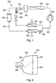
- An air conditioning system 210 comprises a refrigerant circuit 212, in which a compressor 214, a refrigerant condenser 216, a refrigerant collector 218, an expansion valve 220 and an evaporator 222 via Refrigerant lines 224, 226, 228, 230 are interconnected.
- a second one Evaporator 232 integrated in the refrigerant circuit 212, of which Refrigerant line 226 branches off a refrigerant line 234, which after the first evaporator 222 opens into the refrigerant line 230.
- an expansion device 236 and a shut-off valve 238 arranged in the refrigerant line 234. Via the shut-off valve 238 the refrigerant flow through the second evaporator 232 may be blocked become.
- a shut-off valve 240 after the first evaporator 222 provided so that the refrigerant flow through the first Evaporator 222 can be shut off.
- the first evaporator 222 can be shown in a manner not shown in FIG be constructed in a known manner.
- it can be one Activate flat tube evaporators in which the refrigerant side is connected in parallel Flat tubes extend between two manifolds and between the Flat tubes of heat-dissipating corrugated fins are provided.
- Such a Evaporator is known for example from DE 197 29 497 A1.
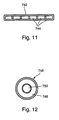
- the second evaporator 232 can be similar to the first evaporator 222 be constructed, but this evaporator also contains an Cold storage medium, for example in the individual tubes of the Evaporator can be included. These tubes can, for example, as Multi-channel flat tubes 742 can be designed according to FIG. 11, some of them the channels 744 the cold storage medium can be stored and in the other of the channels 744 the refrigerant flows. In an alternative The evaporator tubes 746 can also be embodied as coaxial tubes be formed, for example in the outer tube 748 Cold storage medium can be stored and in the inner tube 750 the refrigerant can flow, see Figure 12
- the cold storage medium may be embodied in a tube 260 or Container between an evaporator tube 262 and a heat dissipating Rib 264 may be incorporated into the evaporator.
- the second evaporator 232 can thus have cooling capacity via the Store cold storage medium so that this evaporator in the following Storage evaporator is called and an integration of cold storage and forms evaporator.
- a cold storage medium for example Decanol or tetradecane can be used.
- the cold storage medium should advantageously have a phase change at approx. 3 ° C to 10 ° C, preferably 3 ° C to 5 ° C.
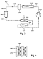
- FIG. 2 shows how the two evaporators 222 and 232 in one Air conditioner could be used to cool the air.
- the Evaporators 222 and 232 are in an air duct housing 252 of the Air conditioner 254 arranged in a known manner.
- Such air conditioners are usually located in the instrument panel of the motor vehicle. about a blower, not shown, can blow air in the direction of arrow 256 the evaporators 222 and 232 are promoted.
- the air side behind the Evaporators subsequent part of the air conditioner 254, which is usually a radiator and various air flaps and air ducts to the Individual air outlets are arranged in Fig. 2 is no further shown.
- An airflow control element is on the air side in front of the evaporators 222 and 232 258 arranged such that in one end position of the Air flow control element 258 the air through the first evaporator 222 is guided and in the other end position (dashed line in Fig. 2) Air is passed through the second evaporator 232.
- the evaporators 222 or 232 not flowed through by the air Airflow control element 258 blocked.
- the air passed through the first evaporator 222 and the second evaporator is 232 blocked on the air side.
- the second evaporator 232 is from the refrigerant flows through and so the cold storage medium can freeze.
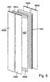
- a coolant circuit 312 in which identical or equivalent components with reference numbers increased by 100 are provided in an air conditioning system 310 two evaporators 322 and 332 connected in series in a coolant circuit 312, so that the Coolant circuit 312 only a compressor 314, a refrigerant condenser 316, a refrigerant collector 318, an expansion valve 320 and has the first evaporator 322 and the second evaporator 332, which are connected to one another via refrigerant lines 324, 326, 328, 330 are.
- the second evaporator 332 is in the coolant circuit 312, which can store cold with the help of a cold storage medium downstream of the first evaporator 322.
- first evaporator 222 or 322 and a second evaporator 232 or 332 are provided.
- This second section can the cold storage medium like the storage evaporator 232 or 332 in its individual evaporator tubes or the other above Embodiments correspond.
- an air conditioning system in which in one only air conditioner that does not take up much more space than previously known air conditioning units, two evaporators 222 and 232 or 322 and 332 or an evaporator with two sections is arranged with the mentioned properties, so with this air conditioner both during driving as well as when the engine is temporarily switched off in idle stop mode cooling and thus air conditioning of the air is possible.
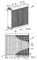
- FIG. 5 shows an arrangement of components of an evaporator, such as for example a flat tube evaporator.
- the flat tubes 462a to 462d are arranged in pairs in the exemplary embodiment, so that two Flat tubes 462a and 462b and also the flat tubes 462c and 462d each form a row, viewed in the direction of air flow. It can take place of the two flat tubes or other refrigerant tubes, but only one Flat tube or refrigerant tube per row, viewed in the direction of air flow, be provided or a plurality of flat tubes or Refrigerant pipes.
- the flat tubes expediently have a large number of individual channels 463 through which the refrigerant during operation of the Evaporator flows.
- the refrigerant tubes or flat tubes are on theirs Ends each connected to manifold sections and the channels 463 are in fluid communication with these header sections.
- At least one is advantageously between two rows of flat tubes Storage 460 arranged for a cold storage medium. It can be advantageous be there when the at least one memory is essentially the same Height and depth, like the refrigerant pipes used per row or like the evaporator itself. In another embodiment But it can also be useful if the memory in depth and / or height has a lesser or greater extent, in Comparison to the refrigerant pipes or the evaporator itself.
- this has at least one memory 460 on one side abuts or with one or more flat tubes 462a, 462b at least one flat tube is connected in one piece or advantageously with this at least one flat tube is formed in one piece.
- the memory can have essentially the same extent as the Flat tubes or essentially the expansion of the evaporator in the Have depth.
- the memory is off a flat tube formed at both ends 460a and 460b is closed. This closing can be done, for example, by a Folding or other method, such as by soldering or using a closure, such as a plug.
- heat dissipating rib 464 may be provided. It is useful if this rib 464 on one side of the flat tube between the flat tube and Storage is arranged.
- FIG. 6 shows an evaporator, such as a flat tube evaporator, 500 in a three-dimensional view and FIG. 7 shows an evaporator in FIG a two-dimensional view.
- the vaporizer, or also Storage evaporator, 500 has a series of flat tubes, Storage and ribs, which are arranged according to Figure 5.
- the evaporator has header sections 501 to 506, each with at least part of the flat tubes as refrigerant lines in Are in fluid communication.
- the refrigerant flows in the area of the Inlet opening 510 in the evaporator 500 and in the area of Inlet opening 511 out again.
- the refrigerant comes through the opening 510 into the manifold section 501, from there passes through the Refrigerant channels in flat tubes in the header tube section 502 and from there through refrigerant channels in flat tubes in the header section 503. From there, the refrigerant enters through at least one connection 512 the header pipe section 504. From there, the refrigerant passes Channels in flat tubes in the header tube section 505 um through channels to get back into the header pipe section 506. Then that occurs Refrigerant at opening 511 again. Between Header sections 501 and 503 and 504 and 506 are partitions 514 provided that separate the individual areas from each other.
- the Flat tubes of the evaporator 500 are designated 562. Between Rows 560 and fins 564 are arranged in rows of flat tubes. Not all ribs are drawn in and partially for better illustration the ribs are only partially shown.
- the flat tubes or refrigerant tubes one Have extension a transverse to the air flow direction, which is in the range of approx. 1mm to 5mm, preferably from 1.5 mm to 3mm. Furthermore it is advantageous if the extent b of the memory transverse to Air flow direction in the range of 1mm to 10mm, preferably from 1.5 mm to 6 mm. It is also expedient if the extension c Ribs across the air flow through the evaporator in the range of 3 mm up to 12mm, preferably from 4mm to 10mm. It is also advantageous if the ratio of the width of the memory to the width of the Refrigerant pipes in the range of 0.25 to 2, preferably in the range of 0.5 up to 1.5.
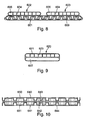
- FIG. 8 shows a section through a memory 601 for Cold storage medium and two flat tubes 602, 603 connected to the storage 601 are connected.
- the flat tubes are, for example, as extruded Flat tubes are formed and have a plurality of channels 605 which each have a fluid connection between the end regions of the Ensure flat tube.
- the refrigerant channels 605 are, for example separated from one another by webs 604.
- the channels 605 are for example rectangular, polygonal, such as triangular or pentagonal, oval or round in cross section.
- the flat tubes 602 and 603 are attached to the memory 601, such as integrally formed.
- the two flat tubes also be connected to a flat tube or instead of two flat tubes one or more flat tubes can also be used.
- a plurality of memories or storage tubes can be used side by side.
- Memory 601 also shows in FIG its interior a mechanical support 609, by a appropriately designed support element, such as support plate, that can be inserted into the storage interior. This serves the mechanical reinforcement or support. It is advantageous if this Support element through deep-drawn areas or angled areas are reinforced.
- FIG. 9 shows an exemplary embodiment of a memory with a flat tube, which are formed in one piece.
- the memory 622 is with the Flat tube 620 made in one piece.
- the flat tube part is with channels 621 formed and these are separated from one another by the webs 623.
- the Storage 622 thus forms part of a double tube.
- the memory as a chamber for the storage medium can, for example, by a Sealing plugs are closed.
- FIG. 10 shows a further advantageous embodiment of a Storage evaporator component in disc construction.
- the channels for that Refrigerant and the chamber for the storage medium are each through a disc 640 and possibly an intermediate disc 642 or through disk 641 and washer 642 are formed.
- a spatial area which can be used either as channels or as a chamber.
- webs or ribs or knobs or bowls can also be formed, which serve the reinforcement or the support.
- the individual components are connected in such a way that the gaps as Refrigerant channels 650 and as storage volume 651 fluid-tight Are completed.
- the channels can then be connected to the Refrigerant circuit must be connected or the chamber with the Cold storage agents are filled.
- the construction of an evaporator in Disc design can be advantageous for some applications.
- the Disc-type refrigerant ducts therefore also provide a refrigerant pipe in the sense of the present description, which by the structure and is characterized by the use of at least individual disks, whereby at least one refrigerant channel through at least two disks is produced.
- the cold storage of the evaporator or heat exchanger can each by means of at least one connecting line be connected / connectable, via which they can also be filled, for example and / or can be vented. At least individual memories can also be used a storage container, such as storage tank, are connected so that the Storage medium from this storage tank into the storage can be filled. The heat exchanger can then operate Storage container closed or opened again and if necessary be lockable again.
- a Cold storage medium takes place in such a way that the amount of Medium is sufficient to provide the necessary cooling capacity for a period of approx. 30 to 120 seconds, preferably also from about 60 seconds to ensure the compressor drive is switched off.
- This corresponds approximately to decanol or tetradecane as a cold storage medium a quantity of approx. 200 ml used, approx. 500 ml to approx. 1000 ml.
Landscapes
- Engineering & Computer Science (AREA)
- Physics & Mathematics (AREA)
- Thermal Sciences (AREA)
- Mechanical Engineering (AREA)
- Chemical & Material Sciences (AREA)
- General Engineering & Computer Science (AREA)
- Chemical Kinetics & Catalysis (AREA)
- Combustion & Propulsion (AREA)
- Materials Engineering (AREA)
- Organic Chemistry (AREA)
- Air-Conditioning For Vehicles (AREA)
- Sorption Type Refrigeration Machines (AREA)
- Motor Or Generator Cooling System (AREA)
- Heat-Exchange Devices With Radiators And Conduit Assemblies (AREA)
Priority Applications (1)
| Application Number | Priority Date | Filing Date | Title |
|---|---|---|---|
| EP06020366A EP1733906B1 (fr) | 2001-01-05 | 2001-11-20 | Dispositif de climatisation pour véhicule automobile |
Applications Claiming Priority (8)
| Application Number | Priority Date | Filing Date | Title |
|---|---|---|---|
| DE10100252 | 2001-01-05 | ||
| DE10100252 | 2001-01-05 | ||
| DE10145658 | 2001-09-15 | ||
| DE10145658 | 2001-09-15 | ||
| DE20115273U | 2001-09-15 | ||
| DE20115273U DE20115273U1 (de) | 2001-01-05 | 2001-09-15 | Klimaanlage für ein Kraftfahrzeug |
| DE10150896 | 2001-10-18 | ||
| DE10150896 | 2001-10-18 |
Related Child Applications (1)
| Application Number | Title | Priority Date | Filing Date |
|---|---|---|---|
| EP06020366A Division EP1733906B1 (fr) | 2001-01-05 | 2001-11-20 | Dispositif de climatisation pour véhicule automobile |
Publications (3)
| Publication Number | Publication Date |
|---|---|
| EP1221389A2 true EP1221389A2 (fr) | 2002-07-10 |
| EP1221389A3 EP1221389A3 (fr) | 2004-03-03 |
| EP1221389B1 EP1221389B1 (fr) | 2006-11-08 |
Family
ID=27437919
Family Applications (2)
| Application Number | Title | Priority Date | Filing Date |
|---|---|---|---|
| EP01127613A Expired - Lifetime EP1221390B1 (fr) | 2001-01-05 | 2001-11-20 | Dispositif de climatisation pour véhicule automobile |
| EP01127612A Expired - Lifetime EP1221389B1 (fr) | 2001-01-05 | 2001-11-20 | Dispositif de climatisation pour véhicule automobile |
Family Applications Before (1)
| Application Number | Title | Priority Date | Filing Date |
|---|---|---|---|
| EP01127613A Expired - Lifetime EP1221390B1 (fr) | 2001-01-05 | 2001-11-20 | Dispositif de climatisation pour véhicule automobile |
Country Status (5)
| Country | Link |
|---|---|
| US (3) | US6691527B2 (fr) |
| EP (2) | EP1221390B1 (fr) |
| JP (2) | JP4043776B2 (fr) |
| AT (1) | ATE318726T1 (fr) |
| DE (4) | DE10156944A1 (fr) |
Cited By (15)
| Publication number | Priority date | Publication date | Assignee | Title |
|---|---|---|---|---|
| EP1407905A1 (fr) * | 2002-10-10 | 2004-04-14 | Behr GmbH & Co. | Climatisation pour véhicule et procédé correspondant |
| WO2004033236A1 (fr) * | 2002-09-12 | 2004-04-22 | Behr Gmbh & Co. | Procede d'exploitation d'un evaporateur et dispositif approprie |
| FR2847973A1 (fr) * | 2002-11-29 | 2004-06-04 | Valeo Climatisation | Echangeur de chaleur a inertie thermique pour circuit de fluide caloporteur, notamment de vehicule automobile. |
| FR2861166A1 (fr) * | 2003-10-21 | 2005-04-22 | Valeo Climatisation | Echangeur de chaleur utilisant un fluide d'accumulation |
| DE102004035818A1 (de) * | 2004-07-23 | 2006-03-16 | Valeo Klimasysteme Gmbh | Wärmetauscher mit Latentspeicher |
| WO2006029720A1 (fr) * | 2004-09-14 | 2006-03-23 | Behr Gmbh & Co. Kg | Echangeur thermique pour vehicules a moteur |
| FR2878614A1 (fr) * | 2004-11-30 | 2006-06-02 | Valeo Climatisation Sa | Echangeur de chaleur avec accumulateur thermique |
| FR2878613A1 (fr) * | 2004-11-30 | 2006-06-02 | Valeo Climatisation Sa | Dispositif d'echange thermique a accumulateur thermique |
| WO2006059005A1 (fr) * | 2004-11-30 | 2006-06-08 | Valeo Systemes Thermiques | Echangeur de chaleur avec accumulateur thermique |
| DE102010056414A1 (de) | 2010-12-23 | 2012-06-28 | Volkswagen Ag | Klimaanlage mit Kompressions- und Sorptionskälteanlagenkreislauf |
| WO2013098277A1 (fr) * | 2011-12-30 | 2013-07-04 | Behr Gmbh & Co. Kg | Module pour transmetteur de chaleur, cœur de transmetteur de chaleur et transmetteur de chaleur |
| CN106196696B (zh) * | 2016-07-20 | 2018-07-31 | 广东省现代农业装备研究所 | 一种制冷蓄能低温热泵主机系统及其控制方法 |
| CN109398031A (zh) * | 2018-11-15 | 2019-03-01 | 三江瓦力特特种车辆有限公司 | 一种一拖二车载空调电路 |
| CN110329039A (zh) * | 2019-08-13 | 2019-10-15 | 安徽江淮汽车集团股份有限公司 | 汽车热管理系统及方法 |
| CN111319549A (zh) * | 2020-02-28 | 2020-06-23 | 上海中车通达智慧物流有限公司 | 一种移动充冷机及包括该移动充冷机的冷藏、冷冻车 |
Families Citing this family (167)
| Publication number | Priority date | Publication date | Assignee | Title |
|---|---|---|---|---|
| WO2003014634A1 (fr) | 2001-08-07 | 2003-02-20 | Bsst Llc | Appareil thermoelectrique pour environnement personnel |
| FR2836421B1 (fr) * | 2002-02-28 | 2009-11-27 | Denso Corp | Climatiseur pour vehicule avec unite de stockage du froid |
| JP3899993B2 (ja) * | 2002-04-19 | 2007-03-28 | 株式会社デンソー | 車両用空調装置 |
| DE10247083A1 (de) * | 2002-10-09 | 2004-04-22 | Behr Gmbh & Co. | Klimaanlage |
| DE10247262A1 (de) | 2002-10-10 | 2004-04-22 | Behr Gmbh & Co. | Verfahren zur Verdampfungstemperaturregelung bei einer Klimaanlage |
| DE10247268A1 (de) * | 2002-10-10 | 2004-05-13 | Behr Gmbh & Co. | Kältemittelverdampfer |
| WO2004035334A1 (fr) | 2002-10-10 | 2004-04-29 | Behr Gmbh & Co. | Systeme de climatisation pour vehicule et procede associe pour le faire fonctionner |
| DE10247263A1 (de) * | 2002-10-10 | 2004-04-22 | Behr Gmbh & Co. | Klimaanlage mit Strömungshomogenisierung |
| DE10248773B4 (de) * | 2002-10-18 | 2004-11-25 | Webasto Thermosysteme International Gmbh | Stop-And-Go-Klimatisierung |
| DE10251166A1 (de) * | 2002-10-31 | 2004-05-13 | Behr Gmbh & Co. | Vorrichtung zur Regelung der Luftzufuhr, insbesondere zu einem Verdampfer mit Speicherfunktion eines Kraftfahrzeuges |
| DE10258618B3 (de) * | 2002-12-16 | 2004-06-24 | Daimlerchrysler Ag | Klimaanlage, insbesondere für Kraftfahrzeuge |
| DE10259040A1 (de) * | 2002-12-17 | 2004-07-08 | Webasto Thermosysteme International Gmbh | Stop-And-Go-Klimatisierung |
| JP2004224133A (ja) * | 2003-01-21 | 2004-08-12 | Kobelco Contstruction Machinery Ltd | 建設機械の動力制御装置 |
| DE10306048B4 (de) * | 2003-02-13 | 2007-09-27 | Webasto Ag | Klimatisierungssystem für ein Kraftfahrzeug |
| DE10308254A1 (de) * | 2003-02-25 | 2004-09-02 | Behr Gmbh & Co. Kg | Klimaanlage für ein Fahrzeug und zugehöriges Betriebsverfahren |
| DE502004005798D1 (de) * | 2003-03-04 | 2008-02-14 | Imtech Deutschland Gmbh & Co K | Raumtemperierungseinrichtung |
| DE10318655C5 (de) * | 2003-04-24 | 2008-07-10 | Webasto Ag | Klimatisierungssystem für ein Kraftfahrzeug und Verfahren zum Betreiben desselben |
| DE10338824A1 (de) * | 2003-08-21 | 2005-03-24 | Behr Gmbh & Co. Kg | Klimaanlage |
| ATE426521T1 (de) | 2003-09-10 | 2009-04-15 | Behr Gmbh & Co Kg | Kaltemittel-kreislauf fur eine kraftfahrzeug- klimaanlage, kraftfahrzeug-klimaanlage und verfahren zum betreiben einer solchen |
| DE10344554A1 (de) | 2003-09-24 | 2005-05-04 | Behr Gmbh & Co Kg | Klimaanlage und Verfahren zum Regeln einer Kraftfahrzeug-Klimaanlage und eines Kraftfahrzeug-Motors |
| EP1527916A1 (fr) * | 2003-10-27 | 2005-05-04 | Behr GmbH & Co. KG | Système de chauffage pour véhicule avec source de chaleur auxiliaire |
| DE10355397A1 (de) * | 2003-11-25 | 2005-06-30 | Behr Gmbh & Co. Kg | Kraftfahrzeug-Klimaanlage mit Standklimatisierung |
| US7380586B2 (en) * | 2004-05-10 | 2008-06-03 | Bsst Llc | Climate control system for hybrid vehicles using thermoelectric devices |
| DE102004030074A1 (de) | 2004-06-23 | 2006-01-12 | Behr Gmbh & Co. Kg | Verfahren zum Betreiben einer Klimatisierungseinrichtung für Fahrzeuge |
| JP2006044424A (ja) * | 2004-08-03 | 2006-02-16 | Sanden Corp | 車両用空調装置 |
| US20060059933A1 (en) * | 2004-09-21 | 2006-03-23 | W.E.T. Automotive Systems Ag | Heating, cooling and ventilation system for a vehicle seat |
| DE102004052979A1 (de) * | 2004-10-29 | 2006-05-04 | Behr Gmbh & Co. Kg | Klimaanlage mit Kältespeicher |
| DE502005007311D1 (de) * | 2004-10-29 | 2009-07-02 | Behr Gmbh & Co Kg | Klimaanlage mit Kältespeicher |
| DE102004055343A1 (de) * | 2004-11-16 | 2006-05-18 | Behr Gmbh & Co. Kg | Klimaanlage mit Kältespeicher |
| DE102004055341A1 (de) * | 2004-11-16 | 2006-05-18 | Behr Gmbh & Co. Kg | Wärmetauscher mit Kältespeicherelement |
| DE102004055340A1 (de) * | 2004-11-16 | 2006-05-18 | Behr Gmbh & Co. Kg | Klimaanlage mit Kältespeicher |
| DE102004055339A1 (de) * | 2004-11-16 | 2006-05-18 | Behr Gmbh & Co. Kg | Klimaanlage mit Kältespeicher |
| DE102004060000B3 (de) * | 2004-12-14 | 2006-04-20 | Bayerische Motoren Werke Ag | Klimaanlage für Kraftfahrzeuge |
| US7743614B2 (en) * | 2005-04-08 | 2010-06-29 | Bsst Llc | Thermoelectric-based heating and cooling system |
| US7275394B2 (en) * | 2005-04-22 | 2007-10-02 | Visteon Global Technologies, Inc. | Heat exchanger having a distributer plate |
| DE102005021396A1 (de) * | 2005-05-04 | 2006-11-09 | Behr Gmbh & Co. Kg | Vorrichtung zur Luftkonditionierung für ein Kraftfahrzeug |
| JP4508006B2 (ja) * | 2005-06-24 | 2010-07-21 | 株式会社デンソー | 車両用冷凍サイクル装置 |
| US7891211B2 (en) * | 2005-06-24 | 2011-02-22 | Denso Corporation | Cold storage tank unit and refrigeration cycle apparatus using the same |
| US8783397B2 (en) * | 2005-07-19 | 2014-07-22 | Bsst Llc | Energy management system for a hybrid-electric vehicle |
| DE102005035017A1 (de) * | 2005-07-27 | 2007-02-01 | Behr Gmbh & Co. Kg | Wärmeübertrager zur Kühlung von Ladeluft |
| KR101151627B1 (ko) | 2005-12-26 | 2012-06-08 | 한라공조주식회사 | 축냉 열교환기 |
| KR101170610B1 (ko) * | 2006-01-04 | 2012-08-02 | 한라공조주식회사 | 축냉 열교환기 |
| DE102006001919A1 (de) * | 2006-01-14 | 2007-07-19 | Volkswagen Ag | Kältemittel-Kreislauf für eine Klimaanlage in einem Kraftfahrzeug |
| JP5264507B2 (ja) * | 2006-02-10 | 2013-08-14 | ベール ゲーエムベーハー ウント コー カーゲー | 蓄冷器を有する熱交換器 |
| DE102006028017A1 (de) * | 2006-02-10 | 2007-08-16 | Behr Gmbh & Co. Kg | Wärmeübertrager, insbesondere mit Kältespeicher |
| DE102006011327A1 (de) | 2006-03-09 | 2007-09-13 | Behr Gmbh & Co. Kg | Wärmeübertrager mit Kältespeicher |
| US7870745B2 (en) | 2006-03-16 | 2011-01-18 | Bsst Llc | Thermoelectric device efficiency enhancement using dynamic feedback |
| KR101224516B1 (ko) * | 2006-05-17 | 2013-01-22 | 한라공조주식회사 | 축냉부를 구비한 증발기 |
| US7779639B2 (en) * | 2006-08-02 | 2010-08-24 | Bsst Llc | HVAC system for hybrid vehicles using thermoelectric devices |
| US20100155018A1 (en) | 2008-12-19 | 2010-06-24 | Lakhi Nandlal Goenka | Hvac system for a hybrid vehicle |
| DE102006042789A1 (de) * | 2006-09-08 | 2008-03-27 | Behr Gmbh & Co. Kg | Klimaanalge mit Kältespeicher und Verfahren zum Betreiben einer solchen |
| JP4324187B2 (ja) * | 2006-10-25 | 2009-09-02 | トヨタ自動車株式会社 | 蓄熱装置 |
| DE102006051865A1 (de) * | 2006-10-31 | 2008-05-08 | Behr Gmbh & Co. Kg | Verfahren und Vorrichtung zum Befüllen eines Kältespeichers von einem Wärmeübertrager |
| WO2008148042A2 (fr) * | 2007-05-25 | 2008-12-04 | Bsst Llc | Système et procédé pour le chauffage et le refroidissement thermoélectrique distribués |
| DE102007036303A1 (de) * | 2007-07-31 | 2009-02-05 | Behr Gmbh & Co. Kg | Speicher zum Speichern eines Kältepotenzials, Kreislauf zur Motoraufladung, Klimaanlage und System aus Kreislauf und Klimaanlage sowie Verfahren zum Kühlen eines zur Motoraufladung vorgesehenen im wesentlichen gasförmigen Fluids |
| JP2009154804A (ja) * | 2007-12-27 | 2009-07-16 | Calsonic Kansei Corp | 車両用空調装置 |
| US20090188266A1 (en) | 2008-01-29 | 2009-07-30 | Stephen Think Hung | Heating, ventilating, and air conditioning system having a thermal energy exchanger |
| US20090191804A1 (en) * | 2008-01-29 | 2009-07-30 | Lakhi Nandlal Goenka | Heating, ventilating, and air conditioning system having a thermal energy exchanger |
| US20090211732A1 (en) | 2008-02-21 | 2009-08-27 | Lakhi Nandlal Goenka | Thermal energy exchanger for a heating, ventilating, and air conditioning system |
| DE102008020351A1 (de) * | 2008-04-23 | 2009-10-29 | Valeo Klimasysteme Gmbh | Verfahren zum Betreiben einer Klimatisierungsanlage für ein Kraftfahrzeug |
| US8701422B2 (en) | 2008-06-03 | 2014-04-22 | Bsst Llc | Thermoelectric heat pump |
| EP2144029A1 (fr) | 2008-07-11 | 2010-01-13 | Behr France Hambach S.A.R.L. | Echangeur thermique, en particulier d'un véhicule automobile, destiné au refroidissement d'un liquide de refroidissement et procédé de refroidissement d'un liquide de refroidissement |
| JP5444782B2 (ja) * | 2008-09-12 | 2014-03-19 | 株式会社デンソー | 蓄冷熱交換器 |
| JP5274175B2 (ja) * | 2008-09-19 | 2013-08-28 | 株式会社ケーヒン・サーマル・テクノロジー | 蓄冷熱交換器 |
| US20110172880A1 (en) * | 2008-09-26 | 2011-07-14 | Pioneer Corporation | Air conditioning control device and air conditioning control method |
| WO2010044417A1 (fr) * | 2008-10-14 | 2010-04-22 | 株式会社セルシード | Substrat de culture cellulaire sensible à la température et son procédé de production |
| EP2177255B8 (fr) | 2008-10-15 | 2012-08-29 | Kaeser Kompressoren AG | Dispositif de séchage à froid |
| US9555686B2 (en) | 2008-10-23 | 2017-01-31 | Gentherm Incorporated | Temperature control systems with thermoelectric devices |
| EP2946953A1 (fr) | 2008-10-23 | 2015-11-25 | Bsst Llc | Système cvc multimode à dispositif thermoélectrique |
| FR2937718B1 (fr) * | 2008-10-23 | 2013-04-26 | Valeo Systemes Thermiques | Echangeur de chaleur apte a refroidir un fluide refrigerant qui circule a l'interieur dudit echangeur et comportant au moins un materiau a changement de phase |
| US9447994B2 (en) | 2008-10-23 | 2016-09-20 | Gentherm Incorporated | Temperature control systems with thermoelectric devices |
| JP5276954B2 (ja) * | 2008-11-10 | 2013-08-28 | 株式会社ケーヒン・サーマル・テクノロジー | 蓄冷機能付きエバポレータ |
| KR101527888B1 (ko) * | 2008-11-21 | 2015-06-10 | 한라비스테온공조 주식회사 | 축냉 열교환기 |
| JP5525726B2 (ja) | 2008-12-26 | 2014-06-18 | 株式会社ケーヒン・サーマル・テクノロジー | 蓄冷機能付きエバポレータ |
| FR2941041B1 (fr) * | 2009-01-12 | 2010-12-31 | Valeo Systemes Thermiques | Echangeur de chaleur a accumulateur thermique |
| FR2941522B1 (fr) * | 2009-01-27 | 2012-08-31 | Valeo Systemes Thermiques | Echangeur de chaleur pour deux fluides, en particulier evaporateur de stockage pour dispositif de climatisation |
| JP5486837B2 (ja) * | 2009-05-08 | 2014-05-07 | 株式会社ケーヒン・サーマル・テクノロジー | 蓄冷機能付きエバポレータ |
| US20100223949A1 (en) * | 2009-03-06 | 2010-09-09 | Showa Denko K.K. | Evaporator with cool storage function |
| JP5315094B2 (ja) * | 2009-03-06 | 2013-10-16 | 株式会社ケーヒン・サーマル・テクノロジー | 蓄冷機能付きエバポレータ |
| FR2943775B1 (fr) * | 2009-03-24 | 2012-07-13 | Valeo Systemes Thermiques | Echangeur de stockage pourvu d'un materiau stockeur et boucle de climatisation ou circuit de refroidissement comprenant un tel echangeur. |
| KR101213564B1 (ko) * | 2009-03-26 | 2012-12-18 | 가부시키가이샤 덴소 | 냉기 저장형 열교환기 |
| JP5194241B2 (ja) * | 2009-03-31 | 2013-05-08 | 株式会社ケーヒン・サーマル・テクノロジー | 蓄冷機能付きエバポレータ |
| JP2010243066A (ja) * | 2009-04-07 | 2010-10-28 | Showa Denko Kk | 蓄冷熱交換器 |
| JP4858573B2 (ja) | 2009-05-18 | 2012-01-18 | 株式会社デンソー | エアコン制御装置 |
| CN104914896B (zh) | 2009-05-18 | 2017-06-13 | 詹思姆公司 | 带有热电装置的温度控制系统 |
| KR102112970B1 (ko) | 2009-05-18 | 2020-05-19 | 젠썸 인코포레이티드 | 배터리 열 관리 시스템 |
| FR2945859B1 (fr) * | 2009-05-19 | 2011-06-17 | Valeo Systemes Thermiques | Dispositif d'echange thermique contenant un materiau de stockage thermique |
| JP5574819B2 (ja) * | 2009-05-22 | 2014-08-20 | 株式会社ケーヒン・サーマル・テクノロジー | 蓄冷機能付きエバポレータ |
| JP5768844B2 (ja) * | 2009-06-05 | 2015-08-26 | 株式会社デンソー | 蓄冷熱交換器 |
| JP5408017B2 (ja) | 2009-06-05 | 2014-02-05 | 株式会社デンソー | 蓄冷熱交換器 |
| US9581369B2 (en) * | 2009-06-10 | 2017-02-28 | Mahle International Gmbh | Evaporator with phase change material |
| US9518768B2 (en) * | 2009-06-10 | 2016-12-13 | Mahle International Gmbh | Evaporator having a phase change material louvered clam shell housing |
| DE102009034303A1 (de) | 2009-07-21 | 2011-01-27 | Behr Gmbh & Co. Kg | Wärmeübertrager |
| JP5381626B2 (ja) * | 2009-11-06 | 2014-01-08 | 株式会社デンソー | 蓄冷熱交換器 |
| US8978412B2 (en) * | 2009-12-04 | 2015-03-17 | Halla Visteon Climate Control Corporation | Air conditioner for vehicles |
| JP2011133127A (ja) * | 2009-12-22 | 2011-07-07 | Showa Denko Kk | 蓄冷機能付きエバポレータ |
| JP5624761B2 (ja) * | 2009-12-25 | 2014-11-12 | 株式会社ケーヒン・サーマル・テクノロジー | 蓄冷機能付きエバポレータ |
| JP5574700B2 (ja) * | 2009-12-25 | 2014-08-20 | 株式会社ケーヒン・サーマル・テクノロジー | 蓄冷機能付きエバポレータ |
| JP5674388B2 (ja) * | 2009-12-25 | 2015-02-25 | 株式会社ケーヒン・サーマル・テクノロジー | 蓄冷機能付きエバポレータ |
| JP5525840B2 (ja) * | 2010-02-02 | 2014-06-18 | 株式会社ケーヒン・サーマル・テクノロジー | 蓄冷機能付きエバポレータ |
| US20120042687A1 (en) * | 2010-08-23 | 2012-02-23 | Showa Denko K.K. | Evaporator with cool storage function |
| JP2012126149A (ja) * | 2010-12-13 | 2012-07-05 | Showa Denko Kk | 蓄冷機能付きエバポレータ |
| JP2012102969A (ja) * | 2010-11-12 | 2012-05-31 | Showa Denko Kk | 蓄冷機能付きエバポレータ |
| JP5768480B2 (ja) * | 2011-05-10 | 2015-08-26 | 株式会社デンソー | 蓄冷熱交換器 |
| DE112012002935T5 (de) | 2011-07-11 | 2014-05-15 | Gentherm Inc. | Auf Thermoelektrik basierendes Wärmemanagement elektrischer Vorrichtungen |
| JP5868088B2 (ja) | 2011-09-15 | 2016-02-24 | 株式会社ケーヒン・サーマル・テクノロジー | 車両用空調装置のクーリングユニット |
| ES2584967T5 (es) * | 2011-09-15 | 2024-02-23 | Alstom Transp Tech | Procedimiento de refrigeración del aire y sistema de aire acondicionado para vehículos |
| US9109841B2 (en) | 2011-10-06 | 2015-08-18 | Halla Visteon Climate Control Corporation | Air to refrigerant heat exchanger with phase change material |
| JP2013088016A (ja) * | 2011-10-18 | 2013-05-13 | Keihin Thermal Technology Corp | 蓄冷機能付きエバポレータ |
| EP2769163B1 (fr) | 2011-10-19 | 2020-12-30 | Carrier Corporation | Echangeur de chaleur à ailettes en tube aplati et procédé de fabrication |
| US9285153B2 (en) | 2011-10-19 | 2016-03-15 | Thermo Fisher Scientific (Asheville) Llc | High performance refrigerator having passive sublimation defrost of evaporator |
| US9310121B2 (en) | 2011-10-19 | 2016-04-12 | Thermo Fisher Scientific (Asheville) Llc | High performance refrigerator having sacrificial evaporator |
| US9242530B2 (en) | 2011-10-28 | 2016-01-26 | Hanon Systems | Heat exchanger with phase change material manifolds |
| JP5983335B2 (ja) * | 2011-11-30 | 2016-08-31 | 株式会社デンソー | 熱交換器 |
| DE102011090159A1 (de) | 2011-12-30 | 2013-07-04 | Behr Gmbh & Co. Kg | Wärmeübertrager |
| KR101443645B1 (ko) * | 2012-02-07 | 2014-09-23 | 엘지전자 주식회사 | 전기자동차용 공기조화장치 |
| JP5898995B2 (ja) * | 2012-02-20 | 2016-04-06 | 株式会社ケーヒン・サーマル・テクノロジー | カーエアコン用蓄冷機能付きエバポレータの製造方法 |
| JP5796530B2 (ja) * | 2012-04-02 | 2015-10-21 | 株式会社デンソー | 蓄冷機能付きエバポレータの蓄冷ケース |
| TWI631033B (zh) * | 2012-06-19 | 2018-08-01 | 張福齡 | Vehicle idle speed stop and start and control method for displaying vehicle position |
| DE102012014242A1 (de) * | 2012-07-18 | 2014-01-23 | Valeo Klimasysteme Gmbh | Fahrzeugklimaanlage |
| DE102012213542A1 (de) * | 2012-08-01 | 2014-02-06 | Goselig UG | Kältespeichervorrichtung sowie Kühlanlagenanordnung |
| JP5910415B2 (ja) * | 2012-08-22 | 2016-04-27 | 株式会社デンソー | 蓄冷熱交換器 |
| FR2996630B1 (fr) * | 2012-10-09 | 2014-12-19 | Commissariat Energie Atomique | Procede de realisation d'un echangeur de chaleur contenant un materiau a changement de phase, echangeur obtenu et utilisations aux hautes temperatures. |
| JP6004906B2 (ja) * | 2012-11-15 | 2016-10-12 | 株式会社日本クライメイトシステムズ | 蓄冷機能付きエバポレータ |
| US9914339B2 (en) | 2013-01-30 | 2018-03-13 | Hanon Systems | Supplemental thermal storage |
| US9682608B2 (en) | 2013-01-30 | 2017-06-20 | Hanon Systems | Supplemental heating and cooling sources for a heating, ventilation and air conditioning system |
| US10202019B2 (en) | 2013-01-30 | 2019-02-12 | Hanon Systems | HVAC blower |
| US20140208794A1 (en) * | 2013-01-30 | 2014-07-31 | Visteon Global Technologies, Inc. | Thermal energy exchanger with heat pipe |
| US20140209278A1 (en) * | 2013-01-30 | 2014-07-31 | Visteon Global Technologies, Inc. | Thermal energy storage system with heat pump, reduced heater core, and integrated battery cooling and heating |
| US20140216684A1 (en) * | 2013-02-01 | 2014-08-07 | Visteon Global Technologies, Inc. | Heating, ventilating, and air conditioning system with an exhaust gas thermal energy exchanger |
| JP5501494B2 (ja) * | 2013-03-15 | 2014-05-21 | 株式会社ケーヒン・サーマル・テクノロジー | 蓄冷機能付きエバポレータ |
| JP5501493B2 (ja) * | 2013-03-15 | 2014-05-21 | 株式会社ケーヒン・サーマル・テクノロジー | 蓄冷機能付きエバポレータ |
| FR3007514B1 (fr) * | 2013-06-20 | 2017-12-15 | Valeo Systemes Thermiques | Tube a reservoir de materiau a changement de phases pour faisceau d'echange de chaleur, notamment pour un evaporateur d'un circuit de climatisation d'un vehicule |
| JP5600796B2 (ja) * | 2013-11-07 | 2014-10-01 | 株式会社ケーヒン・サーマル・テクノロジー | 蓄冷機能付きエバポレータ |
| US20150198385A1 (en) * | 2014-01-13 | 2015-07-16 | Deere & Company | Cross Flow Heat Exchanger |
| US9789746B2 (en) * | 2014-03-25 | 2017-10-17 | Ford Global Technologies, Llc | Adsorption air-conditioning system |
| JP6217525B2 (ja) * | 2014-05-23 | 2017-10-25 | 株式会社デンソー | 熱交換器 |
| JP6410660B2 (ja) | 2014-06-17 | 2018-10-24 | 株式会社ケーヒン・サーマル・テクノロジー | 蓄冷機能付きエバポレータ |
| CN106662388B (zh) * | 2014-07-21 | 2019-09-06 | Lg电子株式会社 | 冰箱及其控制方法 |
| JP6337675B2 (ja) * | 2014-07-29 | 2018-06-06 | 株式会社デンソー | 蓄熱システム |
| US9643468B2 (en) | 2014-08-13 | 2017-05-09 | Fca Us Llc | Regenerative vehicle air conditioning system |
| US9821630B2 (en) | 2014-09-15 | 2017-11-21 | Hanon Systems | Modular air conditioning system |
| FR3025873B1 (fr) * | 2014-09-17 | 2016-12-23 | Valeo Systemes Thermiques | Evaporateur stockeur avec design plaques gaufrettes facilitant la congelation du pcm |
| DE102014219944A1 (de) * | 2014-10-01 | 2016-04-21 | Mahle International Gmbh | Aufgeladene Brennkraftmaschine |
| CN107249910B (zh) | 2014-12-19 | 2021-01-15 | 詹思姆公司 | 用于车辆区域的热调节系统和方法 |
| US10226984B2 (en) * | 2015-04-10 | 2019-03-12 | Ford Global Technologies, Llc | Air-conditioning system with vacuum enclosure |
| FR3035201B1 (fr) * | 2015-04-16 | 2017-05-05 | Valeo Systemes Thermiques | Tube a reservoir de materiau a changement de phase pour echangeur de chaleur. |
| JP6406116B2 (ja) | 2015-04-28 | 2018-10-17 | 株式会社デンソー | 車両用空調装置 |
| JP6623912B2 (ja) | 2015-04-30 | 2019-12-25 | 株式会社デンソー | 蒸発器 |
| US10436495B2 (en) * | 2015-05-01 | 2019-10-08 | Thermo King Corporation | Integrated thermal energy module within an air-cooled evaporator design |
| WO2016194656A1 (fr) * | 2015-05-29 | 2016-12-08 | カルソニックカンセイ株式会社 | Échangeur de chaleur |
| US10179498B2 (en) | 2015-05-30 | 2019-01-15 | Air International Inc. | Storage evaporator having phase change material for use in vehicle air conditioning system |
| JP6409836B2 (ja) | 2015-10-01 | 2018-10-24 | 株式会社デンソー | 蓄冷熱交換器 |
| WO2017065847A1 (fr) | 2015-10-14 | 2017-04-20 | Gentherm Incorporated | Systèmes et procédés de commande de conditionnement thermique de régions de véhicule |
| JP2017141978A (ja) * | 2016-02-08 | 2017-08-17 | 株式会社ケーヒン・サーマル・テクノロジー | 蓄冷機能付きエバポレータ |
| JP6597458B2 (ja) * | 2016-04-05 | 2019-10-30 | 株式会社デンソー | 冷媒蒸発器 |
| DE112017003449T5 (de) | 2016-07-08 | 2019-04-04 | Denso Corporation | Kaltspeicherwärmetauscher |
| US11530877B2 (en) * | 2016-08-01 | 2022-12-20 | Lockheed Martin Corporation | Heat exchange using phase change material |
| CN111315602A (zh) | 2017-11-10 | 2020-06-19 | 韦巴斯托股份公司 | 用于车辆的超低型廓hvac设备 |
| US11427051B2 (en) * | 2017-11-10 | 2022-08-30 | Webasto SE | Ultra-low profile HVAC apparatus for a vehicle |
| CN110879015A (zh) * | 2018-09-05 | 2020-03-13 | 广东美的白色家电技术创新中心有限公司 | 蓄能换热装置及空调设备 |
| CN121230238A (zh) | 2018-11-30 | 2025-12-30 | 金瑟姆股份公司 | 热电调节系统和方法 |
| DE102018222815A1 (de) * | 2018-12-21 | 2020-06-25 | Mahle International Gmbh | Aufnahmekasten für eine Wärmeübertrager |
| US11181323B2 (en) * | 2019-02-21 | 2021-11-23 | Qualcomm Incorporated | Heat-dissipating device with interfacial enhancements |
| JP7099392B2 (ja) * | 2019-04-03 | 2022-07-12 | トヨタ自動車株式会社 | 車載温調装置 |
| CN117128665A (zh) * | 2023-08-18 | 2023-11-28 | 浙江康盛科工贸有限公司 | 一种冰箱用蓄冷型节能蒸发器 |
| CN119687701A (zh) * | 2023-09-25 | 2025-03-25 | 浙江盾安热工科技有限公司 | 多介质微通道换热器 |
Citations (2)
| Publication number | Priority date | Publication date | Assignee | Title |
|---|---|---|---|---|
| DE19729497A1 (de) | 1997-07-10 | 1999-01-14 | Behr Gmbh & Co | Flachrohr-Wärmeübertrager |
| EP0995621A2 (fr) | 1998-10-23 | 2000-04-26 | Denso Corporation | Système de conditionnement d'air pour véhicule |
Family Cites Families (26)
| Publication number | Priority date | Publication date | Assignee | Title |
|---|---|---|---|---|
| US3128608A (en) * | 1962-01-11 | 1964-04-14 | Dole Refrigerating Co | Automotive air conditioning system |
| US4306613A (en) * | 1980-03-10 | 1981-12-22 | Christopher Nicholas S | Passive cooling system |
| US4412426A (en) * | 1980-12-22 | 1983-11-01 | Yuan Shao W | Wiser cooling system |
| US4354359A (en) * | 1981-01-05 | 1982-10-19 | Hall Roger W | Cold storage assembly |
| US4637222A (en) * | 1984-06-08 | 1987-01-20 | Nippondenso Co., Ltd. | Refrigerator for vehicle |
| JPS61159036A (ja) * | 1984-12-29 | 1986-07-18 | Takenaka Komuten Co Ltd | 蓄熱型熱交換素子及びそれを用いた冷暖房方法 |
| US4735064A (en) * | 1986-11-17 | 1988-04-05 | Fischer Harry C | Energy storage container and system |
| DE3704182A1 (de) | 1987-02-11 | 1988-08-25 | Forschungszentrum Fuer Kaeltet | Kuehlanlage |
| JP2536298B2 (ja) * | 1988-02-27 | 1996-09-18 | 日本電装株式会社 | 蓄冷装置 |
| US5277038A (en) * | 1992-08-28 | 1994-01-11 | Instatherm Company | Thermal storage system for a vehicle |
| DE4327866C1 (de) | 1993-08-19 | 1994-09-22 | Daimler Benz Ag | Einrichtung zur Klimatisierung des Fahrgastraums und zur Kühlung des Antriebssystems von Elektrofahrzeugen |
| FR2713320B1 (fr) * | 1993-12-02 | 1996-02-02 | Mc International | Procédé de commande et de dégivrage en continu d'un échangeur frigorifique et installation équipée d'un tel échangeur. |
| US6059016A (en) * | 1994-08-11 | 2000-05-09 | Store Heat And Produce Energy, Inc. | Thermal energy storage and delivery system |
| US5644929A (en) * | 1994-12-16 | 1997-07-08 | Nippondenso Co., Ltd. | Heat regenerating type cooling apparatus |
| FR2745894B1 (fr) * | 1996-03-08 | 1998-04-03 | Selnor | Echangeur de chaleur a accumulation pour appareil a generation de froid |
| JPH1053019A (ja) * | 1996-06-03 | 1998-02-24 | Denso Corp | 車両用空調装置 |
| US5871041A (en) * | 1996-09-25 | 1999-02-16 | Mid-America Capital Resources, Inc. | Thermal energy storage and delivery apparatus and vehicular systems incorporating same |
| DE19645178C2 (de) | 1996-11-02 | 1999-12-16 | Webasto Thermosysteme Gmbh | Vorrichtung zur Kühlung eines Fahrzeuginnenraumes |
| JPH10157449A (ja) * | 1996-11-28 | 1998-06-16 | Denso Corp | 冷凍サイクル装置 |
| US6079481A (en) * | 1997-01-23 | 2000-06-27 | Ail Research, Inc | Thermal storage system |
| DE19749793A1 (de) | 1997-11-11 | 1999-05-12 | Behr Gmbh & Co | Speicher thermischer Energie |
| DE19753601A1 (de) * | 1997-12-03 | 1999-06-10 | Behr Gmbh & Co | Kältespeicher, insbesondere für ein Kraftfahrzeug |
| DE19831256A1 (de) | 1998-07-11 | 2000-01-13 | Behr Gmbh & Co | Halterung für Wärmeübertrager, insbesondere für Kühler von Kraftfahrzeugen |
| DE19857121B4 (de) * | 1998-12-11 | 2017-06-01 | Mahle International Gmbh | Kältespeicher, insbesondere für die Klimatisierung eines Fahrzeuginnenraumes |
| DE19860057C5 (de) | 1998-12-23 | 2009-03-05 | Valeo Klimasysteme Gmbh | Klimaanlage für ein Fahrzeug mit einem Kältespeicher |
| DE10124757A1 (de) * | 2000-05-26 | 2001-11-29 | Denso Corp | Fahrzeugklimaanlage mit Kältespeicher |
-
2001
- 2001-11-20 EP EP01127613A patent/EP1221390B1/fr not_active Expired - Lifetime
- 2001-11-20 DE DE10156944A patent/DE10156944A1/de not_active Withdrawn
- 2001-11-20 AT AT01127613T patent/ATE318726T1/de not_active IP Right Cessation
- 2001-11-20 EP EP01127612A patent/EP1221389B1/fr not_active Expired - Lifetime
- 2001-11-20 DE DE2001156882 patent/DE10156882A1/de not_active Withdrawn
- 2001-11-20 DE DE50109051T patent/DE50109051D1/de not_active Expired - Lifetime
- 2001-11-20 DE DE50111403T patent/DE50111403D1/de not_active Expired - Lifetime
- 2001-12-14 JP JP2001380965A patent/JP4043776B2/ja not_active Expired - Fee Related
- 2001-12-14 JP JP2001381383A patent/JP4343472B2/ja not_active Expired - Fee Related
- 2001-12-21 US US10/024,627 patent/US6691527B2/en not_active Expired - Fee Related
- 2001-12-21 US US10/024,344 patent/US6568205B2/en not_active Expired - Lifetime
-
2003
- 2003-11-12 US US10/704,557 patent/US6854286B2/en not_active Expired - Lifetime
Patent Citations (2)
| Publication number | Priority date | Publication date | Assignee | Title |
|---|---|---|---|---|
| DE19729497A1 (de) | 1997-07-10 | 1999-01-14 | Behr Gmbh & Co | Flachrohr-Wärmeübertrager |
| EP0995621A2 (fr) | 1998-10-23 | 2000-04-26 | Denso Corporation | Système de conditionnement d'air pour véhicule |
Cited By (20)
| Publication number | Priority date | Publication date | Assignee | Title |
|---|---|---|---|---|
| WO2004033236A1 (fr) * | 2002-09-12 | 2004-04-22 | Behr Gmbh & Co. | Procede d'exploitation d'un evaporateur et dispositif approprie |
| EP1407905A1 (fr) * | 2002-10-10 | 2004-04-14 | Behr GmbH & Co. | Climatisation pour véhicule et procédé correspondant |
| US7156156B2 (en) | 2002-11-29 | 2007-01-02 | Valeo Climatisation | Heat exchanger with thermal inertia for a heat transfer fluid circuit, particularly of a motor vehicle |
| FR2847973A1 (fr) * | 2002-11-29 | 2004-06-04 | Valeo Climatisation | Echangeur de chaleur a inertie thermique pour circuit de fluide caloporteur, notamment de vehicule automobile. |
| EP1424531A3 (fr) * | 2002-11-29 | 2005-09-14 | Valeo Climatisation | Echangeur de chaleur à inertie thermique pour circuit de fluide caloporteur, notamment de véhicule automobile |
| FR2861166A1 (fr) * | 2003-10-21 | 2005-04-22 | Valeo Climatisation | Echangeur de chaleur utilisant un fluide d'accumulation |
| US7891412B2 (en) | 2003-10-21 | 2011-02-22 | Valeo Systemes Thermiques | Heat exchanger using a storage fluid |
| DE102004035818A1 (de) * | 2004-07-23 | 2006-03-16 | Valeo Klimasysteme Gmbh | Wärmetauscher mit Latentspeicher |
| WO2006029720A1 (fr) * | 2004-09-14 | 2006-03-23 | Behr Gmbh & Co. Kg | Echangeur thermique pour vehicules a moteur |
| FR2878613A1 (fr) * | 2004-11-30 | 2006-06-02 | Valeo Climatisation Sa | Dispositif d'echange thermique a accumulateur thermique |
| WO2006059005A1 (fr) * | 2004-11-30 | 2006-06-08 | Valeo Systemes Thermiques | Echangeur de chaleur avec accumulateur thermique |
| FR2878614A1 (fr) * | 2004-11-30 | 2006-06-02 | Valeo Climatisation Sa | Echangeur de chaleur avec accumulateur thermique |
| US8122943B2 (en) | 2004-11-30 | 2012-02-28 | Valeo Climatisation | Heat exchanger with heat storage |
| DE102010056414A1 (de) | 2010-12-23 | 2012-06-28 | Volkswagen Ag | Klimaanlage mit Kompressions- und Sorptionskälteanlagenkreislauf |
| WO2013098277A1 (fr) * | 2011-12-30 | 2013-07-04 | Behr Gmbh & Co. Kg | Module pour transmetteur de chaleur, cœur de transmetteur de chaleur et transmetteur de chaleur |
| CN106196696B (zh) * | 2016-07-20 | 2018-07-31 | 广东省现代农业装备研究所 | 一种制冷蓄能低温热泵主机系统及其控制方法 |
| CN109398031A (zh) * | 2018-11-15 | 2019-03-01 | 三江瓦力特特种车辆有限公司 | 一种一拖二车载空调电路 |
| CN109398031B (zh) * | 2018-11-15 | 2021-06-25 | 三江瓦力特特种车辆有限公司 | 一种一拖二车载空调电路 |
| CN110329039A (zh) * | 2019-08-13 | 2019-10-15 | 安徽江淮汽车集团股份有限公司 | 汽车热管理系统及方法 |
| CN111319549A (zh) * | 2020-02-28 | 2020-06-23 | 上海中车通达智慧物流有限公司 | 一种移动充冷机及包括该移动充冷机的冷藏、冷冻车 |
Also Published As
| Publication number | Publication date |
|---|---|
| ATE318726T1 (de) | 2006-03-15 |
| JP4043776B2 (ja) | 2008-02-06 |
| JP2002225536A (ja) | 2002-08-14 |
| EP1221390A3 (fr) | 2003-08-06 |
| DE50109051D1 (de) | 2006-04-27 |
| US20040093889A1 (en) | 2004-05-20 |
| EP1221389B1 (fr) | 2006-11-08 |
| US20020088246A1 (en) | 2002-07-11 |
| DE10156944A1 (de) | 2002-07-11 |
| DE50111403D1 (de) | 2006-12-21 |
| EP1221389A3 (fr) | 2004-03-03 |
| US20020088248A1 (en) | 2002-07-11 |
| JP4343472B2 (ja) | 2009-10-14 |
| US6691527B2 (en) | 2004-02-17 |
| EP1221390A2 (fr) | 2002-07-10 |
| EP1221390B1 (fr) | 2006-03-01 |
| US6568205B2 (en) | 2003-05-27 |
| JP2002274165A (ja) | 2002-09-25 |
| DE10156882A1 (de) | 2002-08-29 |
| US6854286B2 (en) | 2005-02-15 |
Similar Documents
| Publication | Publication Date | Title |
|---|---|---|
| EP1221389B1 (fr) | Dispositif de climatisation pour véhicule automobile | |
| DE102012108886B4 (de) | Wärmeübertrageranordnung und Klimatisierungssystem eines Kraftfahrzeuges | |
| DE69735216T2 (de) | Adsorptionskältegerät | |
| EP1262344B1 (fr) | Echangeur de chaleur pour climatisation de véhicule | |
| DE112012005008T5 (de) | Wärmetauscher | |
| DE112013006239T5 (de) | Wärmetauscher | |
| DE102013110965A1 (de) | Klimatisierungssystem für ein Kraftfahrzeug | |
| DE112012004988T5 (de) | Wärmetauscher | |
| WO2007090606A9 (fr) | Échangeur thermique comprenant un accumulateur de froid | |
| DE102014203895A1 (de) | Kälteanlage | |
| EP1554142A1 (fr) | Procede de regulation de la temperature d'evaporation d'une installation de climatisation | |
| DE102013219146A1 (de) | Fahrzeug-wärmepumpensystem und -steuerverfahren | |
| EP1733906B1 (fr) | Dispositif de climatisation pour véhicule automobile | |
| EP1842019A2 (fr) | Evaporateur destine notamment au systeme de climatisation d'un vehicule automobile | |
| EP2165867A1 (fr) | Evaporateur muni d'une protection contre le débordement d'eau de condensation | |
| DE19536972C9 (de) | Klimatisierungsanordnung für Nutzfahrzeuge, insbesondere Omnibusse | |
| DE10156310C1 (de) | Fahrzeug-Klimaanlage mit Kältespeicher | |
| DE20115273U1 (de) | Klimaanlage für ein Kraftfahrzeug | |
| DE112017003449T5 (de) | Kaltspeicherwärmetauscher | |
| DE102008002319B4 (de) | Absorptionsklimaanlagen-Flüssigkeitstank | |
| EP1657088B1 (fr) | Appareil de climatisation avec accumulateur de froid | |
| EP1926619A1 (fr) | Systeme et procede pour climatiser un vehicule a l'arret | |
| DE10248773B4 (de) | Stop-And-Go-Klimatisierung | |
| DE19839995C2 (de) | Kunststoff-Eisspeicherelement | |
| DE102006042789A1 (de) | Klimaanalge mit Kältespeicher und Verfahren zum Betreiben einer solchen |
Legal Events
| Date | Code | Title | Description |
|---|---|---|---|
| PUAI | Public reference made under article 153(3) epc to a published international application that has entered the european phase |
Free format text: ORIGINAL CODE: 0009012 |
|
| AK | Designated contracting states |
Kind code of ref document: A2 Designated state(s): AT BE CH CY DE DK ES FI FR GB GR IE IT LI LU MC NL PT SE TR |
|
| AX | Request for extension of the european patent |
Free format text: AL;LT;LV;MK;RO;SI |
|
| RIC1 | Information provided on ipc code assigned before grant |
Ipc: 7B 60H 1/32 A Ipc: 7B 60H 1/00 B |
|
| PUAL | Search report despatched |
Free format text: ORIGINAL CODE: 0009013 |
|
| AK | Designated contracting states |
Kind code of ref document: A3 Designated state(s): AT BE CH CY DE DK ES FI FR GB GR IE IT LI LU MC NL PT SE TR |
|
| AX | Request for extension of the european patent |
Extension state: AL LT LV MK RO SI |
|
| 17P | Request for examination filed |
Effective date: 20040903 |
|
| AKX | Designation fees paid |
Designated state(s): DE FR GB |
|
| RAP1 | Party data changed (applicant data changed or rights of an application transferred) |
Owner name: BEHR GMBH & CO. KG |
|
| 17Q | First examination report despatched |
Effective date: 20050207 |
|
| GRAP | Despatch of communication of intention to grant a patent |
Free format text: ORIGINAL CODE: EPIDOSNIGR1 |
|
| GRAS | Grant fee paid |
Free format text: ORIGINAL CODE: EPIDOSNIGR3 |
|
| GRAA | (expected) grant |
Free format text: ORIGINAL CODE: 0009210 |
|
| AK | Designated contracting states |
Kind code of ref document: B1 Designated state(s): DE FR GB |
|
| REG | Reference to a national code |
Ref country code: GB Ref legal event code: FG4D Free format text: NOT ENGLISH |
|
| REF | Corresponds to: |
Ref document number: 50111403 Country of ref document: DE Date of ref document: 20061221 Kind code of ref document: P |
|
| GBT | Gb: translation of ep patent filed (gb section 77(6)(a)/1977) |
Effective date: 20070129 |
|
| ET | Fr: translation filed | ||
| PLBE | No opposition filed within time limit |
Free format text: ORIGINAL CODE: 0009261 |
|
| STAA | Information on the status of an ep patent application or granted ep patent |
Free format text: STATUS: NO OPPOSITION FILED WITHIN TIME LIMIT |
|
| 26N | No opposition filed |
Effective date: 20070809 |
|
| PGFP | Annual fee paid to national office [announced via postgrant information from national office to epo] |
Ref country code: GB Payment date: 20101213 Year of fee payment: 10 |
|
| GBPC | Gb: european patent ceased through non-payment of renewal fee |
Effective date: 20111120 |
|
| PG25 | Lapsed in a contracting state [announced via postgrant information from national office to epo] |
Ref country code: GB Free format text: LAPSE BECAUSE OF NON-PAYMENT OF DUE FEES Effective date: 20111120 |
|
| REG | Reference to a national code |
Ref country code: DE Ref legal event code: R082 Ref document number: 50111403 Country of ref document: DE Representative=s name: GRAUEL, ANDREAS, DIPL.-PHYS. DR. RER. NAT., DE |
|
| REG | Reference to a national code |
Ref country code: DE Ref legal event code: R081 Ref document number: 50111403 Country of ref document: DE Owner name: MAHLE INTERNATIONAL GMBH, DE Free format text: FORMER OWNER: BEHR GMBH & CO. KG, 70469 STUTTGART, DE Effective date: 20150311 Ref country code: DE Ref legal event code: R082 Ref document number: 50111403 Country of ref document: DE Representative=s name: GRAUEL, ANDREAS, DIPL.-PHYS. DR. RER. NAT., DE Effective date: 20150311 |
|
| REG | Reference to a national code |
Ref country code: FR Ref legal event code: PLFP Year of fee payment: 15 |
|
| REG | Reference to a national code |
Ref country code: FR Ref legal event code: PLFP Year of fee payment: 16 |
|
| REG | Reference to a national code |
Ref country code: FR Ref legal event code: PLFP Year of fee payment: 17 |
|
| PGFP | Annual fee paid to national office [announced via postgrant information from national office to epo] |
Ref country code: DE Payment date: 20181203 Year of fee payment: 18 |
|
| PGFP | Annual fee paid to national office [announced via postgrant information from national office to epo] |
Ref country code: FR Payment date: 20181122 Year of fee payment: 18 |
|
| REG | Reference to a national code |
Ref country code: DE Ref legal event code: R119 Ref document number: 50111403 Country of ref document: DE |
|
| PG25 | Lapsed in a contracting state [announced via postgrant information from national office to epo] |
Ref country code: FR Free format text: LAPSE BECAUSE OF NON-PAYMENT OF DUE FEES Effective date: 20191130 Ref country code: DE Free format text: LAPSE BECAUSE OF NON-PAYMENT OF DUE FEES Effective date: 20200603 |