EP1221419B1 - Vorrichtung zum unmittelbaren Vermischen von zwei Produkten - Google Patents
Vorrichtung zum unmittelbaren Vermischen von zwei ProduktenInfo
- Publication number
- EP1221419B1 EP1221419B1 EP01403170A EP01403170A EP1221419B1 EP 1221419 B1 EP1221419 B1 EP 1221419B1 EP 01403170 A EP01403170 A EP 01403170A EP 01403170 A EP01403170 A EP 01403170A EP 1221419 B1 EP1221419 B1 EP 1221419B1
- Authority
- EP
- European Patent Office
- Prior art keywords
- container
- unit according
- opening
- tube
- coupling means
- Prior art date
- Legal status (The legal status is an assumption and is not a legal conclusion. Google has not performed a legal analysis and makes no representation as to the accuracy of the status listed.)
- Expired - Lifetime
Links
Images


Classifications
-
- B—PERFORMING OPERATIONS; TRANSPORTING
- B65—CONVEYING; PACKING; STORING; HANDLING THIN OR FILAMENTARY MATERIAL
- B65D—CONTAINERS FOR STORAGE OR TRANSPORT OF ARTICLES OR MATERIALS, e.g. BAGS, BARRELS, BOTTLES, BOXES, CANS, CARTONS, CRATES, DRUMS, JARS, TANKS, HOPPERS, FORWARDING CONTAINERS; ACCESSORIES, CLOSURES, OR FITTINGS THEREFOR; PACKAGING ELEMENTS; PACKAGES
- B65D81/00—Containers, packaging elements, or packages, for contents presenting particular transport or storage problems, or adapted to be used for non-packaging purposes after removal of contents
- B65D81/32—Containers, packaging elements, or packages, for contents presenting particular transport or storage problems, or adapted to be used for non-packaging purposes after removal of contents for packaging two or more different materials which must be maintained separate prior to use in admixture
- B65D81/3205—Separate rigid or semi-rigid containers joined to each other at their external surfaces
- B65D81/3211—Separate rigid or semi-rigid containers joined to each other at their external surfaces coaxially and provided with means facilitating admixture
-
- Y—GENERAL TAGGING OF NEW TECHNOLOGICAL DEVELOPMENTS; GENERAL TAGGING OF CROSS-SECTIONAL TECHNOLOGIES SPANNING OVER SEVERAL SECTIONS OF THE IPC; TECHNICAL SUBJECTS COVERED BY FORMER USPC CROSS-REFERENCE ART COLLECTIONS [XRACs] AND DIGESTS
- Y10—TECHNICAL SUBJECTS COVERED BY FORMER USPC
- Y10S—TECHNICAL SUBJECTS COVERED BY FORMER USPC CROSS-REFERENCE ART COLLECTIONS [XRACs] AND DIGESTS
- Y10S215/00—Bottles and jars
- Y10S215/08—Mixing
Definitions
- the present invention relates to an assembly for separate packaging and extemporaneous mixing of two products, the two products being intended to form a composition, especially a cosmetic composition, used for example in the field of hair dyeing.
- the oxidation coloring consists of an oxidation cream and a coloring cream which are each packaged in a different container because they can be mixed only at the time of application of the dye composition on the hair.
- the coloring cream is usually contained in an aluminum tube closed by a cover formed by a thin film of aluminum.
- the tube is closed by a plug with a needle on its outer upper wall which is provided to perforate the lid.
- Such a tube is generally formed of a closed skirt in its lower part by a rolled fold.
- a "hot water bottle” type container has been used to condition the oxidation cream. More recently, the hot water bottle has been replaced by a tube with softer walls, into which the dye is introduced at the time of application of the dye composition.
- the patent application FR 2,685,301 describes in particular an assembly consisting of a tube which contains the coloring cream and a pot which contains the oxidation cream.
- the tube is provided with a threaded neck whose opening is closed by a tear-off lid.
- the pot is closed by a capsule formed of a plate which carries a skirt whose inner wall is threaded.
- An opening is formed in the center of the tray, inside the threaded skirt.
- the opening is bordered by a cutting crown.
- the neck of the tube is screwed into the skirt of the pot, the crown then ruptures the lid so as to put the tube and the pot in communication.
- the torn operculum remains in the tube which can hinder the passage of the product.
- an assembly for the extemporaneous mixing of two products with a view to producing a composition, in particular a cosmetic composition, comprising: a) a first container containing a first product and delimiting a first opening said first container being provided with first coupling means; b) a second container containing a second product and defining a second opening closed by a lid, said second container being equipped with second coupling means able to come into engagement with said first coupling means, the first container comprising a security member disposed so as to come into engagement with the cap before the engagement of said first and second coupling means.
- the engagement of the seal on the safety member indicates that it must not engage the two containers and must remove the operculum, for example by peeling, so as to completely release the orifice, or it must perforate.
- the safety member is constituted by a pin of which at least a portion extends beyond said first opening, towards the outside of the first container.
- the second container is stopped by the safety member, before reaching the opening of the first container.
- the engagement of the two containers is almost impossible.
- the pin has an end which has a flat surface capable of coming into engagement with the cap.
- a flat surface forms a stop that can not perforate the lid when a user tries to put the second container in engagement with the first container, having a normal movement, that is to say without forcing too much.
- the first container comprises an aperture element capable, during the engagement of said first and second coupling means, to cause the total or partial release of said second opening to allow the communication of said first and second containers. and mixing said first and second products.
- This opening element is a second level of security. Indeed, if a user tries to insert the second container into the first container without having removed the lid and that it sinks with a relatively large force, the opening element allows to properly remove the lid to release the opening of the second container and ensure a proper flow of the product.
- the opening element makes it possible, for example, to completely remove the lid by weakening the zone for fixing the lid on the second container.
- the opening element comprises a cutting device, in particular in the form of a trocar, capable of causing the total or partial cutting of the lid when the said first and second coupling means.
- the cutting device is formed in the extension of the safety member, opposite the end adapted to come into engagement with the lid.
- the cutting device can thus be used only in exceptional cases where the user has pierced the lid by means of the safety member.
- the first coupling means consist of a first thread, said second coupling means being constituted by a second thread complementary to the first.
- the two containers are perfectly fixed together to ensure the contact of the two products.
- any other type of coupling allowing a sealed communication can be used, for example a snap, a bayonet device, a slide assembly, etc ...
- the first opening of the first container is delimited by an axial chimney carrying said first means of coupling and the safety member, said axial chimney being formed inside a neck formed by said first container.
- the axial chimney is connected to the neck by a connecting element, in particular annular, said connecting element comprising at least one vent orifice to allow air to escape during mixing.
- the axial chimney and the neck form a head obtained in one piece, in particular by injection, which makes it possible to obtain a container that is simple to produce and inexpensive.
- the first container is then formed of a body on which said head is mounted by welding or gluing or by any other type of attachment.
- a removable plug is provided to close the opening of the first container and to protect the safety member.
- the removable cap is provided with a breakable end so as to serve applicator tip after completion of mixing.
- the neck of the first container has a thread provided for securing the removable cap on the first container.
- the second container is also provided with a removable cap adapted, in a first position, to be fixed on the second container via the second coupling means so as to protect the lid and, in a second position, to perforate the lid .
- the removable cap comprises a wall carrying on one side a skirt provided with a complementary thread of the thread of the second container, and on the other side a perforating member. It is therefore sufficient to unscrew the cap of the second container and turn it to apply the perforation member on the lid so as to perforate it. Once cut, the lid can be removed from the second container by the user.
- the perforation device being disposed on the plug, it is easily identifiable by the user so that it is led to use it to perforate the lid. One can also get rid of the perforating member using a peelable seal.
- the first container consists of a tube, in particular of polyethylene, with elastically deformable walls and the second container consists of an aluminum tube, the lid being an aluminum film.
- the assembly which has just been described is particularly useful for the preparation of a cosmetic composition, in particular a capillary composition, said first product being an oxidant, said second product being a dye.
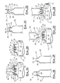
- the assembly according to the invention comprises a first container 10, represented in FIG. 1, containing a first product, in particular an oxidant, and a second container 20, represented in particular in FIGS. 2C to 2F, containing a second product, in particular a dye. oxidation.
- the two mixed products are intended to form a hair composition.
- the first container shown in Figure 1, is a tube 10 made of polyethylene. It comprises a body 11 on which is mounted a head 12.
- the head 12 consists of a shoulder 19 which connects the body 11 to a threaded neck 13 on its outer wall.
- An axial chimney 15, coaxial with the neck 13 is mounted to inside of it.
- An annular disk 18 in which vent openings 18a are provided connects the chimney and the neck. The annular disk delimits with the neck and the axial chimney a sealing trough which makes it possible to seal the tube 10 closed by a plug which will be described later.
- the chimney 15 defines the opening 14 of the tube 10 which allows the passage of product.
- the internal wall of the chimney 15 has a threading 16 which makes it possible, as will be explained later, to fix the second tube 20 on the first tube 10.
- a pin 30, flat at its end 31 which projects beyond the opening 14 of the tube, is fixed mounted inside the chimney 15. It is supported by a bar 33, each end is fixed on the inner wall of the chimney 15. The bar 33 thus crosses the passage formed by the chimney over its entire diameter.
- a triangular knife 32 is formed in the base of the pin supported by the bar 33, opposite the flat end 31.
- the assembly of the head 12, can be formed in one piece, by injection.
- the tube 10 is closed by a removable plug 40, shown in particular in Figure 2A.
- Part of the inner wall of the plug 40 is provided with a complementary thread of the thread 17 of the neck 15 so that the plug can be fixed on the first tube 10.
- the plug 40 thus makes it possible to close the opening 14 of the first tube and also to protect the flat pin 30.
- An annular wall 42 is advantageously provided inside the plug to be housed in the sealing channel formed between the neck and the chimney when the plug 40 is screwed onto the tube 10.
- the removable cap is advantageously provided with a breakable end 41 which can be broken in response to a twisting movement about the axis of the first tube. When the end is removed, an orifice is released which allows the passage of the composition after mixing the two products.
- the stopper has a shape suitable for use as an applicator tip to easily apply to the hair the mixed composition.
- the second container shown in particular in FIGS. 2C to 2F, is also in the form of a tube 20. It is an aluminum tube formed by a body whose end ends with a neck 21, and whose other end, not shown, is closed by winding.
- the neck 21 defines an opening 22 which is closed by a cover 23.
- the cover 23 is a thin aluminum film obtained directly during the manufacture of the aluminum tube.
- the neck 21 has a thread 24 on its outer wall, the thread 24 can be screwed inside the chimney 15 of the first tube 10, thanks to the complementary thread 16 provided on its inner wall.
- the second tube 20 is closed by a cylindrical plug 25 formed by a wall 27 and by a first skirt provided with a thread 26 complementary to the thread 24 of the neck of the second tube.
- a needle 28 is provided on the wall 27, opposite the threaded skirt, to perforate the aluminum film 23. In order to protect the needle, it is surrounded by a second skirt which extends for example the first skirt constituting the plug.
- FIGS. 2A to 2H The assembly which has just been described is used as follows, shown in FIGS. 2A to 2H.
- the user firstly has a tube 10 containing an oxidant cream, the tube 10 being closed by its plug 40 as shown in FIG. 2A. It removes the plug 40 to release the opening 14 of the tube 10, as shown in Figure 2B.
- the user disposes of the tube 20 containing a coloring cream, and which is closed by its stopper 25 (FIG. 2C).
- the user unscrews the cap 25, the lid 23 now still closed tube (Figure 2D).
- the cap is then turned and engaged around the neck 21 of the tube.
- the needle 28 engages inside the neck 21 and pierces the lid 23 as shown in Figure 2E.
- the opening 22 of the tube 20 is then released ( Figure 2F).
- the user can then threadingly engage the neck 21 of the tube 20 within the axial shaft 15 of the tube 10, as illustrated in Figures 2G and 2H.
- the user empties the tube 20 by pressing its walls and transfers all of the coloring cream into the tube 10 containing the oxidizing cream.
- the user revises the cap 40 on the tube 10, then agitates the tube 10 thus closed to homogenize the mixture. Finally, it breaks the end 41 of the stopper and applies the coloring composition in a conventional manner.
- the assembly according to the invention is used in the manner illustrated in Figures 3A to 3D.
- the user has the tube 10 containing an oxidizer cream, the tube 10 being closed by its cap 40 that unscrews to release the opening 14 of the tube 10 ( Figures 3A and 3B).
- the tube 20 closed by its cover 23 is then engaged in the tube 10, as illustrated in Figure 3C.
- the lid 23 then abuts against the end 31 of the flat pin 30 which projects beyond the opening 14 of the tube 10 without the neck 21 of the tube 20 being able to engage in the chimney 15 of the container 10.
- the user feeling a resistance, is brought to stop its engagement movement and to remove the lid with the needle 28 provided on the plug 25 of the tube 20. It can then screw the neck 21 of the tube 20 in the chimney 15 of the tube 10 as illustrated in Figures 2G and 2H.
- the user if the user continues to engage the two tubes without removing the lid, it must push the neck 21 of the tube 20 in the chimney 15 of the tube 10 with a force such that the flat pin 30 tears the operculum 23 The screwing of the neck 21 into the chimney 15 is then possible.
- the triangular knife 32 cuts the operculum perforated so as to clear the opening 22 of the tube 20 ( Figure 3D). As described above, the user empties the coloring cream in the tube 10, performs the mixing and applies the coloring composition obtained on the hair.
Landscapes
- Engineering & Computer Science (AREA)
- Mechanical Engineering (AREA)
- Closures For Containers (AREA)
- Package Specialized In Special Use (AREA)
- Coating Apparatus (AREA)
- Accessories For Mixers (AREA)
- Pharmaceuticals Containing Other Organic And Inorganic Compounds (AREA)
- Fats And Perfumes (AREA)
- Medicines Containing Plant Substances (AREA)
- Cosmetics (AREA)
Claims (20)
- Einheit zur bedarfsmäßigen Mischung von zwei Produkten zur Herstellung einer insbesondere kosmetischen Zusammensetzung, die aufweist: a) einen ersten Behälter (10), der ein erstes Produkt enthält und eine erste Öffnung (14) begrenzt, wobei der erste Behälter mit ersten Kopplungsmitteln (16) versehen ist; b) einen zweiten Behälter (20), der ein zweites Produkt enthält und eine zweite Öffnung (22) definiert, die von einer Abdeckfolie (23) verschlossen wird, wobei der zweite Behälter mit zweiten Kopplungsmitteln (24) versehen ist, die in der Lage sind, mit den ersten Kopplungsmitteln (16) in Eingriff zu kommen, dadurch gekennzeichnet, dass der erste Behälter (10) ein Sicherheitsorgan (30) aufweist, das so angeordnet ist, dass es vor dem Ineingriff bringen der ersten und zweiten Kopplungsmittel (16; 24) mit der Abdeckfolie (23) in Eingriff kommt.
- Einheit nach Anspruch 1, dadurch gekennzeichnet, dass das Sicherheitsorgan (30) aus einem Zäckchen besteht, von dem mindestens ein Teil aus der ersten Öffnung (14) nach außerhalb des ersten Behälters vorsteht.
- Einheit nach Anspruch 2, dadurch gekennzeichnet, dass das Zäckchen (30) ein Ende (31) aufweist, das eine ebene Oberfläche hat, die mit der Abdeckfolie (23) in Eingriff kommen kann.
- Einheit nach einem der vorhergehenden Ansprüche, dadurch gekennzeichnet, dass der erste Behälter (10) ein Öffnungselement (32) aufweist, das beim Ineingriffbringen der ersten und zweiten Kopplungsmittel (16, 24) in der Lage ist, das völlige oder teilweise Freilegen der zweiten Öffnung zu bewirken, um die Verbindung des ersten und zweiten Behälters und die Mischung des ersten und des zweiten Produkts zu ermöglichen.
- Einheit nach Anspruch 4, dadurch gekennzeichnet, dass das Öffnungselement (32) eine Schneidevorrichtung, insbesondere in Form eines Trokar, aufweist, die in der Lage ist, beim Ineingriffbringen der ersten und zweiten Kopplungsmittel (16; 24) das vollständige oder teilweise Abschneiden der Abdeckfolie (23) zu bewirken.
- Einheit nach Anspruch 5, dadurch gekennzeichnet, dass die Schneidevorrichtung (32) in der Verlängerung des Sicherheitsorgans (30) entgegengesetzt zu dem Ende (31) ausgebildet ist, das mit der Abdeckfolie (23) in Eingriff kommen kann.
- Einheit nach einem der vorhergehenden Ansprüche, dadurch gekennzeichnet, dass die ersten Kopplungsmittel aus einem ersten Gewinde (16) bestehen, während die zweiten Kopplungsmittel aus einem zweiten Gewinde (24) komplementär zum ersten bestehen.
- Einheit nach einem der vorhergehenden Ansprüche, dadurch gekennzeichnet, dass die erste Öffnung (14) des ersten Behälters (10) von einem axialen Schacht (15) begrenzt wird, der die ersten Kopplungsmittel (16) und das Sicherheitsorgan (30) trägt, wobei der axiale Schacht (15) innerhalb eines Halses (13) ausgebildet ist, der vom ersten Behälter gebildet wird.
- Einheit nach Anspruch 8, dadurch gekennzeichnet, dass der axiale Schacht (15) mit dem Hals (13) über ein insbesondere ringförmiges Verbindungselement (18) verbunden ist, wobei das Verbindungselement mindestens eine Lüftungsöffnung (18a) aufweist, um bei der Herstellung der Mischung das Entweichen von Luft zu ermöglichen.
- Einheit nach einem der Ansprüche 8 oder 9, dadurch gekennzeichnet, dass der axiale Schacht (15) und der Hals (13) einen Kopf (12) bilden, der einstückig insbesondere durch Spritzen erhalten wird.
- Einheit nach Anspruch 10, dadurch gekennzeichnet, dass der erste Behälter (10) von einem Körper (11) gebildet wird, auf dem der Kopf (12) durch Schweißen oder Kleben befestigt ist.
- Einheit nach einem der vorhergehenden Ansprüche, dadurch gekennzeichnet, dass ein entfernbarer Verschlussdeckel (40) vorgesehen ist, um die erste Öffnung (14) des ersten Behälters (10) zu verschließen und das Sicherheitsorgan (30) zu schützen.
- Einheit nach Anspruch 12, dadurch gekennzeichnet, dass der entfernbare Verschlussdeckel (40) mit einem abtrennbaren Ende (41) versehen ist, um nach der Herstellung der Mischung als Auftragtülle zu dienen.
- Einheit nach Anspruch 12 oder 13, dadurch gekennzeichnet, dass der Hals (15) ein Gewinde (17) aufweist, das vorgesehen ist, um die Befestigung des entfernbaren Verschlussdeckels (40) am ersten Behälter (10) zu gewährleisten.
- Einheit nach einem der vorhergehenden Ansprüche, dadurch gekennzeichnet, dass der zweite Behälter (20) mit einem entfernbaren Verschlussdeckel (25) versehen ist, der in der Lage ist, in einer ersten Stellung mittels des zweiten Kopplungsmittels (24) so am zweiten Behälter befestigt zu werden, dass er die Abdeckfolie (23) schützt, und in einer zweiten Stellung die Abdeckfolie (23) zu durchbohren.
- Einheit nach Anspruch 15, dadurch gekennzeichnet, dass der Verschlussdeckel (25) eine Wand (27) aufweist, die auf einer Seite eine Schürze, die mit einem zum Gewinde (24) des zweiten Behälters komplementären Gewinde (26) versehen ist, und auf der anderen Seite ein Durchbohrungsorgan (28) trägt.
- Einheit nach einem der vorhergehenden Ansprüche, dadurch gekennzeichnet, dass der erste Behälter (10) aus einer Tube, insbesondere aus Polyethylen, mit elastisch verformbaren Wänden besteht.
- Einheit nach einem der vorhergehenden Ansprüche, dadurch gekennzeichnet, dass der zweite Behälter (20) aus einer Tube besteht.
- Einheit nach Anspruch 18, dadurch gekennzeichnet, dass die Tube (20) aus Aluminium ist, während die Abdeckfolie (23) ein Aluminiumfilm ist.
- Verwendung einer Einheit nach einem der vorhergehenden Ansprüche zur Herstellung einer kosmetischen Zusammensetzung, insbesondere zur Haarpflege, wobei das erste Produkt ein Oxidationsmittel und das zweite Produkt ein Farbmittel ist.
Applications Claiming Priority (2)
| Application Number | Priority Date | Filing Date | Title |
|---|---|---|---|
| FR0100086A FR2818964B1 (fr) | 2001-01-04 | 2001-01-04 | Ensemble pour le melange extemporane de deux produits |
| FR0100086 | 2001-01-04 |
Publications (2)
| Publication Number | Publication Date |
|---|---|
| EP1221419A1 EP1221419A1 (de) | 2002-07-10 |
| EP1221419B1 true EP1221419B1 (de) | 2006-08-16 |
Family
ID=8858521
Family Applications (1)
| Application Number | Title | Priority Date | Filing Date |
|---|---|---|---|
| EP01403170A Expired - Lifetime EP1221419B1 (de) | 2001-01-04 | 2001-12-07 | Vorrichtung zum unmittelbaren Vermischen von zwei Produkten |
Country Status (8)
| Country | Link |
|---|---|
| US (1) | US7156227B2 (de) |
| EP (1) | EP1221419B1 (de) |
| JP (1) | JP2002255768A (de) |
| AT (1) | ATE336443T1 (de) |
| CA (1) | CA2365381A1 (de) |
| DE (1) | DE60122277T2 (de) |
| ES (1) | ES2269331T3 (de) |
| FR (1) | FR2818964B1 (de) |
Families Citing this family (12)
| Publication number | Priority date | Publication date | Assignee | Title |
|---|---|---|---|---|
| DE102004028921A1 (de) * | 2004-06-15 | 2006-01-05 | Sempre Hair-Color-Mix Gmbh | Flaschensatz |
| US7377383B2 (en) * | 2005-06-27 | 2008-05-27 | Henry John R | Multi-chamber container for mixing ingredients at time of use |
| US20080289976A1 (en) * | 2005-06-27 | 2008-11-27 | Henry John R | Container attachable to another container for mixing ingredients |
| ES2389040T3 (es) * | 2008-02-05 | 2012-10-22 | L'oréal | Cabezal de tubo y procedimiento de realización |
| US20090308889A1 (en) * | 2008-06-11 | 2009-12-17 | Frank Lindsay | Container system |
| AU2009329274A1 (en) * | 2008-12-19 | 2011-08-11 | Iptree Trust (Truns Number 503/2009) | A liquid key for use with pumpable explosives |
| WO2014028745A2 (en) | 2012-08-17 | 2014-02-20 | Archon Pharmaceutical Consulting Llc | A system for compounding and packaging ready to reconstitute drug powders of solutions to a solution or to a suspension or to an injectable |
| FR3023688B1 (fr) | 2014-07-17 | 2017-12-29 | Rodolphe Pouzet | Dispositif pour la preparation d'un produit cosmetique a partir d'une cartouche, cartouche adaptee |
| FR3046995A1 (fr) * | 2016-01-21 | 2017-07-28 | Universkin | Kit de preparation d'une composition extemporanee |
| GB2559594B (en) * | 2017-02-10 | 2020-07-15 | Dexos Drinks Ltd | A liquid dispenser and method |
| US10279977B2 (en) | 2017-08-25 | 2019-05-07 | Eli Fleischman | Fluid container for having stackable sections connected by valves for transmitting fluid between the sections |
| WO2019113276A1 (en) * | 2017-12-08 | 2019-06-13 | Unipharma, Llc | Container and method for reconstitution of substances |
Family Cites Families (9)
| Publication number | Priority date | Publication date | Assignee | Title |
|---|---|---|---|---|
| US3941270A (en) * | 1974-01-25 | 1976-03-02 | Allied Chemical Corporation | Removable seal for liquid containers |
| GB2200888B (en) * | 1987-02-12 | 1991-05-29 | Ici Plc | A closed container into which additive can be introduced |
| GB2208227A (en) * | 1988-08-11 | 1989-03-15 | Ici Plc | Introducing additive into a container |
| FR2680357B1 (fr) * | 1991-08-16 | 1995-01-06 | Oreal | Conditionnement a deux flacons permettant de stocker separement l'un de l'autre deux produits, notamment liquides, et de les melanger au moment de leur utilisation. |
| FR2685301B1 (fr) * | 1991-12-20 | 1995-03-10 | Oreal | Ensemble destine au melange de deux produits differents stockes separement. |
| FR2763048B1 (fr) * | 1997-05-06 | 1999-07-09 | Oreal | Conditionnement pour le melange extemporane de deux produits |
| JPH10316176A (ja) * | 1997-05-19 | 1998-12-02 | Kamaya Kagaku Kogyo Co Ltd | 二液混合容器 |
| FR2767797B1 (fr) * | 1997-09-01 | 1999-10-08 | Oreal | Dispositif pour le melange extemporane d'au moins deux produits |
| FR2810639B1 (fr) * | 2000-06-21 | 2002-09-06 | Oreal | Ensemble pour le melange extemporane de deux produits |
-
2001
- 2001-01-04 FR FR0100086A patent/FR2818964B1/fr not_active Expired - Fee Related
- 2001-12-07 ES ES01403170T patent/ES2269331T3/es not_active Expired - Lifetime
- 2001-12-07 AT AT01403170T patent/ATE336443T1/de not_active IP Right Cessation
- 2001-12-07 EP EP01403170A patent/EP1221419B1/de not_active Expired - Lifetime
- 2001-12-07 DE DE60122277T patent/DE60122277T2/de not_active Expired - Fee Related
-
2002
- 2002-01-03 CA CA002365381A patent/CA2365381A1/fr not_active Abandoned
- 2002-01-04 US US10/035,204 patent/US7156227B2/en not_active Expired - Fee Related
- 2002-01-04 JP JP2002000199A patent/JP2002255768A/ja not_active Withdrawn
Also Published As
| Publication number | Publication date |
|---|---|
| DE60122277T2 (de) | 2007-08-09 |
| US20020104766A1 (en) | 2002-08-08 |
| DE60122277D1 (de) | 2006-09-28 |
| US7156227B2 (en) | 2007-01-02 |
| FR2818964B1 (fr) | 2003-02-21 |
| EP1221419A1 (de) | 2002-07-10 |
| CA2365381A1 (fr) | 2002-07-04 |
| ATE336443T1 (de) | 2006-09-15 |
| JP2002255768A (ja) | 2002-09-11 |
| FR2818964A1 (fr) | 2002-07-05 |
| ES2269331T3 (es) | 2007-04-01 |
Similar Documents
| Publication | Publication Date | Title |
|---|---|---|
| EP1167231B1 (de) | Einheit zum unmittelbaren Vermischen von zwei Produkten | |
| EP1136386B1 (de) | Vorrichtung zum unmittelbaren Vermischen von mindestens zwei Produkten | |
| CA2057889C (fr) | Verseur pour des flacons et recipients analogues, avec un element perceur pour percer un opercule du goulot des recipients | |
| EP0572645B1 (de) | Vorrichtung zur mischung von zwei verschiedenen und getrennt aufbewahrten produkten | |
| FR2813869A1 (fr) | Dispositif pour le conditionnement separe et la sortie conjointe de deux produits a melanger de facon extemporanee | |
| EP0238371B1 (de) | Behälter mit einer viskosen Flüssigkeit, die beim ersten Verbrauch mit einem Zusatz versehen werden kann | |
| EP1300344A1 (de) | Vorrichtung zur getrennten Aufbewahrung und zum Zusammenspenden von zwei Produkten | |
| EP1033323B1 (de) | Behälter zur Mischung von verschiedenen Komponenten zur Bildung eines Produktes | |
| EP0293290A1 (de) | Verschlussvorrichtung für Behälter | |
| CA2278668A1 (fr) | Recipient distributeur multichambre pour le stockage d'au moins deux substances, le melange extemporane de celles-ci et la distribution du melange | |
| EP1221419A1 (de) | Vorrichtung zum unmittelbaren Vermischen von zwei Produkten | |
| EP1751023B1 (de) | Verteilvorrichtung für parfum | |
| EP0905049B1 (de) | Behälter für ein Dreikomponenten-Produkt | |
| EP1475315B1 (de) | Vorrichtung zum Aufbewahren und Aufbringen von flüssigen Produkten | |
| EP2146908B1 (de) | Behälterkappe mit zusätzlicher aufnahmekapazität | |
| EP0562943B1 (de) | Zweikammerpackung | |
| CA2344199A1 (fr) | Recipient a ouverture propre et bouchon correspondant | |
| EP1557371B1 (de) | Kit mit zwei Behältern und einem Applikator | |
| FR2475003A1 (fr) | Dispositif de conditionnement separe de deux produits destines a etre melanges au moment de l'emploi | |
| FR2796369A1 (fr) | Recipient a ouverture propre et bouchon correspondant | |
| FR2615828A1 (fr) | Dispositif de fermeture pour recipients | |
| FR2667049A1 (fr) | Flacon double corps. | |
| WO2014170175A1 (fr) | Dispositif de conditionnement pour produit cosmétique dégazant |
Legal Events
| Date | Code | Title | Description |
|---|---|---|---|
| PUAI | Public reference made under article 153(3) epc to a published international application that has entered the european phase |
Free format text: ORIGINAL CODE: 0009012 |
|
| AK | Designated contracting states |
Kind code of ref document: A1 Designated state(s): AT BE CH CY DE DK ES FI FR GB GR IE IT LI LU MC NL PT SE TR |
|
| AX | Request for extension of the european patent |
Free format text: AL;LT;LV;MK;RO;SI |
|
| 17P | Request for examination filed |
Effective date: 20030110 |
|
| AKX | Designation fees paid |
Designated state(s): AT BE CH CY DE DK ES FI FR GB GR IE IT LI LU MC NL PT SE TR |
|
| GRAP | Despatch of communication of intention to grant a patent |
Free format text: ORIGINAL CODE: EPIDOSNIGR1 |
|
| GRAS | Grant fee paid |
Free format text: ORIGINAL CODE: EPIDOSNIGR3 |
|
| GRAA | (expected) grant |
Free format text: ORIGINAL CODE: 0009210 |
|
| AK | Designated contracting states |
Kind code of ref document: B1 Designated state(s): AT BE CH CY DE DK ES FI FR GB GR IE IT LI LU MC NL PT SE TR |
|
| PG25 | Lapsed in a contracting state [announced via postgrant information from national office to epo] |
Ref country code: AT Free format text: LAPSE BECAUSE OF FAILURE TO SUBMIT A TRANSLATION OF THE DESCRIPTION OR TO PAY THE FEE WITHIN THE PRESCRIBED TIME-LIMIT Effective date: 20060816 Ref country code: FI Free format text: LAPSE BECAUSE OF FAILURE TO SUBMIT A TRANSLATION OF THE DESCRIPTION OR TO PAY THE FEE WITHIN THE PRESCRIBED TIME-LIMIT Effective date: 20060816 Ref country code: NL Free format text: LAPSE BECAUSE OF FAILURE TO SUBMIT A TRANSLATION OF THE DESCRIPTION OR TO PAY THE FEE WITHIN THE PRESCRIBED TIME-LIMIT Effective date: 20060816 Ref country code: IE Free format text: LAPSE BECAUSE OF FAILURE TO SUBMIT A TRANSLATION OF THE DESCRIPTION OR TO PAY THE FEE WITHIN THE PRESCRIBED TIME-LIMIT Effective date: 20060816 |
|
| REG | Reference to a national code |
Ref country code: GB Ref legal event code: FG4D Free format text: NOT ENGLISH |
|
| REG | Reference to a national code |
Ref country code: CH Ref legal event code: EP |
|
| REG | Reference to a national code |
Ref country code: IE Ref legal event code: FG4D Free format text: LANGUAGE OF EP DOCUMENT: FRENCH |
|
| REF | Corresponds to: |
Ref document number: 60122277 Country of ref document: DE Date of ref document: 20060928 Kind code of ref document: P |
|
| PG25 | Lapsed in a contracting state [announced via postgrant information from national office to epo] |
Ref country code: SE Free format text: LAPSE BECAUSE OF FAILURE TO SUBMIT A TRANSLATION OF THE DESCRIPTION OR TO PAY THE FEE WITHIN THE PRESCRIBED TIME-LIMIT Effective date: 20061116 Ref country code: DK Free format text: LAPSE BECAUSE OF FAILURE TO SUBMIT A TRANSLATION OF THE DESCRIPTION OR TO PAY THE FEE WITHIN THE PRESCRIBED TIME-LIMIT Effective date: 20061116 |
|
| GBT | Gb: translation of ep patent filed (gb section 77(6)(a)/1977) |
Effective date: 20061101 |
|
| PG25 | Lapsed in a contracting state [announced via postgrant information from national office to epo] |
Ref country code: CH Free format text: LAPSE BECAUSE OF NON-PAYMENT OF DUE FEES Effective date: 20061231 Ref country code: LI Free format text: LAPSE BECAUSE OF NON-PAYMENT OF DUE FEES Effective date: 20061231 Ref country code: MC Free format text: LAPSE BECAUSE OF NON-PAYMENT OF DUE FEES Effective date: 20061231 Ref country code: BE Free format text: LAPSE BECAUSE OF NON-PAYMENT OF DUE FEES Effective date: 20061231 |
|
| PG25 | Lapsed in a contracting state [announced via postgrant information from national office to epo] |
Ref country code: PT Free format text: LAPSE BECAUSE OF FAILURE TO SUBMIT A TRANSLATION OF THE DESCRIPTION OR TO PAY THE FEE WITHIN THE PRESCRIBED TIME-LIMIT Effective date: 20070116 |
|
| NLV1 | Nl: lapsed or annulled due to failure to fulfill the requirements of art. 29p and 29m of the patents act | ||
| REG | Reference to a national code |
Ref country code: IE Ref legal event code: FD4D |
|
| REG | Reference to a national code |
Ref country code: ES Ref legal event code: FG2A Ref document number: 2269331 Country of ref document: ES Kind code of ref document: T3 |
|
| PLBE | No opposition filed within time limit |
Free format text: ORIGINAL CODE: 0009261 |
|
| STAA | Information on the status of an ep patent application or granted ep patent |
Free format text: STATUS: NO OPPOSITION FILED WITHIN TIME LIMIT |
|
| 26N | No opposition filed |
Effective date: 20070518 |
|
| REG | Reference to a national code |
Ref country code: CH Ref legal event code: PL |
|
| BERE | Be: lapsed |
Owner name: L'OREAL Effective date: 20061231 |
|
| PG25 | Lapsed in a contracting state [announced via postgrant information from national office to epo] |
Ref country code: GR Free format text: LAPSE BECAUSE OF FAILURE TO SUBMIT A TRANSLATION OF THE DESCRIPTION OR TO PAY THE FEE WITHIN THE PRESCRIBED TIME-LIMIT Effective date: 20061117 |
|
| PG25 | Lapsed in a contracting state [announced via postgrant information from national office to epo] |
Ref country code: TR Free format text: LAPSE BECAUSE OF FAILURE TO SUBMIT A TRANSLATION OF THE DESCRIPTION OR TO PAY THE FEE WITHIN THE PRESCRIBED TIME-LIMIT Effective date: 20060816 Ref country code: LU Free format text: LAPSE BECAUSE OF NON-PAYMENT OF DUE FEES Effective date: 20061207 |
|
| PG25 | Lapsed in a contracting state [announced via postgrant information from national office to epo] |
Ref country code: CY Free format text: LAPSE BECAUSE OF FAILURE TO SUBMIT A TRANSLATION OF THE DESCRIPTION OR TO PAY THE FEE WITHIN THE PRESCRIBED TIME-LIMIT Effective date: 20060816 |
|
| PGFP | Annual fee paid to national office [announced via postgrant information from national office to epo] |
Ref country code: IT Payment date: 20081220 Year of fee payment: 8 |
|
| PGFP | Annual fee paid to national office [announced via postgrant information from national office to epo] |
Ref country code: ES Payment date: 20090120 Year of fee payment: 8 Ref country code: FR Payment date: 20081212 Year of fee payment: 8 |
|
| PGFP | Annual fee paid to national office [announced via postgrant information from national office to epo] |
Ref country code: DE Payment date: 20081205 Year of fee payment: 8 |
|
| PGFP | Annual fee paid to national office [announced via postgrant information from national office to epo] |
Ref country code: GB Payment date: 20081203 Year of fee payment: 8 |
|
| GBPC | Gb: european patent ceased through non-payment of renewal fee |
Effective date: 20091207 |
|
| REG | Reference to a national code |
Ref country code: FR Ref legal event code: ST Effective date: 20100831 |
|
| PG25 | Lapsed in a contracting state [announced via postgrant information from national office to epo] |
Ref country code: FR Free format text: LAPSE BECAUSE OF NON-PAYMENT OF DUE FEES Effective date: 20091231 |
|
| PG25 | Lapsed in a contracting state [announced via postgrant information from national office to epo] |
Ref country code: DE Free format text: LAPSE BECAUSE OF NON-PAYMENT OF DUE FEES Effective date: 20100701 |
|
| PG25 | Lapsed in a contracting state [announced via postgrant information from national office to epo] |
Ref country code: GB Free format text: LAPSE BECAUSE OF NON-PAYMENT OF DUE FEES Effective date: 20091207 |
|
| PG25 | Lapsed in a contracting state [announced via postgrant information from national office to epo] |
Ref country code: IT Free format text: LAPSE BECAUSE OF NON-PAYMENT OF DUE FEES Effective date: 20091207 |
|
| REG | Reference to a national code |
Ref country code: ES Ref legal event code: FD2A Effective date: 20110404 |
|
| PG25 | Lapsed in a contracting state [announced via postgrant information from national office to epo] |
Ref country code: ES Free format text: LAPSE BECAUSE OF NON-PAYMENT OF DUE FEES Effective date: 20110322 |
|
| PG25 | Lapsed in a contracting state [announced via postgrant information from national office to epo] |
Ref country code: ES Free format text: LAPSE BECAUSE OF NON-PAYMENT OF DUE FEES Effective date: 20091208 |