EP1221532A1 - Panneau pour porte sectionnelle - Google Patents
Panneau pour porte sectionnelle Download PDFInfo
- Publication number
- EP1221532A1 EP1221532A1 EP00204834A EP00204834A EP1221532A1 EP 1221532 A1 EP1221532 A1 EP 1221532A1 EP 00204834 A EP00204834 A EP 00204834A EP 00204834 A EP00204834 A EP 00204834A EP 1221532 A1 EP1221532 A1 EP 1221532A1
- Authority
- EP
- European Patent Office
- Prior art keywords
- panel
- panels
- door
- wall
- front wall
- Prior art date
- Legal status (The legal status is an assumption and is not a legal conclusion. Google has not performed a legal analysis and makes no representation as to the accuracy of the status listed.)
- Withdrawn
Links
- 230000006378 damage Effects 0.000 description 4
- 208000027418 Wounds and injury Diseases 0.000 description 3
- 208000014674 injury Diseases 0.000 description 3
- 239000000463 material Substances 0.000 description 3
- 229910052751 metal Inorganic materials 0.000 description 2
- 239000002184 metal Substances 0.000 description 2
- 239000004033 plastic Substances 0.000 description 2
- 229920005830 Polyurethane Foam Polymers 0.000 description 1
- 239000004411 aluminium Substances 0.000 description 1
- 229910052782 aluminium Inorganic materials 0.000 description 1
- XAGFODPZIPBFFR-UHFFFAOYSA-N aluminium Chemical compound [Al] XAGFODPZIPBFFR-UHFFFAOYSA-N 0.000 description 1
- 238000005452 bending Methods 0.000 description 1
- 238000010276 construction Methods 0.000 description 1
- 230000007797 corrosion Effects 0.000 description 1
- 238000005260 corrosion Methods 0.000 description 1
- 230000006866 deterioration Effects 0.000 description 1
- 230000008030 elimination Effects 0.000 description 1
- 238000003379 elimination reaction Methods 0.000 description 1
- 230000013011 mating Effects 0.000 description 1
- 229920003023 plastic Polymers 0.000 description 1
- 239000011496 polyurethane foam Substances 0.000 description 1
- 230000000284 resting effect Effects 0.000 description 1
Images


Classifications
-
- E—FIXED CONSTRUCTIONS
- E06—DOORS, WINDOWS, SHUTTERS, OR ROLLER BLINDS IN GENERAL; LADDERS
- E06B—FIXED OR MOVABLE CLOSURES FOR OPENINGS IN BUILDINGS, VEHICLES, FENCES OR LIKE ENCLOSURES IN GENERAL, e.g. DOORS, WINDOWS, BLINDS, GATES
- E06B3/00—Window sashes, door leaves, or like elements for closing wall or like openings; Layout of fixed or moving closures, e.g. windows in wall or like openings; Features of rigidly-mounted outer frames relating to the mounting of wing frames
- E06B3/32—Arrangements of wings characterised by the manner of movement; Arrangements of movable wings in openings; Features of wings or frames relating solely to the manner of movement of the wing
- E06B3/48—Wings connected at their edges, e.g. foldable wings
- E06B3/485—Sectional doors
Definitions
- the invention relates to panels used for the construction of sectional doors of industrial or civil structures such as warehouses, garages and the like.
- the panels are connected to each other in a hinged manner so as to form a folding structure which is guided by guides provided in the adjacent wall, during its movements upwards or downwards in order to open and close the door.
- the abovementioned panels have a substantially parallelepiped shape and usually are made externally of sheet metal; they are rendered thermally insulating by injecting polyurethane foam or the like inside them, but there also exist panels which are internally empty or in any case made in a different manner and using other materials (plastic, wood, aluminium, etc.).
- each of them is profiled with a convex surface while the bottom edge with a matching concave surface, so that when the panels are vertically aligned to form the door, these surfaces rest facing each other; said surfaces also have a centre of curvature which coincides substantially with the axis of rotation of the adjacent hinged panels.
- the joining hinges of the panels are generally arranged on the inner side thereof, namely on their faces directed towards the inside of the garage, warehouse or other premises closed by the door.
- contact between the surfaces of the panels may cause deterioration thereof over time; reference could be made, for example, to the case of painted or galvanized surfaces: it can be understood that the bearing contact between one panel and another may damage their surface lining, thereby exposing the panels to the risk of corrosion by the external environment.
- the present invention aims at remedying this state of the art.
- its object is to provide a panel for sectional doors in which the axis of rotation is positioned between the planes where its inner and outer faces lie, without giving rise to the risk of injury to a person's fingers when the door is operated and without requiring mutual bearing contact between the panels in order to align them vertically, when the door is in the closed position.
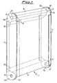
- numeral 1 denotes overall a panel according to the invention for sectional doors of industrial warehouses, garages and other similar premises.
- the panel 1 has two facing flat walls 2 and 3 which are oriented respectively towards the inside and towards the outside of the area closed by the door and which form the visible surfaces thereof; for this reason, the walls 2 and 3 of the panel will also be called hereafter the inner face and outer face.
- the walls 2, 3 are preferably made of sheet metal, as is generally the case with this type of panel, but could also be made of other suitable material (such as plastics, etc.); similarly, the inside of the panel may be filled with any material or may be empty and also reinforced with honeycomb structures and the like.
- the panel 1 has a top edge 4 and a bottom edge 5 at the ends of the walls 2 and 3, which are shaped in the manner that will be better explained below; the panel is also closed along its transverse sides by two sections 6 and 7 terminating at the top and at the bottom in respective end parts 6a, 6b and 7a, 7b, wherein holes 8 and 9 are provided.
- the convex surface 10 is connected to a flat surface 12 parallel to the faces 2 and 3 of the panel; in accordance with a preferred embodiment of the invention, this flat surface 12 lies on the centre line between the two faces 2 and 3 as well as the centre of rotation of the hinge 15 which connects two adjacent panels in the door shown in Figures 2 and 3.
- the centre of rotation of the hinge also coincides with that of the curvature of the convex surface 10; for this purpose, the pivot 16 of the hinge is housed inside a recess 17 formed along the flat surface 12 so that its centre is coplanar with the latter and therefore also lies on the centre line of the panel 1.
- the profile of the top edge 4 of the panel 1 terminates in a bevelled surface 18, which is inclined at about 45° with respect to the flat surface 12 and joins the wall 2.
- This bevelled surface is identical and symmetrical, with respect to a plane transverse to the vertically aligned panels (like in Fig. 2) passing through the axis of rotation of the hinge 15,to a second bevelled surface 19 present on the profile of the bottom edge 5.
- the latter also has a concave surface 20 matching the convex surface of the bottom edge and is connected to the external wall 3 of the panel at a tip 21; preferably the distance between the latter and the rounded step 11 of the top edge of an adjacent panel is such as to prevent a person's fingers from remaining trapped when the panels rotate with respect to each other during closing of the door.
- the hinge 15 comprises two arms 28, 29 like to each other and each configured along a broken line which, from the pivot 16, follows the profile of the panels connected by the said hinge.
- a first portion 28a, 29a of these arms extends along the flat surface 12 of the top edge 4 of a panel when the latter is vertically aligned with the adjacent panel as shown in Fig. 2, while a second portion 28b, 29b extends respectively along the bevelled surfaces 18 and 19; the terminal portion 28c, 29c of the hinge arms is then fixed to the inner wall 2 of the panels by means of screws in a manner known per se.
- the hinged connection of the panels is also ensured by bolts passing through holes 8 and 9 provided in the respective sections 6 and 7.
- the end parts 6a, 7a of the sections are shaped so as to be arranged alongside those 6b, 7b of the other panel, thereby bringing the respective holes 8, 9 into alignment so that the aforementioned bolts (not shown in the drawings) may be inserted therein.
- these holes are also coaxial with the pivots 16 of the hinges 15 which connect the panels and are arranged along the recess 17 of their top edge 4.
- the convex surface 10 and concave surface 20 of each of them allow their relative movement, preventing the introduction of fingers there between, in accordance with the principles of the known art.
- the axis of relative rotation of the panels is located in an advanced position with respect to the inner wall 2 thereof, thereby achieving the advantages arising therefrom and mentioned above; however, it can be easily understood that owing to the presence of the bevelled surfaces 18 and 19, all the stepped zones which were present in the panels of the prior art have been eliminated.
- the angle of inclination of the bevelled surfaces 18 and 19 will be chosen depending on the maximum rotation envisaged for the two panels, so as to maintain the safety distance between them in any condition; preferably, the aforementioned inclination should in any case be such that the bevelled surfaces rest parallel (as in Fig. 3) when the maximum rotation of the panels is reached.
- the hinge 15 provides for halting the relative rotation of the panels, since it acts as an abutment stop owing to a part thereof which comes into abutment against the edge 4 of the same panel where the abovementioned axis of rotation is situated.
- the panel for sectional doors according to the invention achieves the object set out initially of having an axis of rotation arranged between the planes of its inner and outer faces, overcoming at the same time the drawbacks relating to the known panels in the art.
- the aforementioned bolts could be sufficient for the hinged connection of the panels; however, in such a case the panels would be supported only at their ends so that they could bend and touch one another along their respective concave and convex surfaces, if they were long and/or heavy.
- the panel 1 is connected to the adjacent panels in the door, both by means of the hinges 15 and by means of the bolts passing through the holes 8 and 9 in the sections 6, 7; in this manner the hinges are able to avoid longitudinal bending of the connected panels, thereby preventing any possible contact between them.
- the present invention can be advantageously applied to panels such as those in the example referred to above, where the transverse sides are formed by sections used for the engagement of bolts or the like, in the hinged connection of the panels.
- Another advantage achieved by the invention consists in the possibility of arranging the axis of rotation of the panels, coplanar with the flat surface 12 lying along the centre plane between the inner and outer walls 2 and 3.
- the door is centered with respect to the roller guides present in the side wall which defines the opening closed by it; the aforementioned rollers are arranged along the axis of rotation of the panels, in a position away therefrom.
- both the convex surface 10 and the concave surface 20 extend from the outer face 3 of the panel to its centre line; this configuration allows the presence of bevelled surfaces 18, 19, which are symmetrical with respect to a median plane transverse to the walls of each panel, such that when they are vertically aligned they are also symmetrical with respect to the horizontal plane which passes through the axis of rotation of the hinges (cf. Figure 2).
- Figure 4 shows, using the same numbering referred to before, a cross-sectional view of the top edge 4 of the panel.
- this variant differs from the preceding one in that the convex surface 10 has, formed along it, a groove 30 which runs along the top edge 4 and is used to house a seal between the convex surface and the matching concave surface 20 of an adjacent panel in the door.
Landscapes
- Engineering & Computer Science (AREA)
- Civil Engineering (AREA)
- Structural Engineering (AREA)
- Securing Of Glass Panes Or The Like (AREA)
Priority Applications (1)
| Application Number | Priority Date | Filing Date | Title |
|---|---|---|---|
| EP00204834A EP1221532A1 (fr) | 2000-12-28 | 2000-12-28 | Panneau pour porte sectionnelle |
Applications Claiming Priority (1)
| Application Number | Priority Date | Filing Date | Title |
|---|---|---|---|
| EP00204834A EP1221532A1 (fr) | 2000-12-28 | 2000-12-28 | Panneau pour porte sectionnelle |
Publications (1)
| Publication Number | Publication Date |
|---|---|
| EP1221532A1 true EP1221532A1 (fr) | 2002-07-10 |
Family
ID=8172587
Family Applications (1)
| Application Number | Title | Priority Date | Filing Date |
|---|---|---|---|
| EP00204834A Withdrawn EP1221532A1 (fr) | 2000-12-28 | 2000-12-28 | Panneau pour porte sectionnelle |
Country Status (1)
| Country | Link |
|---|---|
| EP (1) | EP1221532A1 (fr) |
Citations (3)
| Publication number | Priority date | Publication date | Assignee | Title |
|---|---|---|---|---|
| US2300265A (en) * | 1940-05-13 | 1942-10-27 | Crawford Door Co | Hinge for door construction |
| EP0370376A2 (fr) * | 1988-11-25 | 1990-05-30 | Hörmann KG Brockhagen | Vantail de porte |
| DE19815826C1 (de) * | 1998-04-09 | 1999-09-30 | Debo International B V | Sektionaltorblatt für Garagen- und Industrietore |
-
2000
- 2000-12-28 EP EP00204834A patent/EP1221532A1/fr not_active Withdrawn
Patent Citations (4)
| Publication number | Priority date | Publication date | Assignee | Title |
|---|---|---|---|---|
| US2300265A (en) * | 1940-05-13 | 1942-10-27 | Crawford Door Co | Hinge for door construction |
| EP0370376A2 (fr) * | 1988-11-25 | 1990-05-30 | Hörmann KG Brockhagen | Vantail de porte |
| DE3938021A1 (de) * | 1988-11-25 | 1990-05-31 | Hoermann Kg | Torblatt |
| DE19815826C1 (de) * | 1998-04-09 | 1999-09-30 | Debo International B V | Sektionaltorblatt für Garagen- und Industrietore |
Similar Documents
| Publication | Publication Date | Title |
|---|---|---|
| US5718276A (en) | Thermoplastic interlocking panels | |
| AU2002227283B2 (en) | Overhead garage door | |
| US4924932A (en) | Thermoplastic shutter having horizontal sections | |
| US6328091B1 (en) | Upward acting sectional door with pinch resistant edge profile between door panels | |
| US5168915A (en) | Garage door | |
| US9279282B2 (en) | Frame for a window and a method for making a frame | |
| US4315345A (en) | Profiled hinge joint | |
| EP0428589A4 (en) | Connection system | |
| CA2351945C (fr) | Panneaux de portes pliantes suspendues avec leurs raccords articules | |
| US6129132A (en) | Sectional closing doors | |
| KR101779561B1 (ko) | 폴딩도어 | |
| GB2072248A (en) | Roller shutters | |
| EP0031970A1 (fr) | Articulation de charnière profilée | |
| US6648052B2 (en) | Sectional door with panel aligning abutment | |
| EP0037448A1 (fr) | Eléments de fermeture | |
| EP1571282B1 (fr) | Porte ou fenêtre notamment pour bâtiments ou embarcations | |
| EP1221532A1 (fr) | Panneau pour porte sectionnelle | |
| US6568149B2 (en) | Sealed garage door joint with thermal break | |
| EP1375805B1 (fr) | Porte d'accès pour porte sectionnelle avec éléments interchangeables | |
| US20240418030A1 (en) | Configurable astragal and snap feature for fenestration systems | |
| WO1995016844A1 (fr) | Systeme de montage de porte | |
| CA2504987C (fr) | Porte de batiment composee de plusieurs panneaux articules entre eux | |
| EP1316667B1 (fr) | Elément modulaire pour portes sectionnelles | |
| US20040168777A1 (en) | Pinchless multi-panel door | |
| EP1895083B1 (fr) | Porte coulissante avec un système d'ouverture pivotant d'urgence |
Legal Events
| Date | Code | Title | Description |
|---|---|---|---|
| PUAI | Public reference made under article 153(3) epc to a published international application that has entered the european phase |
Free format text: ORIGINAL CODE: 0009012 |
|
| AK | Designated contracting states |
Kind code of ref document: A1 Designated state(s): AT BE CH CY DE DK ES FI FR GB GR IE IT LI LU MC NL PT SE TR |
|
| AX | Request for extension of the european patent |
Free format text: AL;LT;LV;MK;RO;SI |
|
| AKX | Designation fees paid | ||
| REG | Reference to a national code |
Ref country code: DE Ref legal event code: 8566 |
|
| STAA | Information on the status of an ep patent application or granted ep patent |
Free format text: STATUS: THE APPLICATION IS DEEMED TO BE WITHDRAWN |
|
| 18D | Application deemed to be withdrawn |
Effective date: 20030111 |