EP1222088B2 - Siege de vehicule comprenant une position rabattue - Google Patents
Siege de vehicule comprenant une position rabattue Download PDFInfo
- Publication number
- EP1222088B2 EP1222088B2 EP01980312A EP01980312A EP1222088B2 EP 1222088 B2 EP1222088 B2 EP 1222088B2 EP 01980312 A EP01980312 A EP 01980312A EP 01980312 A EP01980312 A EP 01980312A EP 1222088 B2 EP1222088 B2 EP 1222088B2
- Authority
- EP
- European Patent Office
- Prior art keywords
- seat
- backrest
- seat cushion
- vehicle seat
- feet
- Prior art date
- Legal status (The legal status is an assumption and is not a legal conclusion. Google has not performed a legal analysis and makes no representation as to the accuracy of the status listed.)
- Expired - Lifetime
Links
Images


Classifications
-
- B—PERFORMING OPERATIONS; TRANSPORTING
- B60—VEHICLES IN GENERAL
- B60N—SEATS SPECIALLY ADAPTED FOR VEHICLES; VEHICLE PASSENGER ACCOMMODATION NOT OTHERWISE PROVIDED FOR
- B60N2/00—Seats specially adapted for vehicles; Arrangement or mounting of seats in vehicles
- B60N2/02—Seats specially adapted for vehicles; Arrangement or mounting of seats in vehicles the seat or part thereof being movable, e.g. adjustable
- B60N2/0292—Multiple configuration seats, e.g. for spacious vehicles or mini-buses
-
- B—PERFORMING OPERATIONS; TRANSPORTING
- B60—VEHICLES IN GENERAL
- B60N—SEATS SPECIALLY ADAPTED FOR VEHICLES; VEHICLE PASSENGER ACCOMMODATION NOT OTHERWISE PROVIDED FOR
- B60N2/00—Seats specially adapted for vehicles; Arrangement or mounting of seats in vehicles
- B60N2/005—Arrangement or mounting of seats in vehicles, e.g. dismountable auxiliary seats
- B60N2/015—Attaching seats directly to vehicle chassis
- B60N2/01508—Attaching seats directly to vehicle chassis using quick release attachments
- B60N2/01516—Attaching seats directly to vehicle chassis using quick release attachments with locking mechanisms
- B60N2/01583—Attaching seats directly to vehicle chassis using quick release attachments with locking mechanisms locking on transversal elements on the vehicle floor or rail, e.g. transversal rods
-
- B—PERFORMING OPERATIONS; TRANSPORTING
- B60—VEHICLES IN GENERAL
- B60N—SEATS SPECIALLY ADAPTED FOR VEHICLES; VEHICLE PASSENGER ACCOMMODATION NOT OTHERWISE PROVIDED FOR
- B60N2/00—Seats specially adapted for vehicles; Arrangement or mounting of seats in vehicles
- B60N2/24—Seats specially adapted for vehicles; Arrangement or mounting of seats in vehicles for particular purposes or particular vehicles
- B60N2/30—Non-dismountable or dismountable seats storable in a non-use position, e.g. foldable spare seats
- B60N2/3002—Non-dismountable or dismountable seats storable in a non-use position, e.g. foldable spare seats back-rest movements
- B60N2/3029—Non-dismountable or dismountable seats storable in a non-use position, e.g. foldable spare seats back-rest movements by composed movement
- B60N2/3031—Non-dismountable or dismountable seats storable in a non-use position, e.g. foldable spare seats back-rest movements by composed movement in a longitudinal-vertical plane
-
- B—PERFORMING OPERATIONS; TRANSPORTING
- B60—VEHICLES IN GENERAL
- B60N—SEATS SPECIALLY ADAPTED FOR VEHICLES; VEHICLE PASSENGER ACCOMMODATION NOT OTHERWISE PROVIDED FOR
- B60N2/00—Seats specially adapted for vehicles; Arrangement or mounting of seats in vehicles
- B60N2/24—Seats specially adapted for vehicles; Arrangement or mounting of seats in vehicles for particular purposes or particular vehicles
- B60N2/30—Non-dismountable or dismountable seats storable in a non-use position, e.g. foldable spare seats
- B60N2/3038—Cushion movements
- B60N2/304—Cushion movements by rotation only
- B60N2/3045—Cushion movements by rotation only about transversal axis
- B60N2/305—Cushion movements by rotation only about transversal axis the cushion being hinged on the vehicle frame
-
- B—PERFORMING OPERATIONS; TRANSPORTING
- B60—VEHICLES IN GENERAL
- B60N—SEATS SPECIALLY ADAPTED FOR VEHICLES; VEHICLE PASSENGER ACCOMMODATION NOT OTHERWISE PROVIDED FOR
- B60N2/00—Seats specially adapted for vehicles; Arrangement or mounting of seats in vehicles
- B60N2/24—Seats specially adapted for vehicles; Arrangement or mounting of seats in vehicles for particular purposes or particular vehicles
- B60N2/30—Non-dismountable or dismountable seats storable in a non-use position, e.g. foldable spare seats
- B60N2/3088—Non-dismountable or dismountable seats storable in a non-use position, e.g. foldable spare seats characterised by the mechanical link
- B60N2/309—Non-dismountable or dismountable seats storable in a non-use position, e.g. foldable spare seats characterised by the mechanical link rods
Definitions
- the invention relates to a vehicle seat, in particular a motor vehicle seat, with the features of the preamble of claim 1.
- the second and / or third rows of multi-purpose vehicles are usually designed so that the interior is adjustable to a passenger or goods transport.
- MPV multi-purpose vehicles
- a vehicle seat with a so-called package is known to reach the backrest is folded onto the seat cushion and then folded after loosening the rear foot of the entire vehicle seat by about 90 ° to the front, so that a large cargo area is created.
- the problem may occur that before reaching the packing position, the headrest comes into contact with the vehicle floor and prevents further folding.
- the operation leaves many wishes unfulfilled.
- the US 4,736,985 A shows a arranged at a level of the vehicle structure vehicle seat of the type mentioned, the seat cushion folds in the transition to the package position about an arranged in the middle to rear seat cushion area axis down while the seat cushion hinged backrest at the same time performs an offset movement forward.
- the invention is based on the object to improve a vehicle seat of the type mentioned. This object is achieved by a vehicle seat with the features of claim 1.
- Advantageous embodiments are the subject of the dependent claims.
- the back For the transition from the sitting position to the package position, after loosening the corresponding feet, the back performs an offset movement in the direction of the seat cushion, which is at least approximately without tilting the backrest, a striking of the backrest or its headrest is avoided on the vehicle floor, as a rule also a striking on the vehicle sky.
- the feet In the usual orientation of the vehicle seat, the feet are loosened at the back and the backrest is offset forwards, with a remaining at rest remaining front foot hinged first coupling serves as a pivoting arm for the rear foot.
- the solution according to the invention is suitable both for passenger seats and for the second row of seats and possibly existing additional rows of seats.
- the seat cushion folds up with a pivotal movement, i. in the usual orientation of the vehicle seat to the front high, without that it must carry the backrest.
- the pivot axis is provided in the front region of the seat cushion carrier.
- the fold-up makes room for the offset of the backrest forward and at the same time saves space, since two vehicle seats can be arranged in the package order one behind the other.
- the movements of the backrest and the seat cushion between the sitting position and the package position are coupled by coupling means.
- This allows one-handed operation all the way, so easy transition into the package ("Easy Package"), since then automatically the seat cushion and the backrest can be transferred together in the different positions.
- Such a design with simplified operation is ideal for three-row seating arrangements, since the occupant of the third row of seats can then easily get off after he himself has moved the inventively designed second row of seats in the package.
- a second coupling is provided, which causes the pivoting of the seat cushion upon actuation of the backrest.
- About the second coupling can be placed in a flat non-use position during a Vorschwenken the backrest and the seat cushion, in particular in articulation of the seat cushion carrier by means of a four-bar linkage.
- the said coupling can for example be done by a slot-pin guide, which defines a path with a single degree of freedom and at the same time can serve to compensate for tolerances.
- the slot-pin guide can be provided in principle between any two components of all moving components.
- the definition of the web can also be done by the interaction of several coupling.
- a gas spring which supports the pivoting movement of the seat cushion, can keep the effort required for the transition to the package order low.
- the vehicle seat can be connected to the vehicle structure in various seat longitudinal positions and optionally completely removed by all feet are solvable and different mounting options are provided on the vehicle structure or against each other sliding seat rails of known design for connecting the feet.
- a fuse determines the vehicle seat, preferably automatically, ie without further action by the operator. The occupants are then better protected against the cargo in crash situations, and the vehicle seat does not unintentionally leave the package.
- the feet present in the area of the backrest have fastening means which serve both for securing the feet to the vehicle structure and for securing the package position.
- fasteners with two functions reduce the manufacturing costs.
- a pawl may be provided which can hook in two differently arranged bolts, or vice versa, a bolt with two pawls cooperate.
- the rear feet are locked with the front feet, so that the vehicle seat occupies a compact shape and can be easily removed.
- the automatic package backup is eliminated.
- a single control element is provided for triggering the transition to the package position and for triggering the return to the sitting position, which simplifies the operation of the vehicle seat. This control then unlocks the bifunctional fastener.
- the operating element is arranged easily accessible, for example, in the region of the upper edge of the backrest.
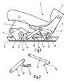
- a vehicle seat 1 for the rear of a motor vehicle for example a van
- the backrest 5 is arranged in the forward direction of travel behind the seat cushion 3.
- the seat cushion 3 is provided with a seat cushion support 9, on each of which a front foot 11 is hinged on the outside in its front end region on both sides of the substantially symmetrical vehicle seat 1, wherein the pivot axes defined thereby are aligned with each other.
- the left side of the vehicle seat will be described, initially in the seat position of the vehicle seat 1 suitable for passenger transportation.
- the front foot 11 is arranged with its lower part in an aligned in the vehicle and seat longitudinal direction, vehicle-fixed rail 13, pushed back over a seat transverse direction, rail-mounted, middle rail bolt 15, from above via a seat transverse direction aligned, rail-mounted, front rail bolts 17 pushed and releasably locked by means of a hinged on the front foot 11, front pawl 19 which hooks spring loaded on the front rail pin 17.
- the front rail bolt 17 is arranged in the longitudinal direction behind the pivot point between the front foot 11 and seat cushion carrier 9.
- a rear foot 21 is aligned with its lower part from above via a seat transverse direction, rail-fixed, rear rail pin 23 pushed and releasably locked by means of a rear foot 21, rear pawl 25 which hooks spring loaded on the rear rail pin 23.
- the backrest 5 is attached, for example by means of hinge fittings for tilt adjustment.
- a first coupling 29 is articulated as a link on the one hand on the rear foot 21 on the inside and on the other hand on the front foot 11 on the outside thereof.
- a second coupling 31 is articulated on the one hand on the seat cushion carrier 9 on the inside and on the other hand on the rear foot 21 on the inside.
- the seat cushion support 9, the front and rear feet 11 and 21 and the coupling 29 and 31 form a hinged seat frame of the vehicle seat. 1
- the second coupling 31 is provided at its hinged end at the rear end 21 with an arm 33 which points in the sitting position forward and slightly down.
- the arm 33 carries a sliding block 35, preferably a pin aligned in the seat transverse direction.
- the first coupling 29 is provided in the region of its hinged at the rear end 21 end with a seat post in the rear facing link arm 37, which has a laterally open, slot-shaped gate 39.
- the sliding block 35 of the second coupling 31 engages in the link 39 of the first coupling 29 in the manner of a slot-pin guide.
- a gas spring 41 is articulated on the one hand on the front foot 11 and on the other hand on the seat cushion carrier 9, in each case in the rear regions thereof.
- the rear pawl 25 is unlocked by means of a control element 43 attached to the backrest 5, preferably in the region of its upper edge.
- the gas spring 41 now pushes the seat cushion carrier 9 with the seat cushion 3 so up that this performs a pivotal movement forward with the articulation point on the front foot 11 as a rotation axis.
- the rear foot 21 is pulled over the second coupling 31 to the front, wherein the first coupling 29 serves as a pivoting arm.
- the sliding block 35 of the second coupling 31 moves within the gate 39 of the first coupling 29, whereby the forward movement of the rear foot 21 is defined.
- the backrest 5 is moved forward.
- a securing bolt 45 is provided above the receptacle for the front rail bolt 17 and slightly offset to the rear, which projects laterally outwardly from the front foot 11 in the seat transverse direction.
- the package is reached when the rear foot 21 is seated on the safety pin 45 and the rear pawl 25 automatically hooks on the safety pin 45.
- the package is thereby automatically secured, which increases the protection against cargo.
- the vehicle seat 1 can also be removed from the motor vehicle.
- the two front pawls 19 are unlocked by means of a running between two front feet 11 Entriegelungsbügels 47, so that the double pin locking the two front feet 11 is released.
- the automatic securing of the package order is independent of this.
- the automatic package security i. the rear pawl 25 detaches from the securing bolt 45.
- the backrest 5 is moved backwards. Due to the coupling 29 and 31 and their link guide and this movement can be performed with one hand.
- the rear pawl 25 falls back to the rear rail bolt 23 for securing.
- the bolts for connecting the vehicle seat 1 to the vehicle floor are provided in a rail 13 fixed to the vehicle structure.
- several, suitably spaced bolts in the longitudinal direction of the rail 13 may be present.
- the bolts are provided for connection to an upper rail of a pair of seat rails, which is guided slidingly in a vehicle-structural fixed lower rail. This allows a variety of seat longitudinal positions set.
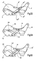
- first coupling 29 'acting between the front foot 11' and the rear foot 21 is formed in an elongate shape, while the second coupling 31 'provided between the seat cushion support 9 and the rear foot 21 carries a curved link 39'.
- this curved backdrop 39 ' engages a sliding block 35' of the front foot 11 'a.
- Both the first and the second coupling 29 'and 31 are formed in an elongated shape.
- a sliding block 35 ' is provided, which is guided by a link 39" of the rear foot 21 ".
- a third modification according to Fig. 5C agrees the front foot 11 with the first embodiment and the two couplers 29 'and 31''' correspond to the second modification, and on the rear foot 21 '' is mounted a sliding block 35 '' which engages in a slot 39 '''of the seat cushion carrier 9'' Fig. 5D
- the feet 11 and 21 coincide with the first embodiment, and the seat cushion support 9 "'together with the link 39"' and the second link 31 "with the third modification
- the sliding block 35""guided by the link 39"" is at the upper end of the first Belt 29 "" attached.
- the second embodiment in turn largely coincides with the first embodiment, in particular with regard to the mode of operation and the connection to the vehicle structure, unless it is described differently below.
- the same and equivalent components therefore carry by 100 higher reference numerals.
- the seat cushion support 109 is articulated on the front foot 111.
- the backrest 121 carrying the backrest is articulated to the front foot 111 by means of the first coupling 129.
- the second coupling 131 between the seat cushion carrier 109 and the rear foot 121 pulls the rear foot 121 forward at the transition to the package position.
- the movement of the rear foot 121 is defined in contrast to the first embodiment and its modifications not by a slot-pin guide, but by a third coupling 149 which is hinged to the front foot 111 and the second coupling 131.
- the production of the individual components is simplified thereby.
- the modified components bear reference numerals with apostrophes.
- the third coupling 149 ' is provided between the front foot 111' and the rear foot 121 ', so that the third coupling 149' together with the first coupling 129 and the two feet 111 'and 121' forms a four-bar linkage.
- the third coupling 149 "acts between the first coupling 129 and the second coupling 131.
- a third modification according to FIG Fig. 6D is formed on the first coupling 129 "', an arm on which the third coupling 149"' is articulated with one end. At its other end, the third coupling 149 "" is articulated on the seat cushion carrier 109.
- the third embodiment again largely agrees with the first embodiment, in particular with regard to the mode of operation during the transition to the package position and the connection to the vehicle structure, unless it is described differently below.
- the same and equivalent components therefore carry 200 higher reference numerals.
- the vehicle seat 201 with its seat cushion 203 on the seat cushion support 209 and its backrest 205 is also provided on each side with a front foot 211 and a rear foot 221.
- a first coupling 229 which is articulated on the two feet 211 and 221, has at the upper end a link 239 in which a sliding block 235 of a T-shaped second coupling 231 is guided.
- the second coupling 231 acts between the seat cushion 203 and the backrest 205.
- a load bearing coupling 251 and, secondly offset to the top a control coupling 253 articulated, i. the seat cushion support 209 is articulated by means of a four-bar linkage.
- the components act essentially as in the first embodiment together.
- the vehicle seat 201 can be lowered to a floor position (flat-floor position). If the backrest 205 is pivoted forwardly into a flat position, it pushes the seat cushion 203 downward via the second coupling 231.
- the seat cushion support 209 can be lowered by the four-bar linkage to the front foot 211.
- the movement of the rear foot 221 ' is not defined by a slot-pin guide.
- a third coupling 249 is provided in the region of the rear foot 221 ', which, as in the first modification of the second embodiment, is articulated between the front foot 211 and the rear foot 221'. Together with the first coupling 229 it also forms a four-bar linkage.
- the L-shaped, second coupling 231 'between the seat cushion and the backrest is simpler than the third embodiment.
Landscapes
- Engineering & Computer Science (AREA)
- Aviation & Aerospace Engineering (AREA)
- Transportation (AREA)
- Mechanical Engineering (AREA)
- Seats For Vehicles (AREA)
Claims (10)
- Siège de véhicule, en particulier siège de véhicule automobile qui peut être réglé entre au moins une position d'assise appropriée pour le transport de personnes et une position de charge repliée, comprenanta) une carcasse de siège articulée (9, 11, 21, 29, 31) possédant des pieds avant (11; 11'; 111; 111'; 211) et des pieds arrière (2 1; 21"; 21"'; 121; 121'; 221) qui sont destinés à être fixés à la structure du véhicule de façon détachable,b) un coussin d'assise (3; 203) qui est muni d'un support de coussin d'assise (9; 99"'; 109; 209) qui est articulé aux pieds avant (11; 11'; 111; 111'; 211), le coussin d'assise (3; 203) étant redressé par un mouvement de pivotement lors du passage de la position d'assise à la position de charge tandis que les pieds avant (11; 11'; 111; 111'; 211) restent non déplacés,c) un dossier (5; 205) qui, lors du passage de la position d'assise à la position de charge, après le déblocage des pieds arrière (21; 21"; 21"'; 121; 121'; 221) présents dans sa région, décrit un mouvement de décalage, le dossier (5; 205) étant disposé derrière le coussin d'assise (3; 203) redressé dans la position de charge, etd) des moyens d'accouplement (29, 31; 29', 31'; 31"; 29""; 129, 129"', 131, 149;149'; 149"; 149"'; 149""; 229, 231; 229', 231', 249, 251, 253) possédant des première et deuxième biellettes (29, 31; 29', 31'; 31"; 29""; 129, 131; 129"'; 229, 231; 229', 231') avec lesquelles les mouvements du dossier (5; 205) et du coussin d'assise (3; 203) entre la position d'assise et la position de charge sont accouplés,
caractérisé en ce quee) la première biellette (29; 29'; 29""; 129, 229; 229') est articulée, d'une part au pied arrière (21;21"; 21"'; 121; 121'; 221) et, d'autre part, au pied avant (11; 11'; 111; 111'; 211), cependant que, lors du mouvement de déplacement du dossier (5; 205) en direction du coussin d'assise (3; 203), la première biellette (29; 29'; 29""; 129, 229; 229') sert de bras pivotant du pied arrière (21; 21"; 21"'; 121; 121'),f) la deuxième biellette (31; 31'; 31"; 131; 231; 231') est articulée, d'une part, au support de coussin d'assise (9; 9"'; 109) et, d'autre part, à un pied arrière (21; 21"; 21"'; 121; 121'), ou agit entre le coussin d'assise (203) et le dossier (205), etg) le support de coussin d'assise (9; 9"'; 109; 209) est articulé aux pieds avant (11; 11'; 111; 111'; 211) dans sa région d'extrémité avant. - Siège de véhicule selon la revendication 1, caractérisé en ce que, pendant le mouvement de déplacement du dossier (5; 205), le coussin d'assise (3; 203) se redresse avec ledit mouvement de pivotement autour de la zone d'articulation dans la région d'extrémité avant du support de coussin d'assise (9; 9"'; 109; 209) en tant qu'axe de rotation, les surfaces du coussin d'assise (3; 203) et du dossier (5; 205) qui sont dirigés vers l'utilisateur dans la position d'assise, pointent au moins approximativement dans la même direction dans la position de charge.
- Siège de véhicule selon la revendication 1 ou 2, caractérisé en ce que la deuxième biellette (31; 31'; 31"; 131; 231; 231') tire le pied arrière (21; 21"; 21"'; 121; 121') vers l'avant lors du mouvement de déplacement du dossier (5; 205).
- Siège de véhicule selon une des revendications 1 à 3, caractérisé en ce que le dossier (205) peut être rabattu vers l'avant dans une position à plat, dans laquelle il repousse le coussin d'assise (203) vers le bas par l'intermédiaire de la deuxième biellette (231; 231') agitent entre le coussin d'assise (203) et le dossier (205),
- Siège de véhicule selon une des revendications 1 à 4, caractérisé en ce que les moyens d'accouplement (29, 31; 29', 31'; 32' ; 29""; 129, 129"', 131, 149; 149'; 149"; 149"'; 149""; 229, 231; 229', 231', 249) présentent un guidage à fente et tourillon (35; 39; 35', 39'; 39"; 35"', 39"'; 35""; 235, 239).
- Siège de véhicule selon une des revendications 1 à 5, caractérisé en ce que les pieds avant (11; 11'; 111; 111'; 211) et les pieds arrière (21; 21"; 21'"; 121; 121'; 221) peuvent être reliés à la structure du véhicule dans différentes positions longitudinales du siège de véhicule (1; 201) et en ce que le siège de véhicule (1; 201) peut être sélectivement retiré entièrement après le déblocage de tous les pieds (11, 21; 11'; 21"; 21'"; 111, 121; 111', 121'; 211, 221).
- Siège de véhicule selon une des revendications 1 à 6, caractérisé en ce qu'il est prévu un ressort à gaz (41) qui assiste le mouvement de pivotement du coussin d'assise (3; 203).
- Siège de véhicule selon une des revendications 1 à 7, caractérisé en ce que les pieds arrière (21; 21"; 21"'; 121; 121'; 221) présentent des moyens de fixation (25) qui servent aussi bien pour la fixation des pieds arrière (21; 21"; 21"'; 121; 121'; 221) à la structure du véhicule que pour le blocage (25, 45) de la position de charge du siège de véhicule (1; 201) par immobilisation de ce dernier.
- Siège de véhicule selon une des revendications 1 à 8, caractérisé en ce que, dans la position de charge, les pieds arrière (21; 21"; 21"'; 121; 121'; 221) peuvent être verrouillés avec les pieds avant (11; 11'; 111; 111'; 211).
- Siège de véhicule selon une des revendications 1 à 9, caractérisé en ce qu'un unique élément de manoeuvre (43) est prévu pour déclencher le passage à la position de charge et pour déclencher le retour à la position d'assise.
Priority Applications (3)
| Application Number | Priority Date | Filing Date | Title |
|---|---|---|---|
| DE20122354U DE20122354U1 (de) | 2000-09-14 | 2001-08-31 | Fahrzeugsitz mit Packagestellung |
| DE20122324U DE20122324U1 (de) | 2000-09-14 | 2001-08-31 | Fahrzeugsitz mit Packagestellung |
| DE20122325U DE20122325U1 (de) | 2000-09-14 | 2001-08-31 | Fahrzeugsitz mit Packagestellung |
Applications Claiming Priority (3)
| Application Number | Priority Date | Filing Date | Title |
|---|---|---|---|
| DE10045474A DE10045474C5 (de) | 2000-09-14 | 2000-09-14 | Fahrzeugsitz mit Packagestellung |
| DE10045474 | 2000-09-14 | ||
| PCT/EP2001/010058 WO2002022391A1 (fr) | 2000-09-14 | 2001-08-31 | Siege de vehicule comprenant une position rabattue |
Publications (3)
| Publication Number | Publication Date |
|---|---|
| EP1222088A1 EP1222088A1 (fr) | 2002-07-17 |
| EP1222088B1 EP1222088B1 (fr) | 2003-10-29 |
| EP1222088B2 true EP1222088B2 (fr) | 2009-09-16 |
Family
ID=7656187
Family Applications (1)
| Application Number | Title | Priority Date | Filing Date |
|---|---|---|---|
| EP01980312A Expired - Lifetime EP1222088B2 (fr) | 2000-09-14 | 2001-08-31 | Siege de vehicule comprenant une position rabattue |
Country Status (6)
| Country | Link |
|---|---|
| US (1) | US6655738B2 (fr) |
| EP (1) | EP1222088B2 (fr) |
| JP (1) | JP3722798B2 (fr) |
| BR (1) | BR0107209B1 (fr) |
| DE (2) | DE10045474C5 (fr) |
| WO (1) | WO2002022391A1 (fr) |
Cited By (1)
| Publication number | Priority date | Publication date | Assignee | Title |
|---|---|---|---|---|
| FR3152448A1 (fr) * | 2023-08-29 | 2025-03-07 | Faurecia Sièges d'Automobile | Siège de véhicule et procédé d’utilisation du siège |
Families Citing this family (91)
| Publication number | Priority date | Publication date | Assignee | Title |
|---|---|---|---|---|
| DE10139538C1 (de) * | 2001-08-10 | 2003-03-20 | Faurecia Autositze Gmbh & Co | Fondsitz für Kraftfahrzeuge |
| US6676216B1 (en) * | 2002-03-22 | 2004-01-13 | Lear Corporation | Vehicle seat assembly |
| FR2845325B1 (fr) * | 2002-10-08 | 2006-01-13 | Faurecia Sieges Automobile | Siege de vehicule automobile |
| US6860562B2 (en) * | 2002-11-05 | 2005-03-01 | Fisher Dynamics Corporation | Fold, tumble, and kneel seat assembly |
| US6857703B2 (en) * | 2002-11-05 | 2005-02-22 | Fisher Dynamics Corporation | Fold, tumble and kneel seat assembly |
| FR2847211B1 (fr) * | 2002-11-19 | 2005-02-04 | Faurecia Sieges Automobile | Siege de vehicule automobile |
| US7140680B2 (en) | 2003-01-22 | 2006-11-28 | L&P Property Management Company | Fold down seat lumbar support apparatus and method |
| US7137664B2 (en) | 2003-01-22 | 2006-11-21 | L&P Property Management Company | Automatically actuating ergonomic support system for a fold down seat |
| US6736459B1 (en) * | 2003-04-17 | 2004-05-18 | Lear Corporation | Spring element seat |
| DE10328176B3 (de) | 2003-06-18 | 2005-03-17 | Keiper Gmbh & Co. Kg | Fahrzeugsitz, insbesondere Kraftfahrzeugsitz |
| US7073862B2 (en) * | 2003-07-31 | 2006-07-11 | Intier Automotive Inc. | Tumble seat assembly having locking strut |
| KR100521198B1 (ko) * | 2003-10-21 | 2005-10-17 | 기아자동차주식회사 | 차량의 싱킹시트 |
| US6899392B1 (en) * | 2003-10-31 | 2005-05-31 | Lear Corporation | Stadium slide seat |
| EP2289732B1 (fr) * | 2003-10-31 | 2016-04-13 | Johnson Controls Technology Company | Procédé pour escamotage de sièges de deuxième et troisième rangée dans une position de chargement sur le plancher |
| DE102004047250B4 (de) * | 2003-11-07 | 2014-10-30 | Volkswagen Ag | Verstellbarer Sitz für Fahrzeuge |
| US7775595B2 (en) | 2004-02-06 | 2010-08-17 | Schukra Of North America | Drive mechanism |
| DE102004007863A1 (de) * | 2004-02-17 | 2005-09-08 | Johnson Controls Gmbh | Fahrzeugsitz, insbesondere für ein Kraftfahrzeug, mit einer klappbaren Lehne und einer klappbaren Sitzbasis und Verfahren |
| KR100569945B1 (ko) * | 2004-04-27 | 2006-04-10 | 기아자동차주식회사 | 차량용 시트의 더블폴딩 고정을 위한 록킹기구 |
| EP1771315B1 (fr) | 2004-07-30 | 2008-12-10 | L&P Property Management Company | Support lombaire modulaire |
| DE102004039249B4 (de) * | 2004-08-13 | 2006-08-10 | Keiper Gmbh & Co.Kg | Fahrzeugsitz mit Bodenstellung |
| US7152921B2 (en) | 2004-08-18 | 2006-12-26 | Lear Corporation | Vehicle seat |
| DE102004057471B4 (de) * | 2004-11-21 | 2010-09-23 | Bayerische Motoren Werke Aktiengesellschaft | Fahrzeugsitz, insbesondere Kraftfahrzeugsitz |
| US20060113828A1 (en) * | 2004-12-01 | 2006-06-01 | Ryan Christopher J | Flip and slide seat assembly |
| US7121624B2 (en) * | 2005-01-13 | 2006-10-17 | Fisher Dynamics Corporation | Seat assembly having manual tumble with interlock and powered recline, fold and kneel |
| WO2006089191A1 (fr) * | 2005-02-18 | 2006-08-24 | Johnson Controls Technology Company | Siege de vehicule |
| JP4561413B2 (ja) * | 2005-03-07 | 2010-10-13 | 日産自動車株式会社 | 車両用シート |
| US7387333B2 (en) * | 2005-04-18 | 2008-06-17 | Johnson Controls Technology Company | Seat latch |
| FR2885087B1 (fr) | 2005-04-27 | 2008-12-19 | Peugeot Citroen Automobiles Sa | Siege repliable en au moins une position pour vehicule automobile |
| FR2885558B1 (fr) | 2005-05-11 | 2007-07-06 | Faurecia Sieges Automobile | Siege pour vehicule automobile ayant une position limitant son encombrement longitudinal |
| FR2885560B1 (fr) | 2005-05-11 | 2007-07-20 | Faurecia Sieges Automobile | Siege pour vehicule automobile ayant une position avec un encombrement longitudinal reduit |
| FR2885559B1 (fr) | 2005-05-11 | 2008-12-12 | Faurecia Sieges Automobile | Siege pour vehicule automobile ayant une position avec un encombrement longitudinal limite |
| FR2885850B1 (fr) * | 2005-05-18 | 2007-07-20 | Faurecia Sieges Automobile | Arrangement d'un siege pour vehicule automobile pour limiter son encombrement longitudinal |
| DE102005022985B3 (de) * | 2005-05-19 | 2006-05-04 | Keiper Gmbh & Co.Kg | Fahrzeugsitz, insbesondere Kraftfahrzeugsitz |
| DE102005022984B4 (de) * | 2005-05-19 | 2012-09-20 | Keiper Gmbh & Co. Kg | Fahrzeugsitz, insbesondere Kraftfahrzeugsitz |
| DE102006007139B4 (de) * | 2006-02-14 | 2013-10-24 | Keiper Gmbh & Co. Kg | Fahrzeugsitz, insbesondere Kraftfahrzeugsitz |
| DE102006015922B4 (de) * | 2005-05-19 | 2009-07-30 | Keiper Gmbh & Co. Kg | Sitzschienenpaar für einen Fahrzeugsitz |
| CA2610712A1 (fr) * | 2005-06-02 | 2006-12-07 | Intier Automotive Inc. | Ensemble siege de vehicule presentant une position debout |
| DE102005060444B4 (de) | 2005-12-17 | 2008-01-10 | Keiper Gmbh & Co.Kg | Fahrzeugsitz mit Bodenstellung |
| US7309105B2 (en) * | 2006-01-09 | 2007-12-18 | L&P Property Management Company | Lift wire lumbar |
| FR2898087B1 (fr) * | 2006-03-06 | 2008-05-23 | Renault Sas | Mecanisme de verrouillage en position verticale d'un siege d'un vehicule automobile |
| WO2007112564A1 (fr) | 2006-03-30 | 2007-10-11 | Schukra Of North America, Ltd. | Système combiné de support lombaire-rembourrage latéral |
| JP4190553B2 (ja) * | 2006-07-31 | 2008-12-03 | トヨタ自動車株式会社 | 車両用シート装置 |
| KR100858189B1 (ko) * | 2006-12-13 | 2008-09-10 | 기아자동차주식회사 | 팁업 타입의 워크인 슬라이딩 시트 |
| US7568764B2 (en) | 2007-01-08 | 2009-08-04 | Ford Global Technologies, Llc | Reclining rear seat for vehicle having four-bar link |
| US7984949B2 (en) | 2007-04-24 | 2011-07-26 | Schukra Of North America | Lumbar and bolster support for second row seat |
| US7469952B2 (en) * | 2007-05-16 | 2008-12-30 | Gm Global Technology Operations, Inc. | Low profile seat stowage mechanization |
| DE102007031612B4 (de) | 2007-07-06 | 2009-06-04 | Keiper Gmbh & Co. Kg | Schwenklagerstelle eines Fahrzeugsitzes |
| DE102007036450B3 (de) * | 2007-07-31 | 2009-01-08 | Keiper Gmbh & Co.Kg | Fahrzeugsitz, insbesondere Kraftfahrzeugsitz |
| CA2712004C (fr) * | 2008-03-20 | 2017-07-18 | Magna Seating Inc. | Protection par crochet vis-a-vis d'un basculement vers l'avant pour seconde rangee |
| DE102008019527B4 (de) | 2008-04-18 | 2013-07-04 | Keiper Gmbh & Co. Kg | Fahrzeugsitz, insbesondere Kraftfahrzeugsitz |
| DE202009006984U1 (de) | 2008-06-24 | 2009-07-23 | Keiper Gmbh & Co. Kg | Fahrzeugsitz, insbesondere Kraftfahrzeugsitz |
| DE102008030234B4 (de) * | 2008-06-25 | 2019-01-10 | GM Global Technology Operations LLC (n. d. Ges. d. Staates Delaware) | Umklappbarer Fahrzeugsitz |
| DE102008050468B3 (de) | 2008-10-04 | 2010-04-22 | Keiper Gmbh & Co. Kg | Fahrzeugsitz, insbesondere Kraftfahrzeugsitz |
| JP5284063B2 (ja) * | 2008-11-28 | 2013-09-11 | トヨタ紡織株式会社 | チルトダウン式乗物シート |
| DE202010002237U1 (de) * | 2009-03-19 | 2010-07-08 | Keiper Gmbh & Co. Kg | Fahrzeugsitz, insbesondere Kraftfahrzeugsitz |
| DE202010004599U1 (de) | 2009-04-08 | 2010-07-29 | Keiper Gmbh & Co. Kg | Fahrzeugsitz, insbesondere Kraftfahrzeugsitz |
| DE102009019014B4 (de) * | 2009-04-21 | 2013-07-18 | Keiper Gmbh & Co. Kg | Fahrzeugsitz, insbesondere Kraftfahrzeugsitz |
| US8444223B2 (en) * | 2009-04-27 | 2013-05-21 | Toyota Motor Engineering & Manufacturing North America, Inc. | Folding seat assembly having automatic seat cushion tip-up |
| US8038196B2 (en) * | 2009-06-03 | 2011-10-18 | Keiper Gmbh & Co. Kg | Vehicle seat, especially motor vehicle seat |
| DE102009037816B3 (de) | 2009-08-12 | 2010-10-28 | Keiper Gmbh & Co. Kg | Fahrzeugsitz, insbesondere Kraftfahrzeugsitz |
| DE202009012526U1 (de) | 2009-09-16 | 2010-01-07 | Keiper Gmbh & Co. Kg | Schwenklagerstelle eines Fahrzeugsitzes |
| CN101823449B (zh) * | 2010-04-15 | 2012-05-23 | 浙江吉利汽车研究院有限公司 | 一种车辆中的折叠座椅 |
| US9321378B2 (en) * | 2010-10-19 | 2016-04-26 | Bae Systems Plc | Vehicle seat |
| EP2630004A1 (fr) | 2010-10-19 | 2013-08-28 | BAE Systems PLC | Siège de véhicule |
| WO2012052343A1 (fr) | 2010-10-19 | 2012-04-26 | Bae Systems Plc | Siège de véhicule |
| KR20150027742A (ko) * | 2012-06-01 | 2015-03-12 | 마그나 시팅 인크. | 후방 절첩 동작을 갖는 절첩 및 닐링 시트 |
| DE102013204802B4 (de) | 2012-09-28 | 2015-02-05 | Johnson Controls Components Gmbh & Co. Kg | Fahrzeugsitz, insbesondere Kraftfahrzeugsitz |
| JP5980434B2 (ja) | 2012-11-19 | 2016-08-31 | ジョンソン コントロールズ コンポーネンツ ゲーエムベーハー ウント コンパニー カーゲー | 車両シート、特に自動車シート |
| US8752879B1 (en) | 2013-02-06 | 2014-06-17 | Honda Motor Co., Ltd. | Vehicle with pivoting seat back and stopper member |
| JP2014196073A (ja) | 2013-03-29 | 2014-10-16 | 本田技研工業株式会社 | 車両 |
| DE102013103662A1 (de) * | 2013-04-11 | 2014-10-16 | Airbus Operations Gmbh | Haltevorrichtung für Passagiersitze und Passagiersitzsystem mit flexibler Sitzanordnung für Passagiertransportmittel |
| DE102014206849A1 (de) * | 2013-12-04 | 2015-06-11 | Johnson Controls Components Gmbh & Co. Kg | Fahrzeugsitz und Verfahren zum Fixieren eines Sitzelements |
| DE102014205725B4 (de) | 2013-12-11 | 2019-02-28 | Adient Luxembourg Holding S.À R.L. | Betätigungseinrichtung für einen fahrzeugsitz und fahrzeugsitz |
| KR101592680B1 (ko) * | 2014-04-09 | 2016-02-15 | 기아자동차주식회사 | 자동차용 스탠드업 시트 백폴딩 장치 |
| DE102014213860B4 (de) | 2014-05-15 | 2019-08-14 | Adient Luxembourg Holding S.À R.L. | Fahrzeugsitz, insbesondere Kraftfahrzeugsitz |
| WO2016171135A1 (fr) * | 2015-04-23 | 2016-10-27 | 株式会社タチエス | Siège pour véhicules |
| US10173556B2 (en) * | 2015-04-23 | 2019-01-08 | Tachi-S Co., Ltd. | Seat for vehicles |
| JP6522460B2 (ja) * | 2015-07-31 | 2019-05-29 | トヨタ紡織株式会社 | 乗物用シート |
| JP6554371B2 (ja) * | 2015-09-16 | 2019-07-31 | 株式会社タチエス | 車両用シート |
| US10065536B2 (en) * | 2015-09-24 | 2018-09-04 | Fca Us Llc | Reclining seat for a vehicle |
| CN105796256B (zh) * | 2016-03-01 | 2024-02-02 | 上海麦得可医疗器械销售有限公司 | 一种具人体搬运功能的电动轮椅 |
| WO2018046433A1 (fr) | 2016-09-08 | 2018-03-15 | Adient Luxembourg Holding S.à.r.l. | Siège de véhicule |
| CN108657035B (zh) * | 2017-03-28 | 2021-04-20 | 诺博汽车系统有限公司 | 座椅和车辆 |
| DE102018112926B4 (de) | 2018-05-30 | 2022-04-14 | Adient Engineering and IP GmbH | Fahrzeugsitz |
| FR3082793B1 (fr) * | 2018-06-22 | 2020-10-02 | Faurecia Sieges Dautomobile | Siege de vehicule automobile |
| FR3097815B1 (fr) * | 2019-06-25 | 2021-07-09 | Faurecia Sieges Dautomobile | Siège de véhicule à dossier inclinable |
| US10946776B2 (en) * | 2019-06-26 | 2021-03-16 | Ford Global Technologies, Llc | Adjustable seat assembly |
| FR3100012B1 (fr) * | 2019-08-22 | 2023-01-13 | Faurecia Sieges Dautomobile | Siège de véhicule à assise inclinable pour faciliter l’accès aux places arrière |
| KR102805145B1 (ko) * | 2019-12-10 | 2025-05-08 | 현대자동차주식회사 | 폴드 앤 다이브 시트의 시트쿠션 틸팅 장치 |
| KR20230036180A (ko) * | 2021-09-07 | 2023-03-14 | 현대자동차주식회사 | 자동차용 리어 시트 조절 장치 |
| FR3135671B1 (fr) * | 2022-05-23 | 2024-04-19 | Faurecia Sieges Dautomobile | Siège pour véhicule et véhicule comportant un tel siège |
Citations (3)
| Publication number | Priority date | Publication date | Assignee | Title |
|---|---|---|---|---|
| DE699589C (de) † | 1937-08-25 | 1940-12-02 | Heinz Doerpmund Dipl Ing | Fahrzeugkasten fuer geschlossene Personenkraftfahrzeuge |
| DE19607060C1 (de) † | 1996-02-24 | 1997-04-10 | Keiper Recaro Gmbh Co | Kraftfahrzeugsitz |
| ES2147090A1 (es) † | 1997-08-05 | 2000-08-16 | Antolin Grupo Ing Sa | Mecanismo de abatimiento para asiento trasero de vehiculos. |
Family Cites Families (20)
| Publication number | Priority date | Publication date | Assignee | Title |
|---|---|---|---|---|
| JPS5853611B2 (ja) * | 1979-06-06 | 1983-11-30 | 三井金属鉱業株式会社 | 貨客兼用自動車に於ける座席装置 |
| FR2474409A1 (fr) | 1980-01-28 | 1981-07-31 | Sable Freres Int | Siege de vehicule a assise et dossier mobiles |
| GB2095984B (en) * | 1981-04-06 | 1985-02-20 | Talbot Motor | Vehicle seats with movable backs |
| FR2589800B1 (fr) | 1985-11-08 | 1989-06-23 | Peugeot Cycles | Siege arriere transformable |
| DE3801294C2 (de) * | 1988-01-19 | 1995-01-19 | Daimler Benz Ag | Klappbarer Fahrzeugsitz |
| US4957321A (en) | 1988-10-12 | 1990-09-18 | Ford Motor Company | Stowable vehicle seat with seat back position controller |
| US4888854A (en) * | 1989-04-17 | 1989-12-26 | Chrysler Motors Corporation | Folding seat hinge assembly with quick disconnect |
| JPH0639231B2 (ja) | 1990-02-09 | 1994-05-25 | 株式会社大井製作所 | 車両用折畳み式シートの安全装置 |
| US5195795A (en) | 1992-04-01 | 1993-03-23 | Cannera Raymond C | Automotive vehicle seat assembly fully retractable below the vehicle's floor |
| FR2704493B1 (fr) | 1993-04-27 | 1995-06-16 | Renault | Siege escamotable a dossier basculant. |
| US5393116A (en) * | 1993-10-25 | 1995-02-28 | General Motors Corporation | Van-type vehicle multi-positional seat |
| CA2111725C (fr) | 1993-12-18 | 1998-10-13 | Wojciech Smuk | Mecanisme permettant d'incliner et de replier des sieges d'automobiles |
| DE4439975C2 (de) * | 1994-11-09 | 1998-08-06 | Daimler Benz Ag | Sitzanlage für Fahrzeuge |
| JPH08258600A (ja) * | 1995-03-21 | 1996-10-08 | Aisin Seiki Co Ltd | 車両用シート装置 |
| DE19533932C2 (de) * | 1995-09-13 | 1999-03-11 | Lear Corp | Sitz, insbesondere Fondsitz für Kraftfahrzeuge |
| JP3924814B2 (ja) * | 1995-09-26 | 2007-06-06 | マツダ株式会社 | 車両のシート装置 |
| US5577805A (en) * | 1995-10-10 | 1996-11-26 | General Motors Corporation | Van-type vehicle seat |
| US5641202A (en) * | 1996-01-16 | 1997-06-24 | Lear Seating Corporation | Release latch for utility seat |
| US6079763A (en) | 1998-05-06 | 2000-06-27 | Ford Global Technologies, Inc. | Foldable multi-position automotive vehicle seat |
| DE19964143C2 (de) * | 1999-09-11 | 2001-07-12 | Keiper Gmbh & Co | Fahrzeugsitz mit Packagestellung |
-
2000
- 2000-09-14 DE DE10045474A patent/DE10045474C5/de not_active Expired - Lifetime
-
2001
- 2001-08-31 JP JP2002526618A patent/JP3722798B2/ja not_active Expired - Lifetime
- 2001-08-31 WO PCT/EP2001/010058 patent/WO2002022391A1/fr not_active Ceased
- 2001-08-31 BR BRPI0107209-9A patent/BR0107209B1/pt not_active IP Right Cessation
- 2001-08-31 EP EP01980312A patent/EP1222088B2/fr not_active Expired - Lifetime
- 2001-08-31 DE DE50100867T patent/DE50100867D1/de not_active Expired - Lifetime
-
2002
- 2002-04-22 US US10/127,269 patent/US6655738B2/en not_active Expired - Lifetime
Patent Citations (3)
| Publication number | Priority date | Publication date | Assignee | Title |
|---|---|---|---|---|
| DE699589C (de) † | 1937-08-25 | 1940-12-02 | Heinz Doerpmund Dipl Ing | Fahrzeugkasten fuer geschlossene Personenkraftfahrzeuge |
| DE19607060C1 (de) † | 1996-02-24 | 1997-04-10 | Keiper Recaro Gmbh Co | Kraftfahrzeugsitz |
| ES2147090A1 (es) † | 1997-08-05 | 2000-08-16 | Antolin Grupo Ing Sa | Mecanismo de abatimiento para asiento trasero de vehiculos. |
Cited By (1)
| Publication number | Priority date | Publication date | Assignee | Title |
|---|---|---|---|---|
| FR3152448A1 (fr) * | 2023-08-29 | 2025-03-07 | Faurecia Sièges d'Automobile | Siège de véhicule et procédé d’utilisation du siège |
Also Published As
| Publication number | Publication date |
|---|---|
| DE10045474C5 (de) | 2005-12-22 |
| BR0107209A (pt) | 2002-07-09 |
| EP1222088A1 (fr) | 2002-07-17 |
| BR0107209B1 (pt) | 2011-09-06 |
| DE50100867D1 (de) | 2003-12-04 |
| JP3722798B2 (ja) | 2005-11-30 |
| EP1222088B1 (fr) | 2003-10-29 |
| JP2004509001A (ja) | 2004-03-25 |
| US20020125753A1 (en) | 2002-09-12 |
| DE10045474C1 (de) | 2002-03-07 |
| US6655738B2 (en) | 2003-12-02 |
| WO2002022391A1 (fr) | 2002-03-21 |
Similar Documents
| Publication | Publication Date | Title |
|---|---|---|
| EP1222088B2 (fr) | Siege de vehicule comprenant une position rabattue | |
| EP2284039B1 (fr) | Siège de véhicule, en particulier siège de véhicule automobile | |
| EP1488950B1 (fr) | Siège de véhicule, en particulier siège d'automobile | |
| DE19882413B4 (de) | Fahrzeugsitz mit verstellbarem umklappbarem Sitzmechanismus mit einfachem Einstieg | |
| DE102004039249B4 (de) | Fahrzeugsitz mit Bodenstellung | |
| DE10017059C1 (de) | Sitzanordnung für Fahrzeuge | |
| DE69400336T2 (de) | Klappzusatzsitz für Fahrzeuge | |
| DE60214200T2 (de) | Neigungs- und flachfaltverstellanordnung für leichten zugang | |
| EP1817198B1 (fr) | Siege de vehicule, notamment siege de vehicule automobile | |
| DE102005060444B4 (de) | Fahrzeugsitz mit Bodenstellung | |
| WO2001019640A2 (fr) | Siege de vehicule automobile a position basculee | |
| EP1687175A1 (fr) | Siege de vehicule, en particulier siege de vehicule moteur | |
| EP0211248A2 (fr) | Réglage d'un siège d'un véhicule automobile | |
| WO2014075819A1 (fr) | Siège de véhicule, en particulier siège de véhicule automobile | |
| EP0943482A2 (fr) | Agencement d'au moins deux sièges adjacents, en particulier une rangée de sièges d'un véhicule automobile | |
| DE29810333U1 (de) | Sitzmodul | |
| DE10139538C1 (de) | Fondsitz für Kraftfahrzeuge | |
| DE19533932A1 (de) | Sitz, insbesondere Fondsitz für Kraftfahrzeuge | |
| DE102007036450B3 (de) | Fahrzeugsitz, insbesondere Kraftfahrzeugsitz | |
| EP0943483B1 (fr) | Agencement d'au moins deux sièges adjacents d'une rangée de sièges d'un véhicule automobile | |
| DE102006007139B4 (de) | Fahrzeugsitz, insbesondere Kraftfahrzeugsitz | |
| EP0928717B1 (fr) | Mécanisme de réglage de dossiers de sièges de véhicules | |
| DE102020107163B4 (de) | Ladeboden-Anordnung für ein Kraftfahrzeug | |
| DE102022205195A1 (de) | Fahrzeugsitzanordnung mit einem quer verstellbaren Sitzteil | |
| EP2433833A2 (fr) | Siège ou installation de siège pour un véhicule automobile et notamment un véhicule de livraison |
Legal Events
| Date | Code | Title | Description |
|---|---|---|---|
| PUAI | Public reference made under article 153(3) epc to a published international application that has entered the european phase |
Free format text: ORIGINAL CODE: 0009012 |
|
| 17P | Request for examination filed |
Effective date: 20020419 |
|
| AK | Designated contracting states |
Kind code of ref document: A1 Designated state(s): AT BE CH CY DE DK ES FI FR GB GR IE IT LI LU MC NL PT SE TR |
|
| 17Q | First examination report despatched |
Effective date: 20021008 |
|
| RAP1 | Party data changed (applicant data changed or rights of an application transferred) |
Owner name: KEIPER GMBH & CO.KG |
|
| GRAH | Despatch of communication of intention to grant a patent |
Free format text: ORIGINAL CODE: EPIDOS IGRA |
|
| RIN1 | Information on inventor provided before grant (corrected) |
Inventor name: KAEMMERER, JOACHIM |
|
| GRAS | Grant fee paid |
Free format text: ORIGINAL CODE: EPIDOSNIGR3 |
|
| GRAA | (expected) grant |
Free format text: ORIGINAL CODE: 0009210 |
|
| AK | Designated contracting states |
Kind code of ref document: B1 Designated state(s): DE FR GB IT |
|
| REG | Reference to a national code |
Ref country code: GB Ref legal event code: FG4D Free format text: NOT ENGLISH |
|
| REG | Reference to a national code |
Ref country code: IE Ref legal event code: FG4D Free format text: GERMAN |
|
| REF | Corresponds to: |
Ref document number: 50100867 Country of ref document: DE Date of ref document: 20031204 Kind code of ref document: P |
|
| GBT | Gb: translation of ep patent filed (gb section 77(6)(a)/1977) |
Effective date: 20040127 |
|
| PLBQ | Unpublished change to opponent data |
Free format text: ORIGINAL CODE: EPIDOS OPPO |
|
| PLBI | Opposition filed |
Free format text: ORIGINAL CODE: 0009260 |
|
| 26 | Opposition filed |
Opponent name: FAURECIA AUTOSITZE GMBH & CO. KG Effective date: 20040419 |
|
| REG | Reference to a national code |
Ref country code: IE Ref legal event code: FD4D |
|
| ET | Fr: translation filed | ||
| PLAX | Notice of opposition and request to file observation + time limit sent |
Free format text: ORIGINAL CODE: EPIDOSNOBS2 |
|
| PLBB | Reply of patent proprietor to notice(s) of opposition received |
Free format text: ORIGINAL CODE: EPIDOSNOBS3 |
|
| RDAF | Communication despatched that patent is revoked |
Free format text: ORIGINAL CODE: EPIDOSNREV1 |
|
| APAH | Appeal reference modified |
Free format text: ORIGINAL CODE: EPIDOSCREFNO |
|
| APBP | Date of receipt of notice of appeal recorded |
Free format text: ORIGINAL CODE: EPIDOSNNOA2O |
|
| APBQ | Date of receipt of statement of grounds of appeal recorded |
Free format text: ORIGINAL CODE: EPIDOSNNOA3O |
|
| PGFP | Annual fee paid to national office [announced via postgrant information from national office to epo] |
Ref country code: IT Payment date: 20080816 Year of fee payment: 8 |
|
| APBU | Appeal procedure closed |
Free format text: ORIGINAL CODE: EPIDOSNNOA9O |
|
| PUAH | Patent maintained in amended form |
Free format text: ORIGINAL CODE: 0009272 |
|
| STAA | Information on the status of an ep patent application or granted ep patent |
Free format text: STATUS: PATENT MAINTAINED AS AMENDED |
|
| 27A | Patent maintained in amended form |
Effective date: 20090916 |
|
| AK | Designated contracting states |
Kind code of ref document: B2 Designated state(s): DE FR GB IT |
|
| PG25 | Lapsed in a contracting state [announced via postgrant information from national office to epo] |
Ref country code: IT Free format text: LAPSE BECAUSE OF NON-PAYMENT OF DUE FEES Effective date: 20090831 |
|
| REG | Reference to a national code |
Ref country code: DE Ref legal event code: R082 Ref document number: 50100867 Country of ref document: DE Representative=s name: LIEDHEGENER, RALF, DIPL.-ING., DE Ref country code: DE Ref legal event code: R082 Ref document number: 50100867 Country of ref document: DE |
|
| REG | Reference to a national code |
Ref country code: DE Ref legal event code: R081 Ref document number: 50100867 Country of ref document: DE Owner name: ADIENT LUXEMBOURG HOLDING S.A R.L., LU Free format text: FORMER OWNER: KEIPER GMBH & CO. KG, 67657 KAISERSLAUTERN, DE Effective date: 20140710 Ref country code: DE Ref legal event code: R081 Ref document number: 50100867 Country of ref document: DE Owner name: ADIENT LUXEMBOURG HOLDING S.A.R.L., LU Free format text: FORMER OWNER: KEIPER GMBH & CO. KG, 67657 KAISERSLAUTERN, DE Effective date: 20140710 Ref country code: DE Ref legal event code: R081 Ref document number: 50100867 Country of ref document: DE Owner name: JOHNSON CONTROLS COMPONENTS GMBH & CO. KG, DE Free format text: FORMER OWNER: KEIPER GMBH & CO. KG, 67657 KAISERSLAUTERN, DE Effective date: 20140710 |
|
| REG | Reference to a national code |
Ref country code: FR Ref legal event code: PLFP Year of fee payment: 16 |
|
| REG | Reference to a national code |
Ref country code: DE Ref legal event code: R081 Ref document number: 50100867 Country of ref document: DE Owner name: ADIENT LUXEMBOURG HOLDING S.A R.L., LU Free format text: FORMER OWNER: JOHNSON CONTROLS COMPONENTS GMBH & CO. KG, 67657 KAISERSLAUTERN, DE Ref country code: DE Ref legal event code: R081 Ref document number: 50100867 Country of ref document: DE Owner name: ADIENT LUXEMBOURG HOLDING S.A.R.L., LU Free format text: FORMER OWNER: JOHNSON CONTROLS COMPONENTS GMBH & CO. KG, 67657 KAISERSLAUTERN, DE |
|
| REG | Reference to a national code |
Ref country code: FR Ref legal event code: PLFP Year of fee payment: 17 |
|
| REG | Reference to a national code |
Ref country code: DE Ref legal event code: R081 Ref document number: 50100867 Country of ref document: DE Owner name: ADIENT LUXEMBOURG HOLDING S.A R.L., LU Free format text: FORMER OWNER: ADIENT LUXEMBOURG HOLDING S.A.R.L., LUXEMBOURG, LU |
|
| REG | Reference to a national code |
Ref country code: DE Ref legal event code: R084 Ref document number: 50100867 Country of ref document: DE |
|
| REG | Reference to a national code |
Ref country code: DE Ref legal event code: R082 Ref document number: 50100867 Country of ref document: DE Representative=s name: LIEDHEGENER, RALF, DIPL.-ING., DE |
|
| REG | Reference to a national code |
Ref country code: FR Ref legal event code: PLFP Year of fee payment: 18 |
|
| PGFP | Annual fee paid to national office [announced via postgrant information from national office to epo] |
Ref country code: DE Payment date: 20200831 Year of fee payment: 20 Ref country code: GB Payment date: 20200826 Year of fee payment: 20 Ref country code: FR Payment date: 20200821 Year of fee payment: 20 |
|
| REG | Reference to a national code |
Ref country code: GB Ref legal event code: 732E Free format text: REGISTERED BETWEEN 20210121 AND 20210127 |
|
| REG | Reference to a national code |
Ref country code: GB Ref legal event code: 732E Free format text: REGISTERED BETWEEN 20210128 AND 20210203 |
|
| REG | Reference to a national code |
Ref country code: DE Ref legal event code: R071 Ref document number: 50100867 Country of ref document: DE |
|
| REG | Reference to a national code |
Ref country code: GB Ref legal event code: PE20 Expiry date: 20210830 |
|
| PG25 | Lapsed in a contracting state [announced via postgrant information from national office to epo] |
Ref country code: GB Free format text: LAPSE BECAUSE OF EXPIRATION OF PROTECTION Effective date: 20210830 |