EP1222478B1 - Procede et systeme de positionnement d'un emetteur - Google Patents
Procede et systeme de positionnement d'un emetteur Download PDFInfo
- Publication number
- EP1222478B1 EP1222478B1 EP00960757A EP00960757A EP1222478B1 EP 1222478 B1 EP1222478 B1 EP 1222478B1 EP 00960757 A EP00960757 A EP 00960757A EP 00960757 A EP00960757 A EP 00960757A EP 1222478 B1 EP1222478 B1 EP 1222478B1
- Authority
- EP
- European Patent Office
- Prior art keywords
- transmitter
- receivers
- transmitters
- receiving
- location
- Prior art date
- Legal status (The legal status is an assumption and is not a legal conclusion. Google has not performed a legal analysis and makes no representation as to the accuracy of the status listed.)
- Expired - Lifetime
Links
- 238000000034 method Methods 0.000 title claims description 61
- 230000001934 delay Effects 0.000 claims description 40
- 238000005259 measurement Methods 0.000 claims description 37
- 230000005540 biological transmission Effects 0.000 claims description 24
- 230000007704 transition Effects 0.000 claims description 5
- 238000012544 monitoring process Methods 0.000 claims description 3
- 230000001360 synchronised effect Effects 0.000 description 13
- 238000010586 diagram Methods 0.000 description 4
- 230000002123 temporal effect Effects 0.000 description 3
- 230000000694 effects Effects 0.000 description 2
- 238000012545 processing Methods 0.000 description 2
- ZPFRAPVRYLGYEC-UHFFFAOYSA-N 1-(4-hydroxyphenyl)-3-(2,4,6-trimethoxyphenyl)propan-1-one Chemical compound COC1=CC(OC)=CC(OC)=C1CCC(=O)C1=CC=C(O)C=C1 ZPFRAPVRYLGYEC-UHFFFAOYSA-N 0.000 description 1
- 238000010348 incorporation Methods 0.000 description 1
- 230000010363 phase shift Effects 0.000 description 1
Images

Classifications
-
- G—PHYSICS
- G01—MEASURING; TESTING
- G01S—RADIO DIRECTION-FINDING; RADIO NAVIGATION; DETERMINING DISTANCE OR VELOCITY BY USE OF RADIO WAVES; LOCATING OR PRESENCE-DETECTING BY USE OF THE REFLECTION OR RERADIATION OF RADIO WAVES; ANALOGOUS ARRANGEMENTS USING OTHER WAVES
- G01S5/00—Position-fixing by co-ordinating two or more direction or position line determinations; Position-fixing by co-ordinating two or more distance determinations
- G01S5/02—Position-fixing by co-ordinating two or more direction or position line determinations; Position-fixing by co-ordinating two or more distance determinations using radio waves
- G01S5/06—Position of source determined by co-ordinating a plurality of position lines defined by path-difference measurements
-
- G—PHYSICS
- G01—MEASURING; TESTING
- G01S—RADIO DIRECTION-FINDING; RADIO NAVIGATION; DETERMINING DISTANCE OR VELOCITY BY USE OF RADIO WAVES; LOCATING OR PRESENCE-DETECTING BY USE OF THE REFLECTION OR RERADIATION OF RADIO WAVES; ANALOGOUS ARRANGEMENTS USING OTHER WAVES
- G01S5/00—Position-fixing by co-ordinating two or more direction or position line determinations; Position-fixing by co-ordinating two or more distance determinations
- G01S5/02—Position-fixing by co-ordinating two or more direction or position line determinations; Position-fixing by co-ordinating two or more distance determinations using radio waves
- G01S5/0205—Details
- G01S5/021—Calibration, monitoring or correction
Definitions
- the object of the invention is a method and a system for positioning a transmitter, wherein the receiving delay of the timing signals transmitted by one or more transmitters, the locations of which are known, is measured with receivers, the locations of which are known, with respect to the timing signal transmitted by the transmitter to be positioned, and by making use of these measurements numerically the place of the transmitter, the location of which is unknown, is determined.
- the location information of the transmitter can be used for many different purposes.
- One range of use concerns BluetoothTM radio sets. These are advantageous short-range radio sets typically integrated in other products, with the help of which different devices can communicate with each other.
- the available location information of BluetoothTM transmitters would enable various applications when intelligent devices, conscious of their environment and interacting with it, would be aware of their location with respect to other devices and their operating environment. Location information could also be utilised when making decisions on establishing data transmission connections with other devices, as well as in determining distances between devices.
- Another range of use is the positioning of mobile stations, which enables, for example, the positioning of a person making an emergency call, as well as provides the user of a mobile station with information on his own location.
- the location information of a transmitter can also be utilised in different control and access control applications.
- the propagation time of a signal is measured from a transmitter to a receiver with several transmitter-receiver combinations so that the location of the device to be positioned can be determined.
- the method is the following kind.
- a transmitter transmits a given, known data sequence, for example, a so-called PRN, i.e. Pseudo Random Noise code.
- PRN i.e. Pseudo Random Noise code.
- a receiver generates the same code sequence and synchronises its timing so that the received and generated codes are in the same phase. Now, if the timing of the code sequence of the transmitter is known and the clocks of the transmitter and the receiver have been synchronised with each other, the distance travelled by the signal can be calculated from the length of the synchronising delay of the generated code sequence.
- a problem with methods based on a propagation delay is that in positioning a receiver the transmitters must be extremely accurately synchronised with each other so that the code sequences of the different transmitters can be transmitted in known phases.
- the receivers when positioning a transmitter the receivers must also be accurately synchronised with each other or with respect to the transmitter so that the reference sequences of the different receivers can be generated in the same phase for determining the synchronising delay. Errors in the absolute timing accuracy of transmitters and receivers also cause errors in positioning.
- the system clocks are kept synchronised by using in them extremely accurate atom clocks.
- the signals are transmitted at known moments of time with a plurality of transmitters and the difference between the receiving times of the signals is measured with a receiver.
- the range difference of the transmitters with respect to the receiver can be directly calculated from the difference of the transmitting times.
- the method could also be applied to the positioning of a transmitter, in which case two receivers would be used the locations of which are known and the clocks of which would be synchronised with each other.
- the absolute moment of time of the receiving of a signal would be measured with both receivers, whereupon the range difference of the receivers with respect to the transmitter would be obtained from their difference.
- a disadvantage of a method, based on a time difference is that in the positioning of a receiver, the transmitters must be synchronised with each other because the transmitting delay of signals must be known. In the positioning of a transmitter, the receivers must be synchronised with each other so that the difference of the receiving times of signals could be calculated.
- the patent H101445 describes a positioning method based on a time difference.
- Publication WO 97/11383 describes a method of determining the location of an unknown source transmitting an unknown signal to satellite relays comprising receiving the signal from the relays at respective receivers.
- the receivers receive reference signals via respective relays from a common source.
- the unknown signal and reference signal received by each receiver are processed coherently to preserve their timing and phase information relative to one another independently of signals received elsewhere.
- the signals are frequency downconverted and digitised, and transferred to a common processing computer.
- the computer performs cross ambiguity function processing of the reference signals to determine their relative Differential Time Offset (DTO) and Differential Frequency Offset (DFO).
- DTO Differential Time Offset
- DFO Differential Frequency Offset
- the location of a transmitter is determined by measuring at a plurality of known points the propagation direction of a signal.
- a disadvantage of the method is inaccuracy and the changes caused by reflections in the propagation direction of the signal.
- the US patents US5327145 and US5008679 describe positioning methods partly based on the measurement of a receiving delay.
- the locations of two transmitters are determined by measuring with one receiver the difference of the moments of receiving the signals coming from the transmitter, i.e. the receiving delay, as well as the angles of incidence of these signals.
- the method is based on the fact that a signal of one transmitter travels to a receiver along two routes. A first signal is obtained directly from the transmitter, while a second signal travels around a transceiver or a reflector that operates as a link.
- the distance of the receiver to both transmitters can be determined, when the delay caused by the link in the signal path is assumed to be known.
- a disadvantage of the method is that it does not allow for a variation in the transmitting delay and so the transmitters are interdependent and the moments of transmitting signals must be determined accurately. The method assumes that the moment of transmitting the latter signal and thus also the transmitting delay of the signals only depends on the distance between the transmitters, as well as on the link-transmitter's internal delay of standard length. In this case, even small changes in the internal delay of the link-transmitter directly affect the positioning accuracy.
- One disadvantage is also that the method requires the measurement of the bearing of transmissions.
- the determination of the location of a transmitter to be positioned takes place by taking a signal along different routes through known links to receivers and by measuring the receiving delay between the signals that travelled along different routes. From the receiving delay, it is possible to determine the difference of the distances travelled by the signals and because the locations of the links and the receivers are known, the location of the transmitter to be positioned can be calculated.
- a disadvantage of the method is that it does not allow for a variation in the transmitting delay and so the transmitters are interdependent and the moments of transmitting signals from link stations must be determined accurately.
- the method assumes that the moment of transmitting a link signal and thus also the transmitting delay of signals only depends on the distance between the transmitter and the link, as well as on link transmitters' internal delays of standard length. Even slight changes in the internal delays of link transmitters directly affect the positioning accuracy.
- the purpose of the invention is to create a method with which the location of a transmitter can be determined without the transmitters or receivers being interdependent with respect to timing or the measurement performance.
- the purpose of the invention is to create a method, wherein receivers passively and independently monitor signals coming from transmitters that are independent of each other, from which signals the location of an unknown transmitter can be determined on the basis of receiving delays measured by the receivers.
- a method according to the invention is mainly characterised in that, in the method, transmitters and receivers are substantially independent of each other; that, in the method, at least two receivers are used to measure the receiving delays between said timing signals originating from the same transmssion that the measurement of the receiving delays is carried out with all receivers substantially at the same time; that on the basis of the receiving delays one or more of the location co-ordinates of the transmitter to be positioned are calculated.
- the object of the invention is also a system for positioning a transmitter, which system is characterised in that transmitters and receivers are substantially independent of each other; that the system has at least two receivers arranged to measure the receiving delays between said timing signals originating from the same transmssion, that all the receivers measure the receiving delays substantially at the same time; that a calculating unit calculates, on the basis of the receiving delays, one or more of the location co-ordinates of the transmitter to be positioned.
- positioning takes place by measuring simultaneously with a plurality of receivers the receiving delay of timing signals coming from two transmitters.
- the place of the transmitter to be positioned can be calculated on the basis of the receiving delays without knowing the absolute moments of transmitting or receiving the timing signals.
- the absolute moments of time in question are of no significance to the method, it is possible to use in the method transmitters and receivers that are independent of each other and thus, they do not have to be temporally synchronised with each other either.
- the receivers do not have to determine the moment of receiving the timing signals with respect to the other receivers and so they can be independent units without temporal synchronisation or common fixing of the time.
- the transmitters do not have to time the transmission for a given absolute moment of time or with respect to the other transmitter and so they too can be independent units without temporal synchronisation or common fixing of the time.
- the propagation delay of a signal does not have to be measured and so the measurement can be based, instead of the determination of the phase shift of a code sequence, on the measurement of the time between the receiving of individual pulses. In this case, it is possible to achieve, in the measurement, a higher timing resolution and a signal's multipath propagation does not cause problems because the signal measured does not have to be continuous.
- the measurement takes place passively, whereupon positioning does not load the transmitter to be positioned.
- the method does not place any restrictions on the transmitter to be positioned other than that it is possible to determine from its signal unambiguously some timing signal on which the measurement of all the receivers can be based.
- a transmitter M to be positioned forms a geometric dependency with each transmitter R and receiver A, B, C, the locations of which are known.
- the location of the transmitter to be positioned is determined with respect to the transmitter, the location of which is known, and to the receivers, the locations of which are known, by measuring with a plurality of receivers the receiving delay between the timing signals of different transmitters.
- an equation can be formed which has two unknown variables: the transmitters' range difference with respect to the receiver in question 10-11 and an unknown delay 22 between the moments of transmitting the timing signals.
- the range differences of the transmitters with respect to each receiver can be expressed by using the location co-ordinates x, y and z of the transmitter to be positioned.
- both equations have four common unknowns, i.e. the unknown delay 22 between the moments of transmitting the timing signals, as well as the location co-ordinates of the transmitter M to be positioned.
- the number of transmitters, the locations of which are known is added by one, it is now possible to make two receiving delay measurements with each receiver, one with respect to the first transmitter and the transmitter to be positioned and one with respect to the second transmitter and the transmitter to be positioned.
- the number of equations is the number of receivers multiplied by the number of transmitters the locations of which are known.
- the number of unknown quantities is also increased by one, while the transmitting delay between the second transmitter and the transmitter to be positioned is unknown.
- two unknown location co-ordinates of the transmitter it is possible to solve two unknown location co-ordinates of the transmitter to be positioned by using either three receivers, the locations of which are known, and one known transmitter or by using two receivers, the locations of which are known, and two known transmitters. From the previous arrangement, we get three equations with which, in addition to the unknown transmitting delay, two location co-ordinates can be solved. From the latter arrangement, we get four equations but now there are also two unknown transmitting delays, one with respect to both known transmitters and the transmitter to be positioned. Thus, in addition to the unknown transmitting delays, two location co-ordinates can be solved also in this case.
- This commutativeness can be generalised by saying that by using a total of at least four transmitters or receivers, the locations of which are known, the location co-ordinates x and y of the transmitter to be positioned can be determined irrespective of whether the moment of transmitting, the propagation delay of the timing signals of the different transmitters, the length of the transmitting delay between the timing signals or the moment of receiving the timing signals with respect to the other receivers is known.
- the positioning accuracy can be increased substantially by increasing the number of transmitters the locations of which are known. If, for example, there is a desire to solve the co-ordinates x and y of the transmitter to be positioned and a method according to the invention is used for this, which method has four receivers and two transmitters, the locations of which transmitters are known, the co-ordinates x and y can be solved with 70 different systems of equations. This arrangement would reduce the effect of a random measurement error compared to a corresponding arrangement, wherein one transmitter, the location of which is known, and three receivers are used.
- the method uses two or more receivers and one or more transmitters, the locations of which are known. In this example, there are three receivers and one transmitter, the location of which is known. In the example, the location co-ordinates x and y of the transmitter to be positioned, as well as the transmitting delay between the timing signals of the transmitters are determined on the basis of the measurement results of these receivers. In the example, the location co-ordinate z and the order of transmitting the timing signals are assumed to be known or when the order of transmitting the timing signals is unknown, that the receivers are able to distinguish between the timing signals of the transmitters at any given time.
- the location co-ordinates x, y and z of the transmitter to be positioned could be determined with four receivers and one known transmitter or even with three receivers and two known transmitters provided that the order of transmitting the timing signals is known or it is possible to distinguish between the timing signals of the transmitters. If there were less unknown quantities than the number of receivers and transmitters, the locations of which are known, would provide for, the positioning accuracy could be increased by solving the unknown quantities by forming more systems of equations from the measurement results of the transmitter-receiver combinations as was described above, and by combining the obtained results.
- the receivers A, B, and C are located at known points with respect to the system of co-ordinates 16, the axes x, y and z of which have been determined in this example so that the transmitters and the receivers are located on the plane x-y indicated by it.
- R is a transmitter, the location of which is known, and M is the transmitter to be positioned.
- the location co-ordinates x of the receivers A, B and C, as well as of the transmitters R and M be X A , X B , X C , X R and X M respectively and let the co-ordinates y be Y A , Y B , Y C , Y R and Y M respectively.
- the value of the location co-ordinates be expressed as a distance from the origin of the system of co-ordinates 16 used.
- the transmitters R and M both transmit a timing signal independent of each other with some random delay, which is illustrated in Figure 2.
- the transmitters may have some kind of dependency, such as, e.g. that they communicate with each other and thus, send signals in turn.
- this type of timing dependency is so rough that it is of no significance to positioning.
- the transmitters are substantially independent of each other.
- a transmitter must not send the same timing signals more frequently than at a sequence determined from the relationship between the maximum possible receiver distance and the propagation rate of a signal. In this case, one can be certain that, in all receivers, the measurement of the receiving delay is based on the same timing signals.
- Timing signals 20 and 21 can be either pulse-shaped, step-like or similar. It should be noted, that the timing signals used in determining time difference need not necessarily be physical signals themselves, but can be mathematically derived reference points from a larger set of physical signal transitions. A simple example of this could be a reference point calculated from the average timings of all baseband signal phase transitions during one packet transmission. Using a mathematically derived timing signal the whole received information can be better utilised and the accuracy of the positioning can thus be increased. However, it is essential that all receivers are able to unambiguously determine in both timing signals the point on which the measurement of the receiving delay should be based.
- the signal 20 represents the timing signal of the transmitter R and the signal 21 represents the timing signal of the transmitter M.
- the length 22 of the transmitting delay of the timing signals is unknown. Let the unknown transmitting delay 22 be denoted by the symbol ⁇ .
- R is the first to transmit a timing signal
- M could be the first to transmit a timing signal.
- the sign of one term in the timing equations would change in the manner described below or the signs of the measurement values of the receiving delays should be inverted. If the order of transmitting the signals was unknown and the receivers were unable to distinguish between the timing signals of the different transmitters, the order of transmitting could be solved in the system of equations along with the rest of the variables so long as the number of receivers and transmitters and thus, also the number of available equations would be sufficient.
- Each receiver detects the same timing signals 20 and 21. In the method according to the invention, it does not make any difference at which moment of time the timing signals arrive at a given receiver with respect to the other receivers or with respect to the moment of transmitting and so the clocks of the receivers need to be synchronised neither with each other nor with the transmitters, and no common system time is required in the method.
- Each receiver operates independently passively monitoring the signals coming from the transmitters. Thus, the receivers are substantially independent of each other. However, it is essential that the receiving delay measurement made by each receiver is based on timing signals that originate from the same transmission and that the measurements are made with all the receivers substantially at the same time so that, after the transmission of the timing signals, the measurement values of the receiving delays of the timing signals in question are obtained from each receiver.
- FIG. 3 shows the receiving delay of timing signals detected by a receiver.
- Timing figure 30 represents a situation, where the transmitter that was the first to transmit a timing signal is located closer to the receiver than the transmitter that was the second to transmit a timing signal.
- a timing signal 31 of the first transmitter is detected first and, after a receiving delay 33, a timing signal 32 of the second transmitter will be detected.
- the length of the receiving delay detected by the receiver is ⁇ , added by the time which is proportional to the range difference of the transmitters with respect to the receiver in question, as well as to the propagation rate of the signal, which hereinafter will be denoted by the symbol c .
- Timing figure 34 represents a situation, where the transmitter that was the first to transmit a timing signal is located further away from the receiver than the transmitter that was the second to transmit a timing signal.
- a length 37 of the receiving delay detected by the receiver is the transmitting delay ⁇ , less the time which is proportional to the range difference of the transmitters with respect to the receiver in question, as well as to the propagation rate of the signal.
- the order of detecting the timing signals also depends on the length of the transmitting delay in proportion to the range difference of the transmitters with respect to the receiver. In a normal case, where the transmitting delay ⁇ is longer than the time it takes for a signal to travel the distance of the length of the difference between the distances of the transmitters and the receiver (e.g.
- a timing signal 35 detected first is also the one that was transmitted first and a timing signal 36 detected second is the one that was transmitted second.
- the transmitting delay ⁇ is shorter than the time it takes for a signal to travel the distance of the length of the difference between the transmitters and the receiver (e.g. L M-A - L R-A )
- the signal that was transmitted later will be detected first and only after this, the timing signal that was transmitter earlier.
- the receiving delay becomes negative. This can be solved in the receiver, for example, so that the receiver identifies which transmitter's timing signal is in question in the signals 35 and 36, and determines the sign of the receiving delay according to the agreed practice.
- the transmitting delay ⁇ is long enough in which case the special situation in question will not occur.
- the transmitter R the location of which is known, also contains a receiver and detects the timing signal of the transmitter to be positioned.
- the transmitter R, the location of which is known can wait for at least a given time after the transmission of the timing signal of M before transmitting its own timing signal.
- the signals of both transmitters have the same propagation rate but, as for the method according to the invention, this is of no significance.
- the positioning method according to the invention can be applied to the positioning of various types of transmitters.
- the method is preferably suitable for use in the positioning of radio transmitters of digital data transmission systems, such as BluetoothTM systems.
- radio transmitters of digital data transmission systems such as BluetoothTM systems.
- BluetoothTM systems radio sets form with each other ad-hoc networks, wherein the network's master unit and slave units transmit in turn data packets on a common data transmission channel.
- the positioning of a transmitter can preferably be implemented by passively monitoring with each receiver the data traffic used on the data transmission channel in question.
- the transmitter of each data packet can be identified from the header part and transmission sequence of a packet.
- a jointly agreed bit included in a packet's header part, such as for example the first signal 0-1 transition detected after the address field can also be used as the timing signal for the receiving delay measurement.
- the moments of transmitting data packets of BluetoothTM devices do have a certain temporal dependency with each other, the variation in the transmitting delay is however so great that it cannot be utilised in conventional positioning methods based on the measurement of a time difference.
- the transmitting delay of timing signals need not, however, be known and so the location of a transmitter can be determined accurately from a pulse-like timing signal regardless of the absolute moments of transmitting the timing signals.
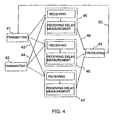
- FIG. 4 shows the operating principle of the positioning system of a BluetoothTM transmitter according to the invention.
- the system comprises transmitters 41 and 42, receivers 45, 46, 47, the locations of which are known, as well as a calculating unit 49.
- the receivers which the system has at least two, include means for receiving timing signals and for measuring the receiving delay.
- the calculating unit 49 can be either a separate unit or integrated in connection with some receiver.
- the transmitter 41 is the BluetoothTM transmitter to be positioned and 42 is the transmitter the location of which is known.
- the transmitter 42 can operate as an independent unit, which transmits at regular intervals timing signals on its own data transmission channel or it can form with the transmitter 41 a common data transmission channel, a piconetwork, whereupon they transmit data packets 43 and 44 to each other.
- the transmitters 41 and 42 are independent of each other, because the relative timing of the moments of transmitting the signals is in any case so inaccurate that it cannot be utilised in position fixing.
- the receivers 45, 46 and 47 which are independent of each other, monitor passively the data traffic of the data transmission channel or channels and make receiving delay measurements in the timing signals, which are included in the data packets 43 and 44. This can take place, for example, so that the receivers monitor the content of the header of the transmitted data packets and when detecting a transmission from the transmitter 41 or 42, they start or stop the measurement of time, for example, by the first 0-1 signal transition after the address field.
- the receivers do not have to be synchronised with each other, because the absolute moments of receiving the timing signals are of no significance to the operation of the positioning system.
- the receiving delays' measurement results 48 are transferred from the receivers to the calculating unit which, on the basis of them, determines the location co-ordinates of the transmitter 41 to be positioned. If so desired, location co-ordinates 50 can be transferred from the calculating unit over the radio path further to the BluetoothTM transmitter to be positioned.
Landscapes
- Physics & Mathematics (AREA)
- Engineering & Computer Science (AREA)
- General Physics & Mathematics (AREA)
- Radar, Positioning & Navigation (AREA)
- Remote Sensing (AREA)
- Position Fixing By Use Of Radio Waves (AREA)
Claims (10)
- Procédé pour positionner un émetteur (M), dans lequel le délai de réception des signaux de cadencement (20) d'un ou plusieurs émetteurs (R), dont les emplacements sont connus, est mesuré avec des récepteurs (A, B, C), dont les emplacements sont connus, par rapport au signal de cadencement (21) transmis par un émetteur (M) qui doit être positionné et en faisant usage de ces mesures de manière numérique, l'emplacement de l'émetteur (M), dont l'emplacement est inconnu, est déterminé, caractérisé en ce que, dans le procédé, les émetteurs et les récepteurs sont sensiblement mutuellement indépendants, en ce que, dans le procédé, au moins deux récepteurs (A, B) sont utilisés pour mesurer les délais de réception entre lesdits signaux de cadencement (20, 21) provenant de la même transmission, en ce que la mesure des délais de réception est effectuée avec la totalité des récepteurs (A, B) sensiblement au même instant, en ce que, sur la base des délais de réception, une ou plusieurs coordonnées d'emplacement de l'émetteur (M) qui doit être positionné sont calculées.
- Procédé selon la revendication 1, caractérisé en ce que, sur la base des délais de réception, les délais d'émission entre les signaux de cadencement de l'émetteur qui doit être positionné et un émetteur ou des émetteurs, dont les emplacements sont connus, sont déterminés.
- Procédé selon la revendication 2, caractérisé en ce que le procédé comprend la réception des signaux de cadencement avec deux ou plusieurs récepteurs depuis à la fois l'émetteur qui doit être positionné et l'émetteur dont l'emplacement est connu, la mesure, avec chaque récepteur, du délai de réception entre ces signaux de cadencement, le calcul, sur la base des délais de réception mesurés, des coordonnées d'emplacement non connues de l'émetteur qui doit être positionné, de même que du délai de transmission entre les signaux de cadencement des émetteurs.
- Procédé selon l'une quelconque des revendications précédentes, caractérisé en ce que comme signal de cadencement on a une impulsion, un changement de type pas ou similaire, ou un point de référence obtenu mathématiquement depuis un ensemble de transitions de signaux physiques, en ce que la détermination de l'emplacement a lieu passivement par rapport à l'émetteur qui doit être positionné, en ce qu'en utilisant un total d'au moins quatre émetteurs ou récepteurs, dont les emplacements sont connus, les coordonnées d'emplacement x et y de l'émetteur qui doit être positionné peuvent être déterminées sans tenir compte du fait que l'un quelconque du moment de transmission, du délai de propagation des signaux de cadencement des émetteurs différents, de la durée du délai de transmission entre les signaux de cadencement ni du moment de la réception des signaux de cadencement par rapport aux autres récepteurs est connu.
- Procédé selon l'une quelconque des revendications précédentes, caractérisé en ce que, dans le procédé, plus d'émetteurs et de récepteurs, dont les emplacements sont connus, sont utilisés qu'ils devraient être nécessaires pour le positionnement, sur quoi la précision du positionnement peut être accrue en résolvant les coordonnées d'emplacement non connues à l'aide de plus de systèmes d'équations.
- Système pour positionner un émetteur (M), dans lequel, avec des récepteurs (A, B, C) dont les emplacements sont connus, le délai de réception des signaux de cadencement (20) transmis par un ou plusieurs émetteurs (R), dont les emplacements sont connus, est mesuré par rapport au signal de cadencement (21) transmis par l'émetteur (M) qui doit être positionné et en faisant usage de ces mesures numériquement l'emplacement de l'émetteur (M), dont l'emplacement est inconnu, est déterminé, caractérisé en ce que les émetteurs et les récepteurs sont sensiblement indépendants les uns des autres, en ce que le système comporte au moins deux récepteurs (A, B) conçus pour mesurer les délais de réception entre lesdits signaux de cadencement (20, 21) provenant de la même transmission, en ce que la totalité des récepteurs (A, B) mesure les délais de réception sensiblement au même instant, en ce qu'une unité de calcul calcule, sur la base des délais dé réception, une ou plusieurs des coordonnées d'emplacement de l'émetteur qui doit être positionné.
- Système selon la revendication 6, caractérisé en ce que l'unité de calcul calcule, sur la base des délais de réception, les délais de transmission entre les signaux de cadencement de l'émetteur qui doit être positionné et l'émetteur ou les émetteurs dont les emplacements sont connus.
- Système selon la revendication 7, caractérisé en ce que chaque récepteur reçoit le signal de cadencement transmis par chaque émetteur, chaque récepteur mesure le délai de réception entre les signaux de cadencement, chaque récepteur transfère la valeur du délai de réception à l'unité de calcul, l'unité de calcul calcule, sur la base de paramètres connus et des délais de réception mesurés, les coordonnées d'emplacement de l'émetteur qui doit être positionné.
- Système selon la revendication 8, caractérisé en ce que l'émetteur qui doit être positionné est un émetteur radio.
- Système selon la revendication 9, caractérisé en ce que l'émetteur, dont l'emplacement est connu, et l'émetteur qui doit être positionné forment un picoréseau, en ce que le positionnement a lieu en surveillant de manière passive avec les récepteurs le trafic de données du picoréseau en question.
Applications Claiming Priority (3)
| Application Number | Priority Date | Filing Date | Title |
|---|---|---|---|
| FI992061A FI106655B (fi) | 1999-09-27 | 1999-09-27 | Menetelmä ja järjestelmä lähettimen paikantamiseksi |
| FI992061 | 1999-09-27 | ||
| PCT/FI2000/000829 WO2001023904A2 (fr) | 1999-09-27 | 2000-09-27 | Procede et systeme de positionnement d'un emetteur |
Publications (2)
| Publication Number | Publication Date |
|---|---|
| EP1222478A2 EP1222478A2 (fr) | 2002-07-17 |
| EP1222478B1 true EP1222478B1 (fr) | 2003-04-23 |
Family
ID=8555353
Family Applications (1)
| Application Number | Title | Priority Date | Filing Date |
|---|---|---|---|
| EP00960757A Expired - Lifetime EP1222478B1 (fr) | 1999-09-27 | 2000-09-27 | Procede et systeme de positionnement d'un emetteur |
Country Status (7)
| Country | Link |
|---|---|
| EP (1) | EP1222478B1 (fr) |
| JP (1) | JP2003510614A (fr) |
| CN (1) | CN1204415C (fr) |
| AU (1) | AU7295400A (fr) |
| DE (1) | DE60002358T2 (fr) |
| FI (1) | FI106655B (fr) |
| WO (1) | WO2001023904A2 (fr) |
Families Citing this family (15)
| Publication number | Priority date | Publication date | Assignee | Title |
|---|---|---|---|---|
| US6700535B2 (en) | 2001-06-01 | 2004-03-02 | Texas Instruments Incorporated | Location estimation in narrow bandwidth wireless communication systems |
| JP4223923B2 (ja) | 2003-11-06 | 2009-02-12 | 株式会社日立製作所 | 測位方式及び測位システム及び無線基地局 |
| JP2006349515A (ja) * | 2005-06-16 | 2006-12-28 | Mitsubishi Electric Corp | 変位計測システム及び変位計測方法 |
| JP4772710B2 (ja) * | 2007-02-04 | 2011-09-14 | 富士通株式会社 | 無線測位システムおよび無線測位方法 |
| JP2009210407A (ja) * | 2008-03-04 | 2009-09-17 | Mitsubishi Electric Corp | 測位装置および測位推定方法 |
| JP4382862B2 (ja) * | 2008-07-25 | 2009-12-16 | 株式会社日立製作所 | 測位方式及び測位システム及び無線基地局 |
| US20100135178A1 (en) | 2008-11-21 | 2010-06-03 | Qualcomm Incorporated | Wireless position determination using adjusted round trip time measurements |
| US8892127B2 (en) | 2008-11-21 | 2014-11-18 | Qualcomm Incorporated | Wireless-based positioning adjustments using a motion sensor |
| US9645225B2 (en) | 2008-11-21 | 2017-05-09 | Qualcomm Incorporated | Network-centric determination of node processing delay |
| US9125153B2 (en) | 2008-11-25 | 2015-09-01 | Qualcomm Incorporated | Method and apparatus for two-way ranging |
| US8768344B2 (en) | 2008-12-22 | 2014-07-01 | Qualcomm Incorporated | Post-deployment calibration for wireless position determination |
| US8750267B2 (en) | 2009-01-05 | 2014-06-10 | Qualcomm Incorporated | Detection of falsified wireless access points |
| US8781492B2 (en) | 2010-04-30 | 2014-07-15 | Qualcomm Incorporated | Device for round trip time measurements |
| EP2642311B1 (fr) * | 2012-03-21 | 2017-10-25 | Saab Medav Technologies GmbH | Procédé et appareil pour améliorer la précision des mesures dans la zone des différences de temps de déplacement de signaux |
| CN107613028A (zh) * | 2017-11-02 | 2018-01-19 | 成都吱吖科技有限公司 | 一种基于蓝牙室内定位的预加载技术 |
Family Cites Families (2)
| Publication number | Priority date | Publication date | Assignee | Title |
|---|---|---|---|---|
| US5717406A (en) * | 1995-06-07 | 1998-02-10 | Sanconix Inc. | Enhanced position calculation |
| DE69511118T2 (de) * | 1995-09-20 | 1999-11-18 | The Secretary Of State For Defence, Farnborough | Positionsbestimmung der quelle eines unbekannten signales |
-
1999
- 1999-09-27 FI FI992061A patent/FI106655B/fi active
-
2000
- 2000-09-27 CN CN 00813463 patent/CN1204415C/zh not_active Expired - Fee Related
- 2000-09-27 DE DE60002358T patent/DE60002358T2/de not_active Expired - Fee Related
- 2000-09-27 EP EP00960757A patent/EP1222478B1/fr not_active Expired - Lifetime
- 2000-09-27 AU AU72954/00A patent/AU7295400A/en not_active Abandoned
- 2000-09-27 JP JP2001527236A patent/JP2003510614A/ja not_active Withdrawn
- 2000-09-27 WO PCT/FI2000/000829 patent/WO2001023904A2/fr not_active Ceased
Also Published As
| Publication number | Publication date |
|---|---|
| DE60002358D1 (de) | 2003-05-28 |
| CN1204415C (zh) | 2005-06-01 |
| WO2001023904A2 (fr) | 2001-04-05 |
| FI106655B (fi) | 2001-03-15 |
| JP2003510614A (ja) | 2003-03-18 |
| AU7295400A (en) | 2001-04-30 |
| WO2001023904A3 (fr) | 2001-10-18 |
| EP1222478A2 (fr) | 2002-07-17 |
| CN1376268A (zh) | 2002-10-23 |
| DE60002358T2 (de) | 2004-02-26 |
Similar Documents
| Publication | Publication Date | Title |
|---|---|---|
| EP1222478B1 (fr) | Procede et systeme de positionnement d'un emetteur | |
| AU2020233659B2 (en) | Positioning system | |
| US20210149015A1 (en) | Positioning system | |
| US11061106B2 (en) | Wireless localisation system | |
| EP3455642B1 (fr) | Système de positionnement | |
| EP1014103B1 (fr) | Système pour déterminer la position | |
| US6784827B2 (en) | Determining a time of arrival of a sent signal | |
| US11102746B2 (en) | Positioning system | |
| US20090257426A1 (en) | Inserting time of departure information in frames to support multi-channel location techniques | |
| WO2001084862A2 (fr) | Etalonnage de systemes de positionnement | |
| EP1700407B1 (fr) | Compensation thermique destinee a la transmission entre des noeuds couples par un anneau de fibres unidirectionnel | |
| HK1041757B (en) | Method and system for finding mobile user position in code division multiple access communication system | |
| EP4286881A1 (fr) | Procédé et système de positionnement pour la compensation de délais de propagation interne | |
| US8441620B2 (en) | Determining distance between nodes | |
| US20220385519A1 (en) | MOBILE DEVICE FREQUENCY OFFSET DETERMINATION AND TDoA LOCALIZATION | |
| WO2018113997A1 (fr) | Procédé d'obtention de synchronisations relativement précises en vue d'une mesure d'emplacement | |
| AU2015200274B2 (en) | Wireless localisation system |
Legal Events
| Date | Code | Title | Description |
|---|---|---|---|
| PUAI | Public reference made under article 153(3) epc to a published international application that has entered the european phase |
Free format text: ORIGINAL CODE: 0009012 |
|
| 17P | Request for examination filed |
Effective date: 20020429 |
|
| AK | Designated contracting states |
Kind code of ref document: A2 Designated state(s): AT BE CH CY DE DK ES FI FR GB GR IE IT LI LU MC NL PT SE |
|
| AX | Request for extension of the european patent |
Free format text: AL;LT;LV;MK;RO;SI |
|
| R17P | Request for examination filed (corrected) |
Effective date: 20020429 |
|
| GRAH | Despatch of communication of intention to grant a patent |
Free format text: ORIGINAL CODE: EPIDOS IGRA |
|
| GRAH | Despatch of communication of intention to grant a patent |
Free format text: ORIGINAL CODE: EPIDOS IGRA |
|
| GRAA | (expected) grant |
Free format text: ORIGINAL CODE: 0009210 |
|
| AK | Designated contracting states |
Designated state(s): DE FR GB IT |
|
| REG | Reference to a national code |
Ref country code: GB Ref legal event code: FG4D |
|
| REF | Corresponds to: |
Ref document number: 60002358 Country of ref document: DE Date of ref document: 20030528 Kind code of ref document: P |
|
| REG | Reference to a national code |
Ref country code: IE Ref legal event code: FG4D |
|
| LTIE | Lt: invalidation of european patent or patent extension |
Effective date: 20030423 |
|
| ET | Fr: translation filed | ||
| PLBE | No opposition filed within time limit |
Free format text: ORIGINAL CODE: 0009261 |
|
| STAA | Information on the status of an ep patent application or granted ep patent |
Free format text: STATUS: NO OPPOSITION FILED WITHIN TIME LIMIT |
|
| 26N | No opposition filed |
Effective date: 20040126 |
|
| REG | Reference to a national code |
Ref country code: IE Ref legal event code: MM4A |
|
| PGFP | Annual fee paid to national office [announced via postgrant information from national office to epo] |
Ref country code: IT Payment date: 20060930 Year of fee payment: 7 |
|
| PGFP | Annual fee paid to national office [announced via postgrant information from national office to epo] |
Ref country code: FR Payment date: 20080915 Year of fee payment: 9 |
|
| PGFP | Annual fee paid to national office [announced via postgrant information from national office to epo] |
Ref country code: DE Payment date: 20081002 Year of fee payment: 9 |
|
| PGFP | Annual fee paid to national office [announced via postgrant information from national office to epo] |
Ref country code: GB Payment date: 20081001 Year of fee payment: 9 |
|
| PG25 | Lapsed in a contracting state [announced via postgrant information from national office to epo] |
Ref country code: IT Free format text: LAPSE BECAUSE OF NON-PAYMENT OF DUE FEES Effective date: 20070927 |
|
| GBPC | Gb: european patent ceased through non-payment of renewal fee |
Effective date: 20090927 |
|
| REG | Reference to a national code |
Ref country code: FR Ref legal event code: ST Effective date: 20100531 |
|
| PG25 | Lapsed in a contracting state [announced via postgrant information from national office to epo] |
Ref country code: FR Free format text: LAPSE BECAUSE OF NON-PAYMENT OF DUE FEES Effective date: 20090930 Ref country code: DE Free format text: LAPSE BECAUSE OF NON-PAYMENT OF DUE FEES Effective date: 20100401 |
|
| PG25 | Lapsed in a contracting state [announced via postgrant information from national office to epo] |
Ref country code: GB Free format text: LAPSE BECAUSE OF NON-PAYMENT OF DUE FEES Effective date: 20090927 |