EP1222491B1 - Bohrverfahren für optische gläser und vorrichtung zur durchführung eines derartigen verfahrens - Google Patents
Bohrverfahren für optische gläser und vorrichtung zur durchführung eines derartigen verfahrens Download PDFInfo
- Publication number
- EP1222491B1 EP1222491B1 EP00969643A EP00969643A EP1222491B1 EP 1222491 B1 EP1222491 B1 EP 1222491B1 EP 00969643 A EP00969643 A EP 00969643A EP 00969643 A EP00969643 A EP 00969643A EP 1222491 B1 EP1222491 B1 EP 1222491B1
- Authority
- EP
- European Patent Office
- Prior art keywords
- drilling
- plans
- template
- definition
- glasses
- Prior art date
- Legal status (The legal status is an assumption and is not a legal conclusion. Google has not performed a legal analysis and makes no representation as to the accuracy of the status listed.)
- Expired - Lifetime
Links
- 238000005553 drilling Methods 0.000 title claims abstract description 94
- 238000000034 method Methods 0.000 title claims abstract description 31
- 239000005304 optical glass Substances 0.000 title claims abstract description 10
- 239000011521 glass Substances 0.000 claims description 46
- 241001639412 Verres Species 0.000 description 7
- 238000004519 manufacturing process Methods 0.000 description 6
- 238000004873 anchoring Methods 0.000 description 3
- 230000000712 assembly Effects 0.000 description 1
- 238000000429 assembly Methods 0.000 description 1
- 238000012550 audit Methods 0.000 description 1
- 230000005540 biological transmission Effects 0.000 description 1
- 238000004590 computer program Methods 0.000 description 1
- 230000001186 cumulative effect Effects 0.000 description 1
- 238000012986 modification Methods 0.000 description 1
- 230000004048 modification Effects 0.000 description 1
- 230000000877 morphologic effect Effects 0.000 description 1
Images

Classifications
-
- G—PHYSICS
- G02—OPTICS
- G02C—SPECTACLES; SUNGLASSES OR GOGGLES INSOFAR AS THEY HAVE THE SAME FEATURES AS SPECTACLES; CONTACT LENSES
- G02C13/00—Assembling; Repairing; Cleaning
- G02C13/001—Assembling; Repairing
-
- G—PHYSICS
- G02—OPTICS
- G02C—SPECTACLES; SUNGLASSES OR GOGGLES INSOFAR AS THEY HAVE THE SAME FEATURES AS SPECTACLES; CONTACT LENSES
- G02C1/00—Assemblies of lenses with bridges or browbars
- G02C1/02—Bridge or browbar secured to lenses without the use of rims
Definitions
- the invention relates to the field of optics and more specifically that of eyewear.
- the invention relates to the mounting operations of the lenses on spectacle frames called "pierced frame”.
- the fixing of the branches can thus require the drilling of one, two holes or more, some of which may be notched, that is to say open on one of their sides.
- Attaching the bridge may also require drilling one, two holes or more, some of which may also be notched.
- the glasses must be pierced in areas may vary.
- the objective of the present invention is to propose a new process for drilling of cut-out lenses for the production of so-called "frame glasses” breakthrough ”which can be used with all types of glasses, all types of branches and all types of bridge connecting the glasses together.
- An additional objective is to propose such a process which can effectively take into account the morphological particularities of the person to whom are for glasses.
- Another objective of the present invention is to provide such a process which can be implemented quickly remotely.
- template virtual glasses as defining an image corresponding to a model of real clipped glass.
- the invention therefore consists in defining on a computer, using software adapted, isostatic drilling plans (i.e. defined in the absolute) to associate these drilling plans by image on a virtual glass template, then transmit this information to a machine tool consisting of a drill on which will have been placed the clipped optical glasses, drill which will pierce the glasses based on said information.
- isostatic drilling plans i.e. defined in the absolute
- the method according to the invention can be implemented on a single site.
- said definition steps drilling plans, association of these with a glass template and memorization of the corresponding information is carried out on at least one first site, said information being transmitted to at least one second site where they are transmitted to said drill.
- the stages of definition of the drilling plans, of association of the drilling plans with the virtual template of glasses, and of memorization information about drilling plans and their association with the size can easily be made by opticians in their shops ("first site”). This information can then be transmitted to a site of manufacture of spectacle frames ("second site") where they will be used for be transmitted to a drill on which we will have positioned the glasses to be drilled corresponding to the chosen template.
- first site a site of manufacture of spectacle frames
- each drilling plane is defined by relative to a point of origin O and includes an anchor A, said anchor serving as point anchoring said drilling planes on said virtual glass template.
- the drilling planes can be moved on the virtual template while remaining superimposed on it.
- connection relationship established thanks to the anchor 1 between the drilling plans and the virtual template may vary.
- the anchoring point of the anchor A will be mobile on the edge of the virtual template. We can thus move the drilling plan on this virtual template but this drilling plane will always remain at a distance predetermined edge of it.
- the anchoring plane of the anchor A may be locked in relation to one of the axes of the boxing frame of the template from the boxing center. It will thus be possible to move the drilling planes on the template virtual but these will always remain at a predetermined distance from the center boxing.
- the drilling plans will be defined for only one of the two glasses, the drilling plans relating to the other glass being automatically calculated by symmetry.
- drilling plans on computer can be carried out from many ways.
- this definition includes the definition of a diameter around the origin O cited above allowing a first hole to be made in the glass.
- the second hole in question will be a notched hole, that is, it will be open on one of the edges of the glass.
- the drilling plan correspondent will not appear in a circular form but in a oblong shape.
- the definition of the drilling plans will also include the definition of a length (L) of notched hole.
- This notched hole may also be more or less inclined.
- the definition of the drilling plans will also include the definition an angle ⁇ of inclination of the notched hole.
- said glass template is chosen in a computerized glass template library.
- said step of defining the drilling plans is carried out from standard drilling plans corresponding to mount models and stored in a computerized library of plans drilling.
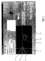
- This drilling plan includes a first hole 1 having for center the origin O and having a diameter of 1.20 millimeters.
- the drilling plan includes a second hole 2 corresponding to the drilling of a notched hole on the real glass.
- This second hole 2 has for reference a point O 'with coordinates in the coordinate system X, Y: 4 millimeters, 1 millimeter.
- This hole with a diameter of 1.20 millimeters is extended by length L of 1 millimeter to give it an oblong shape.
- the second hole having an oblong shape is not inclined relative to the X axis, that is, the angle ⁇ between this Y axis and the longitudinal axis of the second hole 2 is 0 degrees.
- the second hole 2 of oblong shape can be tilted relative to the X axis by an angle ⁇ larger or smaller.
- the drilling plan includes also an Anchor A which, in the present embodiment, presents coordinates in the XY coordinate system of: 5 millimeters, 1 millimeter.
- This anchor A is, in the context of this embodiment. a anchor point on the edge of the glass.
- the computer automatically calculates the symmetrical drilling plans for the other glass.
- the rest of the method according to the present invention consists in associating these drilling planes with a virtual lens template.
- This virtual template can be chosen from a library of templates available.
- the drilling plans defined above are associated with a glass gauge 3 whose boxing dimensions AB appear on the screen shown in the figure 2.
- Each of the bridge and nose planes includes two holes. Each plan of drilling can be moved at will on the edge of the virtual template of glasses, so that you can position the position of these drilling planes at will.
- the memorized information concerning the drilling plans and their association with the template are then transmitted to a machine tool which reproduces on real glasses the dimensions and positions of the holes defined by said drilling plans.
Landscapes
- Physics & Mathematics (AREA)
- Health & Medical Sciences (AREA)
- General Physics & Mathematics (AREA)
- Ophthalmology & Optometry (AREA)
- Optics & Photonics (AREA)
- Processing Of Stones Or Stones Resemblance Materials (AREA)
- Re-Forming, After-Treatment, Cutting And Transporting Of Glass Products (AREA)
- Eyeglasses (AREA)
- Drilling And Exploitation, And Mining Machines And Methods (AREA)
- Mounting And Adjusting Of Optical Elements (AREA)
- Laser Beam Processing (AREA)
Claims (13)
- Verfahren zum Bohren optischer Gläser mit geschliffener Umrandung zum Zweck der Herstellung von Brillen des Typs "mit gebohrtem Rahmen", bei denen die Stiele und die Brücke direkt an den Gläsern befestigt sind, wobei das Verfahren dadurch gekennzeichnet ist, dass es die folgenden Schritte umfasst:Festlegung am Rechner von mindestens einem isostatischen Bohrplan für die Stiele;Festlegung am Rechner von mindestens einem isostatischen Bohrplan zum Anbringen der Nasenbrücke an dem richtigen Platz;Zuordnung dieses Bohrplans am Rechner zu einer gegebenen virtuellen Schablone der Gläser (3) durch Überlagerung der Schablone durch die Bohrpläne;Speichern der Informationen bezüglich der Bohrpläne und ihrer Zuordnung zur virtuellen Gläserschablone;Übertragen dieser Informationen zu mindestens einer Bohrmaschine zum Durchbohren der optischen Gläser mit geschliffener Umrandung, welche der Gläserschablone entsprechen, als Funktion der Informationen.
- Verfahren nach Anspruch 1, dadurch gekennzeichnet, dass die Schritte zum Definieren der Bohrpläne, zum Zuordnen derselben zur Gläserschablone und zum Speichern der entsprechenden Informationen an mindestens einem ersten Standort erfolgen, wobei diese Informationen an mindestens einen zweiten Standort weitergeleitet werden, wo sie der Bohrmaschine zugeführt werden.
- Verfahren nach einem der Ansprüche 1 oder 2, dadurch gekennzeichnet, dass jeder Bohrplan im Verhältnis zu einem Ausgangspunkt O definiert ist und einen Anker A umfasst, wobei dieser Anker der Verankerung der Bohroläne auf der virtuellen Gläserschablone dient.
- Verfahren nach Anspruch 3, dadurch gekennzeichnet, dass der Verankerungspunkt auf dem Rand der virtuellen Gläserschablone beweglich ist.
- Verfahren nach Anspruch 3, dadurch gekennzeichnet, dass der Verankerungspunkt gegenüber einer der Achsen des Bezugspunkts des Einschlussrechtecks (boxing) der Schablone, ausgehend vom Mittelpunkt des Einschlussrechtecks, blockiert ist.
- Verfahren nach einem der Ansprüche 1 bis 5, dadurch gekennzeichnet, dass die Festlegung der Bohrpläne die Festlegung eines Durchmessers um den erwähnten Ausgangspunkt O, entsprechend einem ersten Bohrloch umfasst.
- Verfahren nach Anspruch 6, dadurch gekennzeichnet, dass die Festlegung der Bohrpläne zusätzlich noch folgendes umfasst:Festlegung der Koordinaten innerhalb eines Bezugsystems (O,X,Y) eines Mittelpunktes, der einem zweiten Loch entspricht;Festlegung eines Durchmessers des erwähnten zweiten Lochs.
- Verfahren nach Anspruch 7, dadurch gekennzeichnet, dass das erwähnte zweite Loch einen gezahnten Rand aufweist, wobei die Festlegung der Bohrpläne zudem die Festlegung einer Länge (L) des Loches mit gezahntem Rand umfasst.
- Verfahren nach Anspruch 8, dadurch gekennzeichnet, dass die Festlegung der Bohrpläne zusätzlich die Festlegung eines Neigungswinkels (α) des Lochs mit gezahntem Rand umfasst.
- Verfahren nach einem der Ansprüche 1 bis 9, dadurch gekennzeichnet, dass es im Festlegen der erwähnten Bohrpläne für nur eines der beiden Gläser besteht, gefolgt von der Berechnung der mit dem anderen Glas zusammenhängenden Bohrpläne durch Symmetrie.
- Verfahren nach einem der Ansprüche 1 bis 10, dadurch gekennzeichnet, dass die erwähnte Gläserschablone aus einer EDV Gläserschablonen-Bibliothek gewählt wird.
- Verfahren nach einem der Ansprüche 1 bis 11, dadurch gekennzeichnet, dass der erwähnte Festlegungsschritt für die Bohrpläne auf der Grundlage von Fassungsmodellen entsprechenden typischer Bohrpläne erfolgt und in einer EDV-Bohrplänen-Bibliothek gespeichert wird.
- Anwendungssystem für das Verfahren nach einem der Ansprüche 1 bis 12, welches das Durchbohren optischer Gläser mit geschliffener Umrandung zum Zweck der Herstellung von Brillen des Typs "mit gebohrtem Rahmen", bei denen die Stiele und die Brücke direkt an die Gläser befestigt sind, ermöglicht,
dadurch gekennzeichnet, dass es folgendes umfasst:Mittel zum Berechnen der isostatischen Bohrpläne für die Stiele und zum Positionieren der Nasenbrücke;Mittel zum Zuordnen dieser Bohrpläne zu einer gegebenen virtuellen Gläserschablone (3);Speichermittel der Informationen bezüglich der Bohrpläne und ihrer Zuordnungen zu der erwähnten virtuellen Gläserschablone;Mittel zum Übertragen dieser Informationen an mindestens eine Bohrmaschine;mindestens eine Bohrmaschine zum Bohren der erwähnten Gläser mit geschliffenen Rändern, als Funktion dieser Informationen.
Applications Claiming Priority (3)
| Application Number | Priority Date | Filing Date | Title |
|---|---|---|---|
| FR9913314 | 1999-10-20 | ||
| FR9913314A FR2800172B1 (fr) | 1999-10-20 | 1999-10-20 | Procede de percage de verres optiques et systeme pour la mise en oeuvre d'un tel procede |
| PCT/FR2000/002907 WO2001029609A1 (fr) | 1999-10-20 | 2000-10-18 | Procede de perçage de verres optiques et systeme pour la mise en oeuvre d'un tel procede |
Publications (2)
| Publication Number | Publication Date |
|---|---|
| EP1222491A1 EP1222491A1 (de) | 2002-07-17 |
| EP1222491B1 true EP1222491B1 (de) | 2003-05-28 |
Family
ID=9551325
Family Applications (1)
| Application Number | Title | Priority Date | Filing Date |
|---|---|---|---|
| EP00969643A Expired - Lifetime EP1222491B1 (de) | 1999-10-20 | 2000-10-18 | Bohrverfahren für optische gläser und vorrichtung zur durchführung eines derartigen verfahrens |
Country Status (6)
| Country | Link |
|---|---|
| EP (1) | EP1222491B1 (de) |
| AT (1) | ATE241816T1 (de) |
| AU (1) | AU7931100A (de) |
| DE (1) | DE60003060T2 (de) |
| FR (1) | FR2800172B1 (de) |
| WO (1) | WO2001029609A1 (de) |
Families Citing this family (2)
| Publication number | Priority date | Publication date | Assignee | Title |
|---|---|---|---|---|
| FR2865046B1 (fr) * | 2004-01-08 | 2006-03-10 | Frederic Dupuy | Dispositif pour le percage de verres et la finition des vis d'assemblage et son procede associe |
| JP5085898B2 (ja) * | 2006-07-31 | 2012-11-28 | 株式会社ニデック | 眼鏡レンズ加工装置 |
Family Cites Families (7)
| Publication number | Priority date | Publication date | Assignee | Title |
|---|---|---|---|---|
| DE3318897C2 (de) * | 1983-05-25 | 1986-03-06 | Optische Werke G. Rodenstock, 8000 Muenchen | Bohrlehre für Brillengläser |
| US5257198A (en) * | 1991-12-18 | 1993-10-26 | Schoyck Carol G Van | Method of transmitting edger information to a remote numerically controlled edger |
| WO1994004957A1 (en) * | 1992-08-17 | 1994-03-03 | Jan Houmand | Marking jig for spectacle lenses |
| DE9304045U1 (de) * | 1993-03-19 | 1994-02-17 | J. Hoffmann exklusive Brillenfertigung GmbH, 53539 Kelberg | Bohrhilfe für Glasbrillen |
| DE4438634A1 (de) * | 1994-10-28 | 1996-05-09 | Rodenstock Optik G | Brillenglasbohrschablone |
| DE19642171A1 (de) * | 1996-10-12 | 1998-04-30 | Wernicke & Co Gmbh | Verfahren zum Ermitteln und Übertragen von Umfangsdaten eines formzuschleifenden Brillenglases |
| DE19749631C2 (de) * | 1997-11-11 | 1999-10-14 | Rodenstock Optik G | Schablone für ein Brillenglas |
-
1999
- 1999-10-20 FR FR9913314A patent/FR2800172B1/fr not_active Expired - Fee Related
-
2000
- 2000-10-18 AU AU79311/00A patent/AU7931100A/en not_active Abandoned
- 2000-10-18 WO PCT/FR2000/002907 patent/WO2001029609A1/fr not_active Ceased
- 2000-10-18 AT AT00969643T patent/ATE241816T1/de not_active IP Right Cessation
- 2000-10-18 EP EP00969643A patent/EP1222491B1/de not_active Expired - Lifetime
- 2000-10-18 DE DE60003060T patent/DE60003060T2/de not_active Expired - Fee Related
Also Published As
| Publication number | Publication date |
|---|---|
| AU7931100A (en) | 2001-04-30 |
| DE60003060D1 (de) | 2003-07-03 |
| DE60003060T2 (de) | 2004-04-08 |
| EP1222491A1 (de) | 2002-07-17 |
| FR2800172A1 (fr) | 2001-04-27 |
| WO2001029609A1 (fr) | 2001-04-26 |
| ATE241816T1 (de) | 2003-06-15 |
| FR2800172B1 (fr) | 2001-12-21 |
Similar Documents
| Publication | Publication Date | Title |
|---|---|---|
| CA2399247A1 (en) | Method and system for prescribing and/or dispensing ophthalmic lenses | |
| WO2015101737A1 (fr) | Procédé de détermination d'au moins un paramètre géométrique d'une monture personnalisée de lunettes et procédé de détermination de la monture personnalisée associé | |
| CA2884576A1 (fr) | Procede et dispositif pour preparer une monture de lunettes | |
| EP3090307A1 (de) | Verfahren zur bestimmung einer geometrischen definition einer individuell angepassten optischen vorrichtung | |
| EP2091690B9 (de) | Verfahren zur bestimmung der position eines in einem brillenglas zu erzeugenden bohrlochs | |
| EP2150375B1 (de) | Konturfräsverfahren für brillengläser mittels ablesen und aktualisierung eines datenbankregisters für linsen und/oder fassungen | |
| FR3010802A1 (fr) | Procede d'acquisition et de mesure de donnees geometriques d'un verre de demonstration adapte a une monture de lunettes | |
| EP1222491A1 (de) | Bohrverfahren für optische gläser und vorrichtung zur durchführung eines derartigen verfahrens | |
| FR3013620A1 (fr) | Procede de biseautage d'une lentille ophtalmique | |
| US10247961B2 (en) | Method of locally thickening an ophthalmic lens | |
| CA2388725A1 (en) | Visual aid for directing light onto an optically responsive portion of an eye | |
| EP4116762B1 (de) | Vorrichtung zur unterstützung der herstellung eines endgültigen korrekturlinsenglases und entsprechendes verfahren | |
| EP1866694A1 (de) | Verfahren zum zentrieren einer brillenlinse an einem randlosen rahmen | |
| US8128462B2 (en) | Method of centering a non-edged ophthalmic lens in which the centering point of the lens is offset relative to its geometric center | |
| WO2010106275A1 (fr) | Procede de decoupe d'une pastille a appliquer sur un substrat courbe | |
| FR2918770A1 (fr) | Afficheur destine a etre integre a une paire de lunettes. | |
| WO1999026759A1 (fr) | Procede de retouche de verre de lunettes, et dispositif associe | |
| FR2929722A1 (fr) | Procede de decoupe de filtres solaires | |
| WO2004053565A3 (en) | Frame and lens system | |
| FR3124069A1 (fr) | Procédé d’essayage de lunettes virtuelles | |
| KR200272434Y1 (ko) | 가공용 통공이 뚫린 모조렌즈 | |
| FR3080925A1 (fr) | Dispositif de correction oculaire temporaire pendant l'essayage d'une monture de lunettes chez un opticien | |
| JPH11143920A (ja) | 眼鏡フレーム製造データの作成方法 | |
| JP2000047142A (ja) | 縁無し眼鏡のレンズ取付構造 | |
| EP1882207A1 (de) | Verfahren zum aufzeichnen von geometrischen kenngrössen einer zweiten linse mittels abtasten einer ersten linse, wobei beide linsen aus derselben charge stammen |
Legal Events
| Date | Code | Title | Description |
|---|---|---|---|
| PUAI | Public reference made under article 153(3) epc to a published international application that has entered the european phase |
Free format text: ORIGINAL CODE: 0009012 |
|
| 17P | Request for examination filed |
Effective date: 20020417 |
|
| AK | Designated contracting states |
Kind code of ref document: A1 Designated state(s): AT BE CH CY DE DK ES FI FR GB GR IE IT LI LU MC NL PT SE |
|
| AX | Request for extension of the european patent |
Free format text: AL;LT;LV;MK;RO;SI |
|
| GRAH | Despatch of communication of intention to grant a patent |
Free format text: ORIGINAL CODE: EPIDOS IGRA |
|
| GRAH | Despatch of communication of intention to grant a patent |
Free format text: ORIGINAL CODE: EPIDOS IGRA |
|
| GRAA | (expected) grant |
Free format text: ORIGINAL CODE: 0009210 |
|
| AK | Designated contracting states |
Designated state(s): AT BE CH CY DE DK ES FI FR GB GR IE IT LI LU MC NL PT SE |
|
| PG25 | Lapsed in a contracting state [announced via postgrant information from national office to epo] |
Ref country code: IT Free format text: LAPSE BECAUSE OF FAILURE TO SUBMIT A TRANSLATION OF THE DESCRIPTION OR TO PAY THE FEE WITHIN THE PRESCRIBED TIME-LIMIT;WARNING: LAPSES OF ITALIAN PATENTS WITH EFFECTIVE DATE BEFORE 2007 MAY HAVE OCCURRED AT ANY TIME BEFORE 2007. THE CORRECT EFFECTIVE DATE MAY BE DIFFERENT FROM THE ONE RECORDED. Effective date: 20030528 Ref country code: FI Free format text: LAPSE BECAUSE OF FAILURE TO SUBMIT A TRANSLATION OF THE DESCRIPTION OR TO PAY THE FEE WITHIN THE PRESCRIBED TIME-LIMIT Effective date: 20030528 Ref country code: NL Free format text: LAPSE BECAUSE OF FAILURE TO SUBMIT A TRANSLATION OF THE DESCRIPTION OR TO PAY THE FEE WITHIN THE PRESCRIBED TIME-LIMIT Effective date: 20030528 Ref country code: IE Free format text: LAPSE BECAUSE OF FAILURE TO SUBMIT A TRANSLATION OF THE DESCRIPTION OR TO PAY THE FEE WITHIN THE PRESCRIBED TIME-LIMIT Effective date: 20030528 Ref country code: AT Free format text: LAPSE BECAUSE OF FAILURE TO SUBMIT A TRANSLATION OF THE DESCRIPTION OR TO PAY THE FEE WITHIN THE PRESCRIBED TIME-LIMIT Effective date: 20030528 |
|
| REG | Reference to a national code |
Ref country code: GB Ref legal event code: FG4D Free format text: NOT ENGLISH |
|
| REG | Reference to a national code |
Ref country code: CH Ref legal event code: EP |
|
| REG | Reference to a national code |
Ref country code: IE Ref legal event code: FG4D Free format text: FRENCH |
|
| REF | Corresponds to: |
Ref document number: 60003060 Country of ref document: DE Date of ref document: 20030703 Kind code of ref document: P |
|
| PG25 | Lapsed in a contracting state [announced via postgrant information from national office to epo] |
Ref country code: GR Free format text: LAPSE BECAUSE OF FAILURE TO SUBMIT A TRANSLATION OF THE DESCRIPTION OR TO PAY THE FEE WITHIN THE PRESCRIBED TIME-LIMIT Effective date: 20030828 Ref country code: PT Free format text: LAPSE BECAUSE OF FAILURE TO SUBMIT A TRANSLATION OF THE DESCRIPTION OR TO PAY THE FEE WITHIN THE PRESCRIBED TIME-LIMIT Effective date: 20030828 Ref country code: DK Free format text: LAPSE BECAUSE OF FAILURE TO SUBMIT A TRANSLATION OF THE DESCRIPTION OR TO PAY THE FEE WITHIN THE PRESCRIBED TIME-LIMIT Effective date: 20030828 Ref country code: SE Free format text: LAPSE BECAUSE OF FAILURE TO SUBMIT A TRANSLATION OF THE DESCRIPTION OR TO PAY THE FEE WITHIN THE PRESCRIBED TIME-LIMIT Effective date: 20030828 |
|
| PG25 | Lapsed in a contracting state [announced via postgrant information from national office to epo] |
Ref country code: ES Free format text: LAPSE BECAUSE OF FAILURE TO SUBMIT A TRANSLATION OF THE DESCRIPTION OR TO PAY THE FEE WITHIN THE PRESCRIBED TIME-LIMIT Effective date: 20030908 |
|
| GBT | Gb: translation of ep patent filed (gb section 77(6)(a)/1977) | ||
| PG25 | Lapsed in a contracting state [announced via postgrant information from national office to epo] |
Ref country code: CY Free format text: LAPSE BECAUSE OF FAILURE TO SUBMIT A TRANSLATION OF THE DESCRIPTION OR TO PAY THE FEE WITHIN THE PRESCRIBED TIME-LIMIT Effective date: 20031018 Ref country code: LU Free format text: LAPSE BECAUSE OF NON-PAYMENT OF DUE FEES Effective date: 20031018 |
|
| PG25 | Lapsed in a contracting state [announced via postgrant information from national office to epo] |
Ref country code: MC Free format text: LAPSE BECAUSE OF NON-PAYMENT OF DUE FEES Effective date: 20031031 Ref country code: BE Free format text: LAPSE BECAUSE OF NON-PAYMENT OF DUE FEES Effective date: 20031031 |
|
| NLV1 | Nl: lapsed or annulled due to failure to fulfill the requirements of art. 29p and 29m of the patents act | ||
| LTIE | Lt: invalidation of european patent or patent extension |
Effective date: 20030528 |
|
| REG | Reference to a national code |
Ref country code: IE Ref legal event code: FD4D |
|
| PLBE | No opposition filed within time limit |
Free format text: ORIGINAL CODE: 0009261 |
|
| STAA | Information on the status of an ep patent application or granted ep patent |
Free format text: STATUS: NO OPPOSITION FILED WITHIN TIME LIMIT |
|
| BERE | Be: lapsed |
Owner name: *JACQUES DENIS EXPORT Effective date: 20031031 |
|
| 26N | No opposition filed |
Effective date: 20040302 |
|
| PG25 | Lapsed in a contracting state [announced via postgrant information from national office to epo] |
Ref country code: LI Free format text: LAPSE BECAUSE OF NON-PAYMENT OF DUE FEES Effective date: 20041031 Ref country code: CH Free format text: LAPSE BECAUSE OF NON-PAYMENT OF DUE FEES Effective date: 20041031 |
|
| REG | Reference to a national code |
Ref country code: CH Ref legal event code: PL |
|
| REG | Reference to a national code |
Ref country code: GB Ref legal event code: 732E |
|
| REG | Reference to a national code |
Ref country code: FR Ref legal event code: CD |
|
| REG | Reference to a national code |
Ref country code: FR Ref legal event code: TP Ref country code: FR Ref legal event code: RM Ref country code: FR Ref legal event code: CD |
|
| PGFP | Annual fee paid to national office [announced via postgrant information from national office to epo] |
Ref country code: DE Payment date: 20071114 Year of fee payment: 8 |
|
| PGFP | Annual fee paid to national office [announced via postgrant information from national office to epo] |
Ref country code: FR Payment date: 20071017 Year of fee payment: 8 Ref country code: GB Payment date: 20071031 Year of fee payment: 8 |
|
| REG | Reference to a national code |
Ref country code: GB Ref legal event code: 732E |
|
| GBPC | Gb: european patent ceased through non-payment of renewal fee |
Effective date: 20081018 |
|
| REG | Reference to a national code |
Ref country code: FR Ref legal event code: ST Effective date: 20090630 |
|
| PG25 | Lapsed in a contracting state [announced via postgrant information from national office to epo] |
Ref country code: DE Free format text: LAPSE BECAUSE OF NON-PAYMENT OF DUE FEES Effective date: 20090501 |
|
| PG25 | Lapsed in a contracting state [announced via postgrant information from national office to epo] |
Ref country code: FR Free format text: LAPSE BECAUSE OF NON-PAYMENT OF DUE FEES Effective date: 20081031 |
|
| PG25 | Lapsed in a contracting state [announced via postgrant information from national office to epo] |
Ref country code: GB Free format text: LAPSE BECAUSE OF NON-PAYMENT OF DUE FEES Effective date: 20081018 |