EP1222723B1 - Kabelverbindungen sowie kabelendverschlüsse - Google Patents
Kabelverbindungen sowie kabelendverschlüsse Download PDFInfo
- Publication number
- EP1222723B1 EP1222723B1 EP00973461A EP00973461A EP1222723B1 EP 1222723 B1 EP1222723 B1 EP 1222723B1 EP 00973461 A EP00973461 A EP 00973461A EP 00973461 A EP00973461 A EP 00973461A EP 1222723 B1 EP1222723 B1 EP 1222723B1
- Authority
- EP
- European Patent Office
- Prior art keywords
- cable
- flow
- conduit
- connector
- cavity
- Prior art date
- Legal status (The legal status is an assumption and is not a legal conclusion. Google has not performed a legal analysis and makes no representation as to the accuracy of the status listed.)
- Expired - Lifetime
Links
- 238000000034 method Methods 0.000 claims abstract description 76
- 239000000463 material Substances 0.000 claims abstract description 60
- 239000012530 fluid Substances 0.000 claims abstract description 39
- 238000002788 crimping Methods 0.000 claims abstract description 8
- 238000009413 insulation Methods 0.000 claims description 37
- 238000004891 communication Methods 0.000 claims description 34
- 238000005304 joining Methods 0.000 claims description 8
- 229910000831 Steel Inorganic materials 0.000 claims description 4
- 239000010959 steel Substances 0.000 claims description 4
- 239000011810 insulating material Substances 0.000 claims 11
- 239000007769 metal material Substances 0.000 claims 2
- 238000002347 injection Methods 0.000 description 32
- 239000007924 injection Substances 0.000 description 32
- 239000004020 conductor Substances 0.000 description 29
- 239000007789 gas Substances 0.000 description 14
- 238000013461 design Methods 0.000 description 13
- 238000010276 construction Methods 0.000 description 9
- 240000005572 Syzygium cordatum Species 0.000 description 8
- 235000006650 Syzygium cordatum Nutrition 0.000 description 8
- XLYOFNOQVPJJNP-UHFFFAOYSA-N water Substances O XLYOFNOQVPJJNP-UHFFFAOYSA-N 0.000 description 7
- 150000001875 compounds Chemical class 0.000 description 6
- 230000007935 neutral effect Effects 0.000 description 6
- RYGMFSIKBFXOCR-UHFFFAOYSA-N Copper Chemical compound [Cu] RYGMFSIKBFXOCR-UHFFFAOYSA-N 0.000 description 5
- 239000000853 adhesive Substances 0.000 description 5
- 230000001070 adhesive effect Effects 0.000 description 5
- 230000006835 compression Effects 0.000 description 5
- 238000007906 compression Methods 0.000 description 5
- 239000000356 contaminant Substances 0.000 description 5
- 229910052802 copper Inorganic materials 0.000 description 5
- 239000010949 copper Substances 0.000 description 5
- 238000009434 installation Methods 0.000 description 5
- 239000007788 liquid Substances 0.000 description 5
- 229910052751 metal Inorganic materials 0.000 description 5
- 239000002184 metal Substances 0.000 description 5
- IJGRMHOSHXDMSA-UHFFFAOYSA-N Atomic nitrogen Chemical compound N#N IJGRMHOSHXDMSA-UHFFFAOYSA-N 0.000 description 4
- 229910052782 aluminium Inorganic materials 0.000 description 4
- XAGFODPZIPBFFR-UHFFFAOYSA-N aluminium Chemical compound [Al] XAGFODPZIPBFFR-UHFFFAOYSA-N 0.000 description 4
- 230000007246 mechanism Effects 0.000 description 4
- 238000012546 transfer Methods 0.000 description 4
- 239000004698 Polyethylene Substances 0.000 description 3
- 230000000712 assembly Effects 0.000 description 3
- 238000000429 assembly Methods 0.000 description 3
- 230000003287 optical effect Effects 0.000 description 3
- 239000004033 plastic Substances 0.000 description 3
- 229920003023 plastic Polymers 0.000 description 3
- -1 polyethylene Polymers 0.000 description 3
- 229920000573 polyethylene Polymers 0.000 description 3
- 229920000642 polymer Polymers 0.000 description 3
- 230000008569 process Effects 0.000 description 3
- 229920000181 Ethylene propylene rubber Polymers 0.000 description 2
- 239000004705 High-molecular-weight polyethylene Substances 0.000 description 2
- 239000004677 Nylon Substances 0.000 description 2
- ATUOYWHBWRKTHZ-UHFFFAOYSA-N Propane Chemical compound CCC ATUOYWHBWRKTHZ-UHFFFAOYSA-N 0.000 description 2
- 239000003963 antioxidant agent Substances 0.000 description 2
- 238000013459 approach Methods 0.000 description 2
- 239000000805 composite resin Substances 0.000 description 2
- 229920003020 cross-linked polyethylene Polymers 0.000 description 2
- 239000004703 cross-linked polyethylene Substances 0.000 description 2
- 239000003989 dielectric material Substances 0.000 description 2
- 239000013536 elastomeric material Substances 0.000 description 2
- 239000000835 fiber Substances 0.000 description 2
- 150000002500 ions Chemical class 0.000 description 2
- VNWKTOKETHGBQD-UHFFFAOYSA-N methane Chemical compound C VNWKTOKETHGBQD-UHFFFAOYSA-N 0.000 description 2
- 239000000203 mixture Substances 0.000 description 2
- 229910052757 nitrogen Inorganic materials 0.000 description 2
- 229920001778 nylon Polymers 0.000 description 2
- 230000001681 protective effect Effects 0.000 description 2
- 239000000700 radioactive tracer Substances 0.000 description 2
- 239000000243 solution Substances 0.000 description 2
- OTMSDBZUPAUEDD-UHFFFAOYSA-N Ethane Chemical compound CC OTMSDBZUPAUEDD-UHFFFAOYSA-N 0.000 description 1
- 229920000271 Kevlar® Polymers 0.000 description 1
- 229920002367 Polyisobutene Polymers 0.000 description 1
- 239000004809 Teflon Substances 0.000 description 1
- 229920006362 Teflon® Polymers 0.000 description 1
- 239000012963 UV stabilizer Substances 0.000 description 1
- 150000001298 alcohols Chemical class 0.000 description 1
- 238000004873 anchoring Methods 0.000 description 1
- 235000006708 antioxidants Nutrition 0.000 description 1
- 230000009286 beneficial effect Effects 0.000 description 1
- 230000005540 biological transmission Effects 0.000 description 1
- 239000001273 butane Substances 0.000 description 1
- 239000012159 carrier gas Substances 0.000 description 1
- 229910010293 ceramic material Inorganic materials 0.000 description 1
- 238000011109 contamination Methods 0.000 description 1
- 238000005260 corrosion Methods 0.000 description 1
- 230000007797 corrosion Effects 0.000 description 1
- 230000008878 coupling Effects 0.000 description 1
- 238000010168 coupling process Methods 0.000 description 1
- 238000005859 coupling reaction Methods 0.000 description 1
- 238000005520 cutting process Methods 0.000 description 1
- 239000002274 desiccant Substances 0.000 description 1
- CVQVSVBUMVSJES-UHFFFAOYSA-N dimethoxy-methyl-phenylsilane Chemical compound CO[Si](C)(OC)C1=CC=CC=C1 CVQVSVBUMVSJES-UHFFFAOYSA-N 0.000 description 1
- 230000002708 enhancing effect Effects 0.000 description 1
- 125000001301 ethoxy group Chemical group [H]C([H])([H])C([H])([H])O* 0.000 description 1
- 239000000945 filler Substances 0.000 description 1
- 239000001307 helium Substances 0.000 description 1
- 229910052734 helium Inorganic materials 0.000 description 1
- SWQJXJOGLNCZEY-UHFFFAOYSA-N helium atom Chemical compound [He] SWQJXJOGLNCZEY-UHFFFAOYSA-N 0.000 description 1
- GPRLSGONYQIRFK-UHFFFAOYSA-N hydron Chemical compound [H+] GPRLSGONYQIRFK-UHFFFAOYSA-N 0.000 description 1
- 239000003112 inhibitor Substances 0.000 description 1
- 239000012212 insulator Substances 0.000 description 1
- 239000004761 kevlar Substances 0.000 description 1
- 239000012528 membrane Substances 0.000 description 1
- 150000002739 metals Chemical class 0.000 description 1
- IJDNQMDRQITEOD-UHFFFAOYSA-N n-butane Chemical compound CCCC IJDNQMDRQITEOD-UHFFFAOYSA-N 0.000 description 1
- OFBQJSOFQDEBGM-UHFFFAOYSA-N n-pentane Natural products CCCCC OFBQJSOFQDEBGM-UHFFFAOYSA-N 0.000 description 1
- 239000004014 plasticizer Substances 0.000 description 1
- 239000001294 propane Substances 0.000 description 1
- 125000002572 propoxy group Chemical group [*]OC([H])([H])C(C([H])([H])[H])([H])[H] 0.000 description 1
- 230000003716 rejuvenation Effects 0.000 description 1
- 239000000565 sealant Substances 0.000 description 1
- 239000003566 sealing material Substances 0.000 description 1
- 238000000926 separation method Methods 0.000 description 1
- 239000007787 solid Substances 0.000 description 1
- 239000002904 solvent Substances 0.000 description 1
- 238000003860 storage Methods 0.000 description 1
- 239000000126 substance Substances 0.000 description 1
- SFZCNBIFKDRMGX-UHFFFAOYSA-N sulfur hexafluoride Chemical compound FS(F)(F)(F)(F)F SFZCNBIFKDRMGX-UHFFFAOYSA-N 0.000 description 1
- BFKJFAAPBSQJPD-UHFFFAOYSA-N tetrafluoroethene Chemical compound FC(F)=C(F)F BFKJFAAPBSQJPD-UHFFFAOYSA-N 0.000 description 1
- 238000003466 welding Methods 0.000 description 1
Images


Classifications
-
- H—ELECTRICITY
- H02—GENERATION; CONVERSION OR DISTRIBUTION OF ELECTRIC POWER
- H02G—INSTALLATION OF ELECTRIC CABLES OR LINES, OR OF COMBINED OPTICAL AND ELECTRIC CABLES OR LINES
- H02G15/00—Cable fittings
- H02G15/20—Cable fittings for cables filled with or surrounded by gas or oil
- H02G15/24—Cable junctions
-
- H—ELECTRICITY
- H01—ELECTRIC ELEMENTS
- H01B—CABLES; CONDUCTORS; INSULATORS; SELECTION OF MATERIALS FOR THEIR CONDUCTIVE, INSULATING OR DIELECTRIC PROPERTIES
- H01B7/00—Insulated conductors or cables characterised by their form
- H01B7/17—Protection against damage caused by external factors, e.g. sheaths or armouring
- H01B7/28—Protection against damage caused by moisture, corrosion, chemical attack or weather
- H01B7/2813—Protection against damage caused by electrical, chemical or water tree deterioration
-
- H—ELECTRICITY
- H02—GENERATION; CONVERSION OR DISTRIBUTION OF ELECTRIC POWER
- H02G—INSTALLATION OF ELECTRIC CABLES OR LINES, OR OF COMBINED OPTICAL AND ELECTRIC CABLES OR LINES
- H02G15/00—Cable fittings
- H02G15/20—Cable fittings for cables filled with or surrounded by gas or oil
- H02G15/26—Expansion vessels; Locking heads; Auxiliary pipe-lines
Definitions
- the present invention relates generally to cable connectors and terminators, more particularly, to connectors and terminators for flow-through cables.
- Typical underground electrical cables include a number of copper or aluminum strands surrounded by a semiconducting or insulating strand shield, a layer of insulation, and an insulation shield. This design of underground cables is known for having a useful life of25-40 years. In some instances, the life span of an underground cable is shortened when water enters the cable and forms micro-voids in the insulation. These micro-voids spread throughout insulation in a tree like shape, these collections of micro-voids are also called water trees.
- Water trees are formed in the insulation when medium to high voltage alternating current is applied to a polymeric dielectric (insulator) in the presence of water and ions. As water trees grow, they compromise the dielectric properties of the polymer until the insulation fails. Many large water trees initiate at the site of an imperfection or a contaminant, but contamination is not a necessary condition for water trees to propagate.
- Water tree growth can be eliminated or retarded by removing or minimizing the water or ions, or by reducing the voltage stress.
- Another approach requires the injection of dielectric enhancement fluid into interstices located between the strands of cables.
- Certain cables may include at least one dedicated conduit to aid the injection of a dielectric enhancement fluid into the interstices between the strands of cables.
- the fluid reacts with water inside the cable and oligomerizes to form a fluid with dielectric enhancement properties.
- the oligomerized fluid functions as a water tree retardant and provides other beneficial properties.
- Flow-through cables having a dedicated conduit to enhance the flow of the dielectric fluid through the length of the cable advance this injection technique.
- fluidic transfer capability means having the capability to transfer both gas and liquid.
- traditional methods do not protect the conduits in the cable from contaminants during installation.
- the present invention relates to methods and apparatuses for connecting flow-through cables.
- Flow-through cables have a conduit or a plurality of conduits longitudinally placed inside the cable to allow fluid passage. More specifically, the present invention provides several embodiments of joints and terminators for connecting and anchoring flow-through cables.
- the joints and terminators of the present invention provide electrical or optical communication in a conductor as well as a flow path that allows fluid to flow through the cable without leaking.
- a method for connecting two flow-through cables includes inserting a tubing material into the conduit of one flow-through cable, placing a crimp connector over the cable's conductive core and crimping the crimp connector. The tubing material is then placed into the conduit of the second flow-through cable, the cables are aligned, and then the crimp connector is fastened to the conductive core of the second flow-through cable.
- the termination assembly includes a rigid tubing material, a hollowed plug assembly that includes a single or a plurality of rigid tubes, a tubing connector connected to the single or plurality of rigid tubes, and a conductive terminator that has a cavity adapted to anchor a cable's conductive core and allow a flexible tubing material to attach to the single or plurality of rigid tubes while being routed through the conductive terminator.
- the method for joining two flow-through cables includes the splicing method, as describe above, utilizing a two-part connector.
- the tubing material is inserted into the conduit of the first flow-through cable and then withdrawn from the first cable as it is fed into the joining flow-through cable.
- the two-part connector is fastened to the conductive cores either one piece at a time, or together after the two conductive cores are joined.
- the present invention provides efficient solutions for injecting a dielectric enhancing substance into flow-through cables.
- the devices and methods of the present invention allow an operator to achieve fluid and gas injections into flow-through cables without the need to remove the cable from an attached terminator or connector.
- the designs provide safe injection access to the cable conduit even while the cable is energized with an electrical charge.
- the terminators and connectors of the present invention also allow for perpetual rejuvenation of the flow-through cables.
- a flow-through cable can be repeatedly or continuously injected over the lifetime of the cable.
- the present invention provides several mechanisms that allow an operator to inject flow-through cables using a high injection pressure without a high risk of fluid or gas leakage.
- the design of the connectors and terminators allow the injection pressure to operate up to the maximum pressure of the flow-through cable conduit.
- the present invention provides economical and efficient methods of cable connection and termination.
- the methods and devices in the present invention protect the conduit from contaminants during the installation. Further, the methods and devices of the present invention prevent the conduit from rupturing or collapsing.
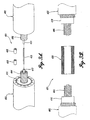
- FIGURES 1 and 2 illustrate a flow-through cable for transmitting information (hereinafter "cable 400").
- the cable 400 includes a jacket 22, an insulation layer 416, a conductive core 404, and a conduit 412.
- the cable 400 illustrated in FIGURES 1-2 is illustrated as a multiple conductive strand, 1/0-power cable, such as a medium voltage cable that carries between 5,000 and 35,000 volts.
- a power cable is illustrated in this example, it should be apparent that the flow-through cable design may be applied to other uses, such as low voltage power cables, transmission voltage power cables, control cables, and communication cables including conductive pair, telephone, and digital communication.
- a cable for transmitting information includes not only electric cables, but also light transmitting cables.
- the jacket 22 is suitably an elongate tubular member formed from a polyethylene material, PVC, or other polymers known in the art.
- a plurality of longitudinally extending conductive neutral wires 30 are embedded within and extend the length of the jacket 22.
- a total of 15 conductive neutral wires 30 are disposed circumferentially around the insulation layer 416.
- the insulation layer 416 is suitably formed from a high molecular weight polyethylene (HMWPE) polymer, a cross-linked polyethylene (XLPE), an ethylenepropylene rubber (EPR) or other solid dielectrics, wherein each may include water tree retardants, fillers, anti-oxidants, UV stabilizers, etc.
- the insulation layer 416 is coaxially disposed within the jacket 22 and extends the length of the jacket 22.
- Disposed around the perimeter of the insulation layer 416 is an insulation shield 32.
- the insulation shield 32 is suitably formed from a compound that includes polyethylene or a similar material and extends the length of the jacket 22.
- the insulation shield 32 is disposed between the outside perimeter of the insulation layer 416 and the plurality of conductive neutral wires 30.
- the conductive core 404 is coaxially received within the insulation layer 416 and is centrally located therein.
- the conductive core 404 is surrounded by a semiconductive or insulating strand shield 34.
- the strand shield 34 is suitably formed from a compound that includes polyethylene or a similar material and surrounds the conductive core 404, such that it is disposed between the conductive core 404 and the insulation layer 416.
- the conductive core 404 includes a plurality of electrically conductive strands 36.
- the conductive core 404 may also be made from a single conductive strand of metal.
- the strands 36 are formed from a copper, aluminum, or other conductive material.
- a conductive core 404 is generally made of several wound strands, ranging from 7 to 61 strands in one cable.
- the conductive core 404 illustrated in FIGURES I and 2 is has a total of 18 wound strands.
- the conduit 412 is formed from a chemically permeable material, such as plastics, sintered metals or fiber resin composites in plastic. Suitable plastics include TEFLON ® , and NYLON ® . Suitable fiber resin composites include KEVLAR ® .
- the conduit 412 has sufficient physical strength to be incorporated in the stranding operation and sufficient thermal properties for use in maximum and minimum thermal environments in which the cable 400 may be manufactured or used. Preferably, the conduit 412 has the thinnest wall possible to allow compound storage and free flow, is permeable, and can withstand operating and emergency overload design temperatures of 130°C or greater.
- the wall thickness of the conduit 412 is suitably between 0.40 mm and 0.79 mm (1/64 and 1/32 of an inch).
- a cylindrical or nearly cylindrical geometry is the preferred geometry for the conduit 412, it should be apparent that other hollow geometries are also included within the scope of the present invention.
- the conduit 412 As received within the conductive core 404, the conduit 412 provides a centrally located, unobstructed and longitudinally extending conduit through the length of the cable 400.
- the conduit 412 is adapted to permit a liquid or gas compound to flow therethrough.
- the conduit 412 carries an insulation restoration fluid, such as CABLECURE ® /XL, a mixture of phenylmethyldimethoxysilane fluid together with other components or ethoxy or propoxy equivalents.
- insulation restoration fluids are injected into the conduit 412 and diffuse through the permeable material of the conduit 412 and into the insulation to increase the dielectric properties of the insulation, as described in greater detail below.
- the conduit 412 may also carry a gas or desiccant liquid through the length of the cable 400 to keep the cable 400 dry by removing water or other permeable contaminants.
- gas or liquids include dry nitrogen, dry air, dry SF6, anhydrous alcohols, or other anhydrous organic liquids that are mutually soluble with water.
- the conduit 412 may be injected with a tracer fluid to aid in the identification of a fault or hole in the cable 400.
- such tracer fluids include, in pure forms or mixtures, helium, SF6, methane, ethane, propane, butane or any other gas that is detectable with a hydrogen ion detector or a carrier gas, such as nitrogen and a mercaptin.
- a hydrogen ion detector or a carrier gas such as nitrogen and a mercaptin.
- the conduit 412 creates a continuous flow path of permeable membrane to deliver a fluid or gas into the cable 400 along its entire length.
- the conduit 412 can deliver either a fluid or a gas to enhance and prolong the dielectric strength of the insulation layer, or to enhance other cable properties, such as a corrosion inhibitor, plasticizer, and or an anti-oxidation agent.
- the restoration compound is injected and permitted to flow-through the conduit defined by the conduit 412.
- the restoration fluid diffuses through the permeable material of the conduit 412 and disperses into interstitial space 38 extending between the strands 36 of the conductive core 404.
- the interstitial space 38 may be filled with a strand fill material, such as polyisobutylene.
- the interstitial space 38 is filled with a strand fill material.
- the restoration fluid diffuses into the insulation layer 416 through the conductor shield 34.
- the restoration fluid chemically combines and oligomerize with any water molecules within the cable 400, thereby increasing the dielectric strength of the insulation.
- Flow-through cables have a variety of methods to allow fluid to flow through them, including a conduit in the center, multiple conduits in the interior of the strands of the cable, multiple conduits on the exterior of the strand layer of the cable, conduits in the insulation shield, conduits in the strand shield, conduits outside the insulation shield and inside the jacket, using a hollow conductor shield as the conduit, or injecting in the jacket annulus or injecting under a metallic shield.
- the cable design using a metallic shield utilizes copper tape in place of the neutral wires 30.
- a joint assembly also known as a splice, securely fastens two flow-through cables while allowing fluidic communication between the internal conduits of each flow-through cable, and providing electronic or optical communication between the cores of each flow-through cable.
- a termination assembly provides a mechanism for securely fastening a flow-through cable to a fixed body, such as a transformer. The termination assembly also provides external access to the internal conduits of the flow-through cable while providing external electronic or optical communication with the cores of the flow-through cable.
- the joint assembly 401 includes two cables 400 and 402 having conduits 412 and 414, a tube 410, two collars 408 and 409, and a connector 420 that is crimped around the conductors 404 and 406 to hold them in place.
- a connector that is crimped around the conductors is suitable for the present invention, the invention is not intended to be so limited.
- the connector 420 can be substituted with any mechanical device configured to sufficiently affix the two conductors while allowing fluidic and electrical communication.
- the tube 410 is suitably formed from a high strength material and is sized to be received by the conduits 412 and 414.
- the tube 410 may be sealed within the conduits 412 and 414 by two collars 408 and 409, such as a crimp ring, disposed around the outside perimeter of the interface between the conduits 412 and 414 and the tube 410.
- a thermal seal, adhesive seal, or other like materials can be used to secure the tube 410 inside the conduits 412 and 414.
- a tube having hose barb ends can be inserted into the conduits 412 and 414 to secure the tube inside conduits 412 and 414.
- the tube 410 seals the ends of the conduits 412 and 414 thereby preventing contaminants from entering the conduits 412 and 414 and preventing fluids from leaking into the splice or termination.
- the tube 410 also provides support for the conduit in the region where the conductors 404 and 406 may be compressed. Such compression can cause the conduit 412 and 414 to collapse or rupture.
- the tube 410 minimizes the risk of the conduit 412 and 414 from being crushed, thereby preserving a significant portion of the conduit's flow-through capability.
- the tube 410 is suitably made of steel, a ceramic material, or any other material strong enough to protect the conduit 412 and 414 from being crushed when the conductors 404 and 406 is compressed by the connector 420.
- the tube 410 is inserted into the conduit 412 and 414 such that it passes the area where the insulation 416 and 418 is stripped from the ends of the conductors 404 and 406.
- the area of exposed ends of the conductors 404 and 406 is where compressions are made to connect the conductors 404 and 406 to the connector 420.
- the connector 420 includes a conductive material and is shaped into a hollowed tube configuration.
- the connector 420 is suitably formed from aluminum, copper, or any other conductive material with similar strength properties.
- the hollowed interior of the connector 420 is sized to receive the ends of conductors 404 and 406 of the cables.
- the connector 420 is also configured such that, when the connector 420 is crimped onto the conductive core ends 404 and 406, the connector 420 holds each of the conductive core ends 404 and 406 in place while creating an electrical connection between each conductive core ends 404 and 406.
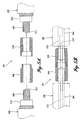
- FIGURE 4A illustrates another embodiment of a joint assembly 401' utilizing bolt-type connector 420' for fastening the bolt-type connector 420' to a pair of conductive core ends 404' and 406'.
- the embodiment of FIGURE 4A comprises a similar construction to the splice 401 depicted in FIGURES 3A-3C, except the bolt-type connector 420' utilizes threaded bolts to attach the bolt-type connector 420' to the conductive core ends 404' and 406'.
- the bolt-type connector 420' comprises at least one threaded aperture on the sides of the connector 420', where each aperture is sized and positioned to receive a threaded bolt 422.
- the threaded bolts 422 are configured and positioned to compress onto the conductive core ends 404' and 406' when tightened thereby holding the core ends 404' and 406' in place.
- FIGURES 4B and 4C illustrate other embodiments of joint assemblies 401" and 401"' utilizing different tube configurations.
- the joint assembly 401" of FIGURE 4B comprises a similar construction as the joint assembly 401 of FIGURE 4A, except the joint assembly 401" of FIGURE 4B only comprises one collar 409.
- the joint assembly 401''' of FIGURE 4C comprises a similar construction as the joint assembly 401 of FIGURE 4A, except the joint assembly 401" of FIGURE 4C utilizes two tubes 489 and 490 with hose barb ends and a flexible tube 488.
- the method involves the construction of the joint assembly 401 depicted in FIGURES 3A-3C.
- the joint assembly 401 is used to attach two flow-through cables 400 and 402, each having at least one conduit 412 and 414 in the conductive core 404 and 406.
- the method involves inserting a tube 410 into the conduit 412 of the first cable 400.
- the tube 410 should be inserted into the conduit such that passes through the conduit beyond the area where the insulation 416 is stripped from the conductive core 404. At this point, the tube 410 may be secured to the conduit 412.
- a collar 409 may be compressed on the conduit 412 to fasten the tube 410 in place.
- the tube 410 can also be secured to the conduit 412 by other mechanisms such as a hose barb tube or conventional seals or adhesives.
- a connector 420 is positioned over the conductive core 404 and secured into place. As described above, the connector 420 can be secured onto the conductive core 404 by a crimping method.
- the tube 410 should be long enough to protrude beyond the connector 420 after the tube 410 and connector 420 are both positioned onto the conductive core 404. This way, when the second cable 402 is aligned with the first cable 400, the tube 410 can be inserted into the conduit 414 before the connector 420 covers the conduit 414.
- the metal tubing 410 should also be long enough to extend through the exposed portion of the conductive core 404 and 406 on each cable 400 and 402. Once the connector 420 and cables 400 and 402 are properly aligned, the conductive core 406 is inserted into the connector 420 and the connector 420 is then compressed onto the conductive core 406 of the second cable 402.
- FIGURES 3A and 3B also illustrate the components utilized in another method for constructing a splice assembly.
- the second method also utilizes a single-piece connector 420.
- the insulation 416 of the first cable 400 is stripped back to accommodate the full length of the connector 420.
- the connector 420 is slid over the exposed conductive core 404 of the first cable 400.
- the tube 410 is inserted into the first conduit 412.
- a substantial portion of the tube 410 is inserted into the first conduit 412.
- the tube 410 is withdrawn from the first cable 400 as it is inserted into the second cable 402.
- the tube 410 should be adjusted until the middle of the tube 410 is centered between the two cable ends.
- the tube 410 may be secured to the conduits 412 and 414.
- collars 408 and 409 may be used to fasten the tube 410 in place.
- the connector 420 is slid from the first cable 400 toward the second cable 402 until the middle of the connector 420 is centered between the two cable ends. Once in place, the connector 420 is then secured to anchor the two conductive cores 404 and 406.
- FIGURE 3C illustrates a fully assembled joint 401.
- the tube 410 is inserted into both cable conduits 412 and 414.
- the connector 420 is affixed to the two conductive cores 404 and 406. As illustrated, the tube 410 is long enough to extend through the exposed portions of the conductive cores 404 and 406 and past the insulation 416 and 418 of each cable. This apparatus prevents the conduits 412 and 414 from being crushed when the connector 420 is compressed on the conductive cores 404 and 406.
- FIGURE 4A illustrates another fully assembled joint 401' using a bolt-type connector 420'.
- This splice assembly 401' is assembled in the same manner using the previous methods described above.
- One difference between the embodiment of FIGURE 4A and the previous embodiment of FIGURES 3A-3C is that the connector 420' is secured to the conductors 404' and 406' with bolts 422 instead of mechanical compression.
- the connector 420' is suitably formed from aluminum, copper, or any other conductive material with similar strength properties.
- FIGURE 4B illustrates another configuration of the splice assembly 401.
- the assembly process is similar to that describing the splice assembly 401 in FIGURE 3C, but this process does not include inserting the collar 408.
- the tube 410 is held by the mechanical compression of the connector 420 or by another conventional sealant as described above.
- FIGURE 4C illustrates another configuration of the splice assembly 401'''.
- the embodiment of FIGURE 4C involves the use of two tubes 489 and 490 with hose barb ends and a flexible tube 488 connecting the two tubes 489 and 490.
- the flexible tubing is made from nylon or other like material.
- the process of assembling this splice involves inserting the tubes 489 and 490 into the conduits and then securing them in place.
- the connector 420 is slid over the conduit 404.
- the tube 488 is connected to the two tubes 489 and 490 and held into place by the hose barbs.
- the connector 420 is then slid over the conductive cores 404 and 406 of each cable 400 and 402 and then secured into place using one of the crimping or bolt methods as described above.
- this configuration using the flexible tubing 488 is used in the single piece connector 420, this configuration utilizing the flexible tubing 488 can be used in other splice assemblies, such as the two-part connector as shown in FIGURE 5A.
- the joint assembly 501 shown in FIGURES 5A and 5B utilizes a two-part connector 508 and 510 and a tube 519 that is to be installed in a manner similar to the embodiments described above.
- the total length of the two connector parts is close to the length of the one-piece connector, thereby eliminating the need for an elongated splice as required by the above-described method.
- the first half of the two-part connector 508 is slid over the prepared end of the first cable 500 and the other half 510 is slid over the end of the second cable 502.
- a tube 519 is inserted into the first conduit 512. After the cable ends are aligned, the tube 519 is withdrawn from the first conduit 512 as it is inserted into the second conduit 514. The tube 519 is moved until the middle of the tube 519 is centered between to two cable ends.
- the two connector halves 508 and 510 are then joined and the entire connector is secured to the conductive cores 506 and 504.
- the two connector halves 508 and 510 may be crimped together to preclude their separation.
- the two connector halves may also be secured by the use of other techniques such as an adhesive, welding, or a threaded connection.
- the present invention is not limited to threaded connections, as there are many ways to join the two halves of the connector including an interference fit or a twist-lock fit. Even a low tolerance fit can be made permanent and provide the required electrical and thermal connection by the application of a crimp over the male and female portion of the connector halves.
- the other end of the cable 400 may be connected to another splice assembly in the same manner as described above.
- another tube (not shown) is connected to the other cable end, and another collar and connector is applied to secure the tube and cable.
- these splice procedures can be used with a cable having a center strand conduit design.
- the procedures also apply to cables having outer strand conduits, middle strand conduits, and multi-layer strand conduits.
- These different types of cables can all be connected inside a splice connector using sealed tubes.
- the connector either in the one-piece or two-piece design, can then be crimped or mechanically bonded, and a splice covering can be applied in the conventional way.
- conduits from both cable ends can be connected in various ways. These connection procedures are similar to the other embodiments described above, involving commercially available couplings and fittings. As illustrated in FIGURE 6, these conduits 604 would be joined outside of the insulating splice body 606 in a manner analogous to the way neutral wires are trained around the splice. The entire assembly could optionally be covered with a re-jacketing sleeve (not shown).
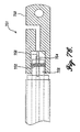
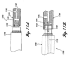
- FIGURES 7A and 7B another embodiment of joint assembly 750 will now be described in greater detail.
- the embodiment of FIGURES 7A and 7B is designed for cables that have conduits in the conductor shield or between the electrically conductive strands.
- the embodiment of FIGURES 7A and 7B comprises the structure of the joint assembly 401 of FIGURE 3A, where a hollowed cylindrical shaped connector is used to provide sealed fluidic communication between two cable ends.
- the embodiment of FIGURES 7A and 7B comprises a connector 702 with an elastomeric insert 704 to create a seal between the cable and the connector 702.
- the elastomeric insert 704 will form a seal between the surface of the conductor 708 and the surface of the connector's cylindrical cavity when the connector is secured in place. This allows the fluid in the conduit 710 to flow into the connector 702 without fluid leaking outside of the seal.
- FIGURE 7B illustrates a cable connector using two elastomeric inserts 704 and 705, two sections of tubing 712 and 714, and a hollow case connector 702.
- This casing can use a crimp method or other conventional splice methods may be applied to affix the two cables 700 and 701.
- This design allows the two cable conduits 710 and 711 to exchange a gas or fluid without exposing the insulating splice to fluid contact or pressure.
- a conventional splice, as shown as item 606 in FIGURE 6, may then be applied over the connector 702.
- FIGURES 7A and 7B only depict a cable having only one center conduit, this invention also applies to cables having a plurality of conduits in or near the conductive core.
- FIGURE 7C is an illustration of a terminator using an elastomeric insert 752.
- the conduit, conductor, and cylindrical opening of the terminator are all attached using the method as described above with reference to FIGURES 7A-7B. Additional information regarding the terminator is discussed in more detail below.
- the present invention also provides several devices and methods for terminating flow-through cables. More specifically, the present invention includes several embodiments for terminating cables while providing external access to the fluidic conduits in the cables.
- the various embodiments of the present invention provide terminators for live-front devices, terminators with a conductive exposed surface, and dead-front devices, terminators with a non-conductive exposed surface.
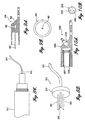
- a flow-through cable 800 can be anchored to a terminator 804 while allowing external access to the cable conduit 801.
- the terminator assembly 899 includes a flow-through cable 800 with a conduit 801, a semi-flexible tube 802 connected to another tube 803, and a terminator 804.
- the terminator assembly 899 is also configured to provide electronic communication between the cable conductor 822 and the terminator 804.
- the one embodiment of the present invention involves the utilization of a semi-flexible tube 802 that is not mechanically bonded or sealed to the termination connector 804. If there is only one conduit 801 in the cable 800, a single tube 803 is inserted into the conduit 801 and routed through a cavity 811 in the terminator 804. The tube 803 can be directly inserted in the conduit 801 and bonded to the conduit 801 with an adhesive. Alternatively, a plug assembly 808 can be used to attach the semi-flexible tube 802 to the conduit 801.
- FIGURE 8A depicts an embodiment using a plug assembly 808 where the semi-flexible tube 802 is connected to a rigid or semi-rigid tubing 803. Much like the assembly depicted in FIGURE 4C, the semi-flexible tubing 802 is connected to the rigid or semi-rigid tubing 803 by a mechanical connector or other conventional tube connecting devices.
- FIGURE 8A Another embodiment shown in FIGURE 8A involves the utilization of unbonded tubes for a flow-through cable 815 having a plurality of conduits 807.
- the plug assembly 810 of this embodiment provides gas and fluid communication between the cable conduits 807 and the semi-flexible tube 812.
- the plug assembly 810 comprises a hollowed casing 815 that has apertures on one side allowing fluidic communication between a plurality of tubes 805 and the internal section of the hollowed casing 815.
- a semi-flexible tube 812 is also attached to the plug assembly 810; where the flexible tube 812 is attached to allow fluidic communication between the flexible tube 812 and the internal section of the hollowed casing 815.
- the tubes 805 are suitably received by the cable conduit 807 to allow fluidic communication between the cable conduit 807 and the semi-flexible tube 812.
- FIGURE 8D illustrates a perspective view of the plug assembly 810. Although this particular embodiment shows a three-tube configuration, this invention relates to configurations with any number of tubes 805.
- the tube 812 is then passed through a cavity 811 in the connector 804.
- the tube 812 is exposed on the outside of the connector 804 to provide injection access to the conduit 807 from the tube 812 without requiring a user to remove the cable 815 from the terminator 804 to apply fluid to the cable conduits.
- FIGURE 9A is a side view of the single-tube cable terminator assembly 900 and FIGURE 9B is an end view of the single-tube cable terminator assembly 900.
- the tube 902 made of a rigid or semi-rigid material, is bonded to the terminator 908.
- the terminator 908 is made from a conductive material used in common terminators.
- the tube 902 should be long enough to extend through the full length of the terminator's cylindrical opening.
- a long tube 902 that extends past the end of the connector casing 908 facilitates easy cable installation.
- the tube 902 passes into the cable's conduit before the cable end enters the terminator cylindrical opening.
- the tube 902 is fixed to the casing 908 and configured to only allow fluidic communication between the inner portion of the tube 902 and the port 906.
- a cable conductor is inserted into the terminator 900 and the tube 902 is inserted into the cable conduit.
- the terminator 900 is also configured to provide electronic communication between the casing 908 and the cable conductor. Once a cable is fixed in the terminator 900, injection access to the cable conduit is allowed through a port 906.
- the port 906 can be accessed using several commonly known tube connecting techniques, some non-limiting examples include: threaded connectors, injection fittings, valves, or plugs could be fitted to this port.
- FIGURES 10A and 10B depict another embodiment of a terminator that involves bonded micro-tubes 1002.
- the bonded multi-tube terminator 1000 allows injection access to cable conduits (not shown) through a hollowed casing 1008 having a plurality of tubes 1002 with gas and fluid communications to an access port 1010. This configuration is made for cables having multiple conduits in the intermediate or outer layers of the conductor.
- FIGURE 10A is a side view of the multi-tube cable terminator 1000 and FIGURE 10B is an end view of the multi-tube cable terminator 1000.
- the tubes 1002 are bonded to the terminator casing 1008.
- the micro-tubes 1002 are also made of a rigid or semi-rigid material.
- the tubes 1002 are also arranged around the cylindrical opening so they are align with the conduits in a flow-through cable. When the cable is inserted into the terminator opening, the micro-tubes 1002 slide into the conduits in the cable.
- access to the flow-path can be through a threaded opening intersecting the cavity where the bonded microtubes 1002 terminate. This will allow direct connection of injection equipment used to apply fluid to the cable conduit.
- the access port 1010 can be plugged or attached to an external tube (not shown) similar to the techniques described for the access port 906 in FIGURE 9A.
- the present invention provides another configuration for terminating a flow-through cable using a circumferential seal 1102 around the conductor strands 1101.
- an elastomeric sealing material 1102 is placed inside the termination connector 1104. Once the cable 1100 is inserted into the connector 1104, the connector 1104 is secured down on the cable to secure the connection. The crimping force applied over the elastomeric material 1102 seals the strands of the cable.
- This design allows a fluidic communication between conduits in the cable (not shown) and the valves in the terminator 1104.
- the valves and openings in the terminator 1104 can be sealed by various devices as shown in the previous embodiments.
- This particular non-limiting example illustrates an optional injection access 1106 that can be used in addition to the other injection access 1108. This optional injection access can also be used in other terminators and cable joining apparatuses shown in previous embodiments.
- this embodiment utilizing a circumferential seal 1102, which mainly works for strand-filled cables.
- the termination connector 1104 has a channel leading from the strands to a port that can be connected to injection equipment or may pass through the connector to another cable.
- FIGURE 11B illustrates an embodiment of FIGURE 11A where a compression resistant tube 1109 is inserted in the conduit 1110 prior to the installation of the connector 1104 to prevent the conduit 1110 from collapsing. This example is similar to the terminator apparatus 751 shown in FIGURE 7C.
- the present invention includes two alternative embodiments that allow the above-described embodiments to be applied to dead-front terminations.
- the above-described terminators shown in FIGURES 9A-10B are fitted with several components to allow fluidic access to shielded terminators.
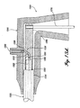
- FIGURE 12 is a sectional view of a cable 1295 connected to a dead-front terminator 1398 with a tube 1291 bonded to the terminator housing 1206.
- This configuration is similar to the terminator configuration shown in FIGURE 9A, except this embodiment further comprises a nonconductive protective housing 1200.
- a tube 1291 is inserted into the cable conduit and the tube 1291 is connected to the conductive terminator 1206 such that it is sufficiently fixed into place.
- the tube 1291 is inserted into the conduit 1292 and configured to allow fluidic communication between the terminator access port 1290 and the conduit 1292. Injection access can be made through the terminator access port 1290 by the use of an injection tube 1289.
- the injection tube 1289 can be fixed to the terminator access port 1290 with a thread locking device or other like devices.
- the terminator access port 1290 must be aligned with the elbow access port 1202 to allow for a proper fitting of the injection tube 1289.
- the terminator access port 1290 can also be sealed by the use of a threaded plug (not shown).
- the embodiment of FIGURE 12 provides electronic communication between the cable conductor 1293 and the terminating body 1376 via the terminator casing 1206.
- the present invention provides a dead-front termination utilizing a tube to provide a contiguous flow path out of a dead-front termination.
- This embodiment allows a person to access the fluid conduits of a cable terminated by a dead-front termination via an extended flexible tubing, as shown in FIGURE 13A.
- the construction of the terminator shown in FIGURE 13A is similar to the construction of the terminator depicted in FIGURES 8A and 8B, where the tube can be made of any flexible, dielectric material sufficient to allow fluidic communication at high pressures.
- FIGURE 13A is a sectional view of a cable connected to a dead-front terminator configuration with a flexible tube 1312 that is not bonded to the terminator housing 1206.
- the flexible tube 1312 is connected to a port insert 1300 which is configured to allow for fluidic communication between the port insert 1300 and the cable conduit 1392.
- the flexible tube 1312 is bonded to the cable conduit 1392 in a manner similar to the embodiment of FIGURES 8A and 8B.
- the port insert 1300 is bonded to the flexible tubing material 1391 and the tubing material 1391 is connected to a tube 1389 inserted in the conduit 1392.
- This configuration allows fluid and gas injection into the cable conduit through port nonconductive protective housing 1200.
- An external tubing (not shown) can be connected to the port opening 1202 by the use of a standard thread locking device or other like mechanisms.
- a threaded plug (not shown) may be inserted into the access port 1202.
- FIGURE 13C illustrates how a tube 1312 can be connected to an elbow port insert 1300.
- a variety of mechanical bonds are possible to attach the tube 1312 to the elbow port, including: a solvent weld, an adhesive bond, an interference fit, an o-ring-like seal, or a thermal weld.
- the tube 1312 is first routed through the port 1390, cut to a predetermined length, and bonded to the port insert 1300 at the tip 1302.
- the port insert 1300 is bonded and sealed to the tube 1312, the port insert 1300 is inserted into an injection elbow access port 1202 where it snaps into place with a permanent interference fit or other bonding techniques as illustrated above.
- the elbow access port 1310 is also depicted as the access port 1202 in FIGURE 12.
- a conventional injection cap or plug, or a permanent cap or plug, already known in the art is inserted into the inner cavity of the port insert to allow fluid injection.
- the routed access port alternative is compatible with all termination embodiments described above.
- outside flow conduits are used exclusively for the injection, the conduits should be severed outside of the crimp or mechanical connector to facilitate flow as illustrated by FIGURE 14.
- the method of cutting these outside tubes shorter than the strands is a novel way to facilitate flow for use with conventional molded, coldshrink, hand-taped, and heat-shrink splices and conventional termination injection adapters.
Landscapes
- Cable Accessories (AREA)
- Coupling Device And Connection With Printed Circuit (AREA)
- Communication Cables (AREA)
- Quick-Acting Or Multi-Walled Pipe Joints (AREA)
- Processing Of Terminals (AREA)
- Media Introduction/Drainage Providing Device (AREA)
Claims (37)
- Verfahren zum Verbinden eines ersten Durchflusskabels (400) und eines zweiten Durchflusskabels (402), bei dem das erste und das zweite Durchflusskabel eine Rohrleitung (412), einen elektrisch leitenden Kernleiter (404) und eine Isolierung (416) umfassen, wobei das Verfahren dadurch gekennzeichnet wird, dass es folgendes umfasst:(a) Einführen eines Rohrstücks (410) in die Rohrleitung des ersten Durchflusskabels;(b) Anordnen eines Steckverbinders (420) über wenigstens einen Abschnitt des ersten Durchflusskabels;(c) Befestigen des Steckverbinders an dem ersten Durchflusskabel;(d) Einführen des Rohrstücks (410) in die Rohrleitung des zweiten Durchflusskabels; und(e) Befestigen des Steckverbinders (420) an dem zweiten Durchflusskabel.
- Verfahren gemäß Anspruch 1, wobei die Einführschritte (a) und (d) das Einführen des Rohrstücks in die Rohrleitung bis zu einer vorbestimmten Tiefe umfassen, wobei die vorbestimmte Tiefe sich über einen abgeschälten Abschnitt der Isolierung hinaus erstreckt.
- Verfahren gemäß Anspruch 1, ferner umfassend:Befestigen des Rohrstücks an der Rohrleitung des ersten Durchflusskabels; undBefestigen des Rohrstücks an der Rohrleitung des zweiten Durchflusskabels.
- Verfahren gemäß Anspruch 1, ferner umfassend:Entfernen der Isolierung von dem ersten Durchflusskabel; undEntfernen der Isolierung von dem zweiten Durchflusskabel.
- Verfahren gemäß Anspruch 1, wobei das erste und das zweite Durchflusskabel ferner eine Isolierungsabschirmung (32), eine Umhüllung (22) und mehrere Rohrleitungen (412) aufweisen, ferner umfassend:Verbinden der mehreren Rohrleitungen des ersten Durchflusskabels mit den mehreren Rohrleitungen des zweiten Durchflusskabels.
- Verfahren gemäß Anspruch 5, wobei die mehreren Rohrleitungen in der Umhüllung angeordnet sind.
- Verfahren gemäß Anspruch 1, wobei das Rohrstück aus Stahl besteht.
- Verfahren gemäß Anspruch 1, wobei das Anordnen des Steckverbinders über wenigstens einem Abschnitt des ersten Durchflusskabels das Anordnen des Steckverbinders über den elektrisch leitenden Kernleiter des ersten Durchflusskabels umfasst und wobei das Verfahren ferner umfasst:Herausziehen des Rohrstücks aus der Rohrleitung des ersten Durchflusskabels bis in die Rohrleitung des zweiten Durchflusskabels;Verschieben des Steckverbinders von dem elektrisch leitenden Kernleiter des ersten Durchflusskabels über den elektrisch leitenden Kernleiter des zweiten Durchflusskabels derart, dass der Steckverbinder einen Abschnitt der elektrisch leitenden Kernleiter des ersten und des zweiten Durchflusskabels abdeckt; undVercrimpen des Steckverbinders mit den elektrisch leitenden Kernleitern des ersten und des zweiten Durchflusskabels.
- Verfahren gemäß Anspruch 8, wobei der Schritt des Verschiebens ferner das Verschieben des Crimpsteckverbinders derart, dass das Zentrum des Crimpsteckverbinders im wesentlichen zwischen dem ersten und dem zweiten freigelegten elektrisch leitenden Kernleiter ausgerichtet ist, umfasst.
- Verfahren gemäß Anspruch 8, wobei das Verfahren ferner
das Entfernen der Isolierung von dem ersten Durchflusskabel umfasst, wodurch der elektrisch leitende Kernleiter des ersten Durchflusskabels freigelegt wird, und wobei das Abschälen des ersten Durchflusskabels ferner das Entfernen der Isolierung über eine Länge, die gleich oder länger als die Länge des Steckverbinders ist, umfasst. - Verfahren gemäß Anspruch 8, wobei das erste und das zweite Durchflusskabel ferner eine Isolierungsabschirmung (32), eine Ummantelung (22) und mehrere Rohrleitungen aufweisen, ferner umfassend:Verbinden der mehreren Rohrleitungen des ersten Durchflusskabels mit den mehreren Rohrleitungen des zweiten Durchflusskabels.
- Verfahren gemäß Anspruch 11, wobei die mehreren Rohrleitungen in der Ummantelung angeordnet sind.
- Verfahren gemäß Anspruch 8, wobei das Rohrstück aus Stahl besteht.
- Ein Verfahren zum Verbinden eines ersten Durchflusskabels (500) und eines zweiten Durchflusskabels (502), das einen zweiteiligen Crimpsteckverbinder (501) nutzt, wobei der zweiteilige Crimpsteckverbinder ein erstes Crimpteil (308) und ein zweites Crimpteil (510) umfasst, und wobei das erste und das zweite Durchflusskabel eine Rohrleitung (512), einen elektrisch leitenden Kernleiter (506) und eine Isolierung (516) umfassen, dadurch gekennzeichnet wird, dass es folgendes umfasst:(a) Anordnen des ersten Crimpteils auf dem elektrisch leitenden Kernleiter des ersten Durchflusskabels,(b) Anordnen des zweiten Crimpteils auf dem elektrisch leitenden Kernleiter des zweiten Durchflusskabels,(c) Einführen eines Rohrstücks in die Rohrleitung des ersten Durchflusskabels,(d) Herausziehen des Rohrstücks aus der Rohrleitung des ersten Durchflusskabels bis in die Rohrleitung des zweiten Durchflusskabels,(e) Verbinden des ersten Crimpteils mit dem zweiten Crimpteil, wodurch eine Crimpverbindung erzeugt wird; und(f) Vercrimpen des ersten und des zweiten Crimpteils mit dem elektrisch leitenden Kernleiter des ersten und dem des zweiten Durchflusskabels.
- Verfahren gemäß Anspruch 14, ferner umfassend Crimpen der Crimpverbindung.
- Verfahren gemäß Anspruch 14, wobei das erste und das zweite Crimpteil eine mit Gewinde versehene Nut umfassen, wobei diese eine gesicherte Verbindung zwischen dem ersten und dem zweiten Crimpteil erzeugt.
- Verfahren gemäß Anspruch 14, ferner umfassend:Entfernen der Isolierung von dem ersten Durchflusskabel; undEntfernen der Isolierung von dem zweiten Durchflusskabel.
- Verfahren gemäß Anspruch 14, wobei der Schritt des Herausziehens (d) das Herausziehen des Rohrstücks aus der Rohrleitung des ersten Durchflusskabels so weit, dass das Zentrum des Rohrstücks im wesentlichen mittig zwischen dem ersten und dem zweiten Durchflusskabel angeordnet ist, umfasst.
- Verfahren gemäß Anspruch 14, wobei das erste und das zweite Durchflusskabel ferner eine Isolierungsabschirmung (32), eine Ummantelung (22) und mehrere Rohrleitungen aufweisen, ferner umfassend:Verbinden der mehreren Rohrleitungen des ersten Durchflusskabels mit den mehreren Rohrleitungen des zweiten Durchflusskabels.
- Verfahren gemäß Anspruch 19, wobei die mehreren Rohrleitungen in der Ummantelung angeordnet sind.
- Verfahren gemäß Anspruch 14, wobei das Rohrstück aus Stahl besteht.
- Kabelverbindung für ein Durchflusskabel, wobei das Durchflusskabel eine Rohrleitung (710), einen elektrisch leitenden Kernleiter (708) und eine Isolierung (706), die die Rohrleitung und den elektrisch leitenden Kernleiter umgibt, umfasst, dadurch gekennzeichnet, dass sie
ein Rohrstück (712) umfasst, wobei das Rohrstück mit der Rohrleitung verbunden ist, das eine Fluidleitverbindung zwischen dem Rohrstück und der Rohrleitung ermöglicht; und
ein leitendes Gehäuse (702), das einen ersten Hohlraum und einen zweiten Hohlraum aufweist, wobei der zweite Hohlraum zur Aufnahme eines Endabschnitts des elektrisch leitenden Kernleiters ausgebildet ist und wobei der erste Hohlraum sich von einer Innenfläche des zweiten Hohlraums zu der Außenfläche des leitenden Gehäuses erstreckt und wobei der erste und der zweite Hohlraum so miteinander verbunden sind, dass eine Fluidleitung zwischen der Rohrleitung und dem ersten Hohlraum ermöglicht ist, umfasst. - Kabelverbindung gemäß Anspruch 22, ferner umfassend ein zweites Rohrstück (802), wobei das zweite Rohrstück mit dem Rohrstück (803) zur Bereitstellung einer Fluidleitung zwischen der Rohrleitung und dem zweiten Rohrstück verbunden ist und wobei das zweite Rohrstück sich von dem Rohrstück zur Außenseite des leitenden Gehäuses über den ersten Hohlraum erstreckt.
- Kabelverbindung gemäß Anspruch 22, wobei das Durchflusskabel mehrere Rohrleitungen umfasst und ferner
eine hohle Steckerverbindung umfasst, welche mehrere im wesentlichen starre Rohre und einen Rohrleitungssteckverbinder umfasst, wobei die mehreren im wesentlichen starren Rohre (750) und der Rohrleitungssteckverbinder eine Fluidleitung zwischen den mehreren Rohren und dem Rohrstück vorsehen, wobei die Fluidleitung zwischen den mehreren Rohrleitungen und dem ersten Hohlraum über die hohle Steckerverbindung und das Rohrstück stattfindet. - Kabelverbindung gemäß Anspruch 24, ferner umfassend Verriegelungsmittel zum Festsetzen des elektrisch leitenden Kernleiters an dem leitenden Gehäuse.
- Kabelverbindung gemäß Anspruch 25, wobei die mehreren Rohrleitungssteckverbinder an der hohlen Steckverbindung derart angebracht ist, dass jeder Rohrleitungssteckverbinder der mehreren Rohrleitungssteckverbinder im wesentlichen mit den mehreren Rohrleitungen des Durchflusskabels ausgerichtet ist.
- Kabelverbindung gemäß Anspruch 22, wobei der zweite Hohlraum eine allgemein zylindrische Form aufweist, wobei das Rohrstück an der Basis des zweiten im allgemeinen zylindrischen Hohlraums starr befestigt ist und wobei das Rohrstück im wesentlichen mit der Achse des im allgemeinen zylindrischen Hohlraums ausgerichtet ist, und wobei das Rohrstück mit dem ersten Hohlraum verbunden ist, um eine Fluidleitung zwischen der Rohrleitung und dem ersten Hohlraum zu ermöglichen.
- Kabelverbindung gemäß Anspruch 27, wobei die Länge des Rohrstücks länger als die Länge des zweiten im allgemeinen zylindrischen Hohlraum ist.
- Kabelverbindung gemäß Anspruch 28, wobei das Rohrstück aus einem starren Metallwerkstoff besteht.
- Kabelverbindung gemäß Anspruch 27, wobei das leitende Gehäuse ferner mehrere Rohre umfasst, die an der Basis des zweiten im allgemeinen zylindrischen Hohlraums starr befestigt sind, und wobei die mehreren Rohre im wesentlichen zu der Achse des im allgemeinen zylindrischen Hohlraums ausgerichtet sind, und wobei die mehreren Rohre an der Basis des ersten Hohlraums befestigt sind, um eine Fluidleitung zwischen den mehreren Rohren und dem ersten Hohlraum zu ermöglichen.
- Kabelverbindung gemäß Anspruch 30, wobei die mehreren Rohre aus einem starren Metallwerkstoff hergestellt sind.
- Kabelverbindung gemäß Anspruch 30, wobei die Länge der mehreren Rohre länger als die Länge des zweiten im allgemeinen zylindrischen Hohlraums ist.
- Kabelverbindung gemäß Anspruch 30, wobei der erste Hohlraum eine zylindrische Form mit einer Gewindefläche aufweist, die zur Innenseite des Hohlraums weist.
- Kabelverbindung gemäß Anspruch 22, wobei der zweite Hohlraum eine im allgemeinen zylindrische Form aufweist und wobei der zweite im allgemeinen zylindrische Hohlraum mit dem ersten Hohlraum verbunden ist und eine Verbindung zwischen dem elektrisch leitenden Kernleiter und dem Rohrstück erlaubt.
- Kabelverbindung gemäß Anspruch 22, ferner umfassend ein zweites Rohrstück (803), wobei das zweite Rohrstück (803) mit dem Rohrstück verbunden ist und eine Fluidleitung zwischen der Rohrleitung und dem zweiten Rohrstück bereitstellt.
- Kabelverbindung gemäß Anspruch 22, wobei das Rohrstück in die Rohrleitung des ersten Durchflusskabels und eines zweiten Durchflusskabels eingeführt ist und wobei der Crimpsteckverbinder um den leitenden Kernleiter des ersten Durchflusskabels und dem des zweiten Durchflusskabels angeordnet ist, und wobei der Steckverbinder zur Verbindung des ersten Durchflusskabels mit dem zweiten Durchflusskabel derart ausgebildet ist, dass die Kabelverbindung eine Fluidleitung und elektronische Verbindung zwischen dem ersten Durchflusskabel und dem zweiten Durchflusskabel bereitstellt.
- Kabelverbindung (1103) für ein Durchflusskabel, das einen elektrisch leitenden Kernleiter (1101), der derart aufgebaut ist, dass eine Fluidleitung durch diesen möglich ist, und eine Isolierung, die den elektrisch leitenden Kernleiter umgibt, und wenigstens eine Rohrleitung aufweist, die vorgesehen ist, um eine Fluiddurchleitung zu ermöglichen,
dadurch gekennzeichnet,
dass sie ein leitendes Gehäuse (1104), das einen ersten Hohlraum und einen zweiten Hohlraum aufweist, wobei sich der erste Hohlraum von dem zweiten Hohlraum zu wenigstens einer Außenfläche des leitenden Gehäuses erstreckt und wobei der zweite Hohlraum größenmäßig derart ausgebildet ist, dass er einen Endabschnitt des elektrisch leitenden Kernleiters aufnehmen kann, wobei das leitende Gehäuse derart aufgebaut ist, dass eine Fluidleitung zwischen dem ersten und dem zweiten Hohlraum ermöglicht ist, und wobei das leitende Gehäuse derart aufgebaut ist, dass eine Fluidleitung zwischen dem elektrisch leitenden Kernleiter und dem ersten Hohlraum ermöglicht ist.
Applications Claiming Priority (3)
| Application Number | Priority Date | Filing Date | Title |
|---|---|---|---|
| US15527999P | 1999-10-11 | 1999-10-11 | |
| US155279P | 1999-10-11 | ||
| PCT/US2000/028104 WO2001028059A1 (en) | 1999-10-11 | 2000-10-11 | Connections and terminations for cables |
Publications (2)
| Publication Number | Publication Date |
|---|---|
| EP1222723A1 EP1222723A1 (de) | 2002-07-17 |
| EP1222723B1 true EP1222723B1 (de) | 2007-03-07 |
Family
ID=22554776
Family Applications (1)
| Application Number | Title | Priority Date | Filing Date |
|---|---|---|---|
| EP00973461A Expired - Lifetime EP1222723B1 (de) | 1999-10-11 | 2000-10-11 | Kabelverbindungen sowie kabelendverschlüsse |
Country Status (8)
| Country | Link |
|---|---|
| US (1) | US6489554B1 (de) |
| EP (1) | EP1222723B1 (de) |
| AT (1) | ATE356457T1 (de) |
| AU (1) | AU1196501A (de) |
| CA (1) | CA2386210C (de) |
| DE (1) | DE60033832T2 (de) |
| TW (1) | TW546875B (de) |
| WO (1) | WO2001028059A1 (de) |
Families Citing this family (29)
| Publication number | Priority date | Publication date | Assignee | Title |
|---|---|---|---|---|
| DE10242198C5 (de) * | 2002-09-10 | 2011-06-30 | Zwei plus zwei GmbH, 50933 | Körperaufnahme für ein fahrbares Rahmengestell |
| US6517366B2 (en) * | 2000-12-06 | 2003-02-11 | Utilx Corporation | Method and apparatus for blocking pathways between a power cable and the environment |
| EP1351168A4 (de) * | 2000-12-12 | 2005-03-30 | Chuo Hatsujo Kk | Verfahren und vorrichtung zur berechnung der verdrahtungsroute eines steuerkabels |
| US6852922B2 (en) * | 2001-07-13 | 2005-02-08 | Houston Wire & Cable Company | Apparatus and method for sealing a conduit |
| US6982384B2 (en) * | 2003-09-25 | 2006-01-03 | Intelliserv, Inc. | Load-resistant coaxial transmission line |
| CA2557169C (en) * | 2004-03-01 | 2014-07-15 | Novinium, Inc. | High-pressure power cable connector |
| US7331806B2 (en) | 2004-08-25 | 2008-02-19 | Utilx Corporation | Cable connectors with internal fluid reservoirs |
| US7704087B1 (en) | 2004-09-03 | 2010-04-27 | Utilx Corporation | Check valve for charge tank |
| US7377825B2 (en) * | 2004-09-21 | 2008-05-27 | Illinois Tool Works Inc. | High-power electrical quick connector |
| US7124724B2 (en) * | 2005-02-15 | 2006-10-24 | Champion Aerospace, Inc. | Air-cooled ignition lead |
| US7256350B2 (en) | 2005-04-19 | 2007-08-14 | Utilx Corporation | Fluid reservoir for a cable span |
| US20060231283A1 (en) | 2005-04-19 | 2006-10-19 | Stagi William R | Cable connector having fluid reservoir |
| US7538274B2 (en) * | 2006-01-23 | 2009-05-26 | Novinium, Inc. | Swagable high-pressure cable connectors having improved sealing means |
| WO2008088618A1 (en) * | 2007-01-12 | 2008-07-24 | Utilx Corporation | Composition and method for restoring an electrical cable and inhibiting corrosion in the aluminum conductor core |
| DE202009008200U1 (de) * | 2009-03-04 | 2010-07-22 | "Zwei Plus Zwei" Marketing Gmbh | Sicherheitseinrichtung |
| CN102687356B (zh) | 2009-09-14 | 2015-11-25 | 罗杰.福克纳 | 地下模块化高压直流电力传输系统 |
| US8475194B2 (en) * | 2009-10-16 | 2013-07-02 | Novinium, Inc. | Reticulated flash prevention plug |
| JP2011097692A (ja) * | 2009-10-28 | 2011-05-12 | Yazaki Corp | ワイヤハーネス |
| US9673606B2 (en) * | 2012-06-15 | 2017-06-06 | Flex-Cable | Pressurized electromechanical cable |
| TWI506901B (zh) * | 2012-07-30 | 2015-11-01 | Hon Hai Prec Ind Co Ltd | 線纜連接方法及線纜連接結構 |
| US10962253B2 (en) | 2015-06-05 | 2021-03-30 | Novinium, Inc. | Systems for circulating air inside a manhole vault |
| US11060754B2 (en) | 2015-06-05 | 2021-07-13 | Novinium, Inc. | Ventilation system for manhole vault |
| WO2017173402A2 (en) | 2016-03-31 | 2017-10-05 | Novinium, Inc. | Smart system for manhole event suppression system |
| US10230222B2 (en) | 2016-04-28 | 2019-03-12 | Novinium, Inc. | Injection electrical connector |
| CN109979658B (zh) * | 2019-03-23 | 2024-06-18 | 江苏华能电缆股份有限公司 | 智能传感宽频承荷探测电缆 |
| RU2745441C1 (ru) * | 2020-07-31 | 2021-03-25 | Акционерное общество "Гипрогазцентр" | Кабель с функцией микроканализации |
| GB2604455B (en) * | 2021-03-05 | 2023-03-01 | Onesubsea Ip Uk Ltd | Cable preperation and injection systems and methods |
| US20250104888A1 (en) * | 2022-01-25 | 2025-03-27 | Kenneth KEGEL | Audio cable with dielectric fluid |
| CN116191142A (zh) * | 2023-01-16 | 2023-05-30 | 江苏中天科技电缆附件有限公司 | 线缆接头 |
Family Cites Families (24)
| Publication number | Priority date | Publication date | Assignee | Title |
|---|---|---|---|---|
| US1846361A (en) | 1928-12-11 | 1932-02-23 | Ernest F Saylor | High voltage plural cable conductor |
| DE582168C (de) * | 1930-09-03 | 1933-08-09 | Siemens Schuckertwerke Akt Ges | Verfahren zur Herstellung von Verbindungsstellen oelgefuellter Kabel |
| US2248588A (en) * | 1940-06-06 | 1941-07-08 | Gen Electric | Gas filled cable installation |
| US2908741A (en) | 1955-11-22 | 1959-10-13 | Thomas F Peterson | Electric cable with pressure compensating means |
| DE1059527B (de) * | 1957-08-05 | 1959-06-18 | Siemens Ag | Kabelmuffe aus einem aushaertenden Giessharz fuer unter Gasinnendruck stehende mehradrige Fernmeldekabel mit kunststoffisolierten Adern und mit einem insbesondere aus Kunststoff bestehenden Kabelmantel |
| US3127467A (en) | 1962-04-13 | 1964-03-31 | William A Toto | Welding cable assembly |
| CH389716A (it) | 1963-04-10 | 1965-03-31 | Pirelli | Procedimento per l'esecuzione di una giunzione su di un cavo ad olio fluido a più conduttori, dispositivo per l'attuazione dello stesso e giunto ottenuto con questo procedimento |
| US3449507A (en) | 1966-12-05 | 1969-06-10 | William H Channell | Cable splice enclosure |
| US3649952A (en) * | 1970-03-18 | 1972-03-14 | Chance Co Ab | Gas-separable electrical connector and method |
| US3732352A (en) | 1971-09-02 | 1973-05-08 | Gen Cable Corp | Construction for end of cable sheath and method of welding sheath |
| US3883208A (en) * | 1973-10-25 | 1975-05-13 | Rte Corp | Visible break tee-connector |
| US3961127A (en) | 1975-06-11 | 1976-06-01 | G & W Electric Specialty Company | Universal power cable joint for use with power cables having various insulations |
| US4202591A (en) * | 1978-10-10 | 1980-05-13 | Amerace Corporation | Apparatus for the remote grounding, connection and disconnection of high voltage electrical circuits |
| US4330681A (en) | 1980-08-18 | 1982-05-18 | Bicc Limited | Fluid-filled electric cable joints and terminations with filtering means |
| US4545133A (en) | 1984-04-20 | 1985-10-08 | American Public Power Association | Apparatus and method for prolonging the service life of electrical power cables |
| IT1177429B (it) | 1984-12-17 | 1987-08-26 | Pirelli Cavi Spa | Giunto tra cavo ad isolante estruso e cavo con isolante assistito da un dielettrico fluido |
| US4888886A (en) * | 1987-09-24 | 1989-12-26 | Empire State Electric Energy Research Corporation | Apparatus for use in impregnating electrical cables |
| US4902092A (en) * | 1988-01-04 | 1990-02-20 | Prestolite Wire Corporation | Multi-piece connector and receptacle therefor |
| US4946393A (en) * | 1989-08-04 | 1990-08-07 | Amerace Corporation | Separable connector access port and fittings |
| US5004865A (en) | 1989-10-10 | 1991-04-02 | Krupnicki Theodore A | Splicing device for fluid-cooled electric cables |
| US5215475A (en) * | 1992-07-02 | 1993-06-01 | Amerace Corporation | Devices for use with high voltage system components for the safe expulsion of conductive moisture within such components |
| US5612508A (en) * | 1995-03-06 | 1997-03-18 | Watteredge-Uniflex, Inc. | Flexible jumper and method of making |
| US5621841A (en) * | 1995-09-20 | 1997-04-15 | Siecor Corporation | Optical fiber cable containing ribbons in stranded tubes |
| US5907128A (en) | 1997-02-13 | 1999-05-25 | Utilx Corporation | Cable connector with fluid injection port |
-
2000
- 2000-10-11 DE DE60033832T patent/DE60033832T2/de not_active Expired - Fee Related
- 2000-10-11 WO PCT/US2000/028104 patent/WO2001028059A1/en not_active Ceased
- 2000-10-11 US US09/689,296 patent/US6489554B1/en not_active Expired - Lifetime
- 2000-10-11 AT AT00973461T patent/ATE356457T1/de not_active IP Right Cessation
- 2000-10-11 AU AU11965/01A patent/AU1196501A/en not_active Abandoned
- 2000-10-11 CA CA002386210A patent/CA2386210C/en not_active Expired - Fee Related
- 2000-10-11 EP EP00973461A patent/EP1222723B1/de not_active Expired - Lifetime
- 2000-12-08 TW TW089121232A patent/TW546875B/zh not_active IP Right Cessation
Also Published As
| Publication number | Publication date |
|---|---|
| AU1196501A (en) | 2001-04-23 |
| DE60033832T2 (de) | 2007-12-20 |
| DE60033832D1 (de) | 2007-04-19 |
| CA2386210C (en) | 2009-08-11 |
| WO2001028059A1 (en) | 2001-04-19 |
| US6489554B1 (en) | 2002-12-03 |
| EP1222723A1 (de) | 2002-07-17 |
| ATE356457T1 (de) | 2007-03-15 |
| CA2386210A1 (en) | 2001-04-19 |
| TW546875B (en) | 2003-08-11 |
Similar Documents
| Publication | Publication Date | Title |
|---|---|---|
| EP1222723B1 (de) | Kabelverbindungen sowie kabelendverschlüsse | |
| EP1008217B1 (de) | Kabelverbinder mit eingang für injektion eines fluids | |
| US20060169475A1 (en) | Cable fluid injection sleeve | |
| AU2007201817B9 (en) | Optical cable shield layer connection | |
| US5113101A (en) | Watertight seal for plug-in type pothead | |
| US5797761A (en) | Power connector assembly | |
| EP2238649B1 (de) | Segmentierte dekomprimierungresistente kabelverbindung und installationsverfahren | |
| GB2443224A (en) | Connector having removable conductor | |
| CN101208832A (zh) | 具有流体储存器的电缆连接器 | |
| US4073559A (en) | Electrical connector for submersible oil well pump cables | |
| KR100521612B1 (ko) | 케이블 유체 분사 슬리브 | |
| US11721957B2 (en) | Electric submersible pump cable tubing encapsulated cable splice | |
| EP0227658A1 (de) | Kabel- und leitungssystem unter gasdruck | |
| WO1998021798A1 (en) | Bonded sealed closure systems and methods |
Legal Events
| Date | Code | Title | Description |
|---|---|---|---|
| PUAI | Public reference made under article 153(3) epc to a published international application that has entered the european phase |
Free format text: ORIGINAL CODE: 0009012 |
|
| 17P | Request for examination filed |
Effective date: 20020503 |
|
| AK | Designated contracting states |
Kind code of ref document: A1 Designated state(s): AT BE CH CY DE DK ES FI FR GB GR IE IT LI LU MC NL PT SE |
|
| AX | Request for extension of the european patent |
Free format text: AL;LT;LV;MK;RO;SI |
|
| 17Q | First examination report despatched |
Effective date: 20030204 |
|
| GRAP | Despatch of communication of intention to grant a patent |
Free format text: ORIGINAL CODE: EPIDOSNIGR1 |
|
| GRAS | Grant fee paid |
Free format text: ORIGINAL CODE: EPIDOSNIGR3 |
|
| GRAA | (expected) grant |
Free format text: ORIGINAL CODE: 0009210 |
|
| AK | Designated contracting states |
Kind code of ref document: B1 Designated state(s): AT BE CH CY DE DK ES FI FR GB GR IE IT LI LU MC NL PT SE |
|
| PG25 | Lapsed in a contracting state [announced via postgrant information from national office to epo] |
Ref country code: BE Free format text: LAPSE BECAUSE OF FAILURE TO SUBMIT A TRANSLATION OF THE DESCRIPTION OR TO PAY THE FEE WITHIN THE PRESCRIBED TIME-LIMIT Effective date: 20070307 Ref country code: FI Free format text: LAPSE BECAUSE OF FAILURE TO SUBMIT A TRANSLATION OF THE DESCRIPTION OR TO PAY THE FEE WITHIN THE PRESCRIBED TIME-LIMIT Effective date: 20070307 Ref country code: LI Free format text: LAPSE BECAUSE OF FAILURE TO SUBMIT A TRANSLATION OF THE DESCRIPTION OR TO PAY THE FEE WITHIN THE PRESCRIBED TIME-LIMIT Effective date: 20070307 Ref country code: CH Free format text: LAPSE BECAUSE OF FAILURE TO SUBMIT A TRANSLATION OF THE DESCRIPTION OR TO PAY THE FEE WITHIN THE PRESCRIBED TIME-LIMIT Effective date: 20070307 Ref country code: NL Free format text: LAPSE BECAUSE OF FAILURE TO SUBMIT A TRANSLATION OF THE DESCRIPTION OR TO PAY THE FEE WITHIN THE PRESCRIBED TIME-LIMIT Effective date: 20070307 Ref country code: AT Free format text: LAPSE BECAUSE OF FAILURE TO SUBMIT A TRANSLATION OF THE DESCRIPTION OR TO PAY THE FEE WITHIN THE PRESCRIBED TIME-LIMIT Effective date: 20070307 |
|
| REG | Reference to a national code |
Ref country code: GB Ref legal event code: FG4D |
|
| REG | Reference to a national code |
Ref country code: CH Ref legal event code: EP |
|
| REF | Corresponds to: |
Ref document number: 60033832 Country of ref document: DE Date of ref document: 20070419 Kind code of ref document: P |
|
| REG | Reference to a national code |
Ref country code: IE Ref legal event code: FG4D |
|
| PG25 | Lapsed in a contracting state [announced via postgrant information from national office to epo] |
Ref country code: SE Free format text: LAPSE BECAUSE OF FAILURE TO SUBMIT A TRANSLATION OF THE DESCRIPTION OR TO PAY THE FEE WITHIN THE PRESCRIBED TIME-LIMIT Effective date: 20070607 |
|
| PG25 | Lapsed in a contracting state [announced via postgrant information from national office to epo] |
Ref country code: ES Free format text: LAPSE BECAUSE OF FAILURE TO SUBMIT A TRANSLATION OF THE DESCRIPTION OR TO PAY THE FEE WITHIN THE PRESCRIBED TIME-LIMIT Effective date: 20070618 |
|
| PG25 | Lapsed in a contracting state [announced via postgrant information from national office to epo] |
Ref country code: PT Free format text: LAPSE BECAUSE OF FAILURE TO SUBMIT A TRANSLATION OF THE DESCRIPTION OR TO PAY THE FEE WITHIN THE PRESCRIBED TIME-LIMIT Effective date: 20070807 |
|
| NLV1 | Nl: lapsed or annulled due to failure to fulfill the requirements of art. 29p and 29m of the patents act | ||
| REG | Reference to a national code |
Ref country code: CH Ref legal event code: PL |
|
| EN | Fr: translation not filed | ||
| PLBE | No opposition filed within time limit |
Free format text: ORIGINAL CODE: 0009261 |
|
| STAA | Information on the status of an ep patent application or granted ep patent |
Free format text: STATUS: NO OPPOSITION FILED WITHIN TIME LIMIT |
|
| PG25 | Lapsed in a contracting state [announced via postgrant information from national office to epo] |
Ref country code: DK Free format text: LAPSE BECAUSE OF FAILURE TO SUBMIT A TRANSLATION OF THE DESCRIPTION OR TO PAY THE FEE WITHIN THE PRESCRIBED TIME-LIMIT Effective date: 20070307 |
|
| 26N | No opposition filed |
Effective date: 20071210 |
|
| PG25 | Lapsed in a contracting state [announced via postgrant information from national office to epo] |
Ref country code: FR Free format text: LAPSE BECAUSE OF FAILURE TO SUBMIT A TRANSLATION OF THE DESCRIPTION OR TO PAY THE FEE WITHIN THE PRESCRIBED TIME-LIMIT Effective date: 20071026 Ref country code: GR Free format text: LAPSE BECAUSE OF FAILURE TO SUBMIT A TRANSLATION OF THE DESCRIPTION OR TO PAY THE FEE WITHIN THE PRESCRIBED TIME-LIMIT Effective date: 20070608 Ref country code: IT Free format text: LAPSE BECAUSE OF FAILURE TO SUBMIT A TRANSLATION OF THE DESCRIPTION OR TO PAY THE FEE WITHIN THE PRESCRIBED TIME-LIMIT Effective date: 20070307 |
|
| PG25 | Lapsed in a contracting state [announced via postgrant information from national office to epo] |
Ref country code: MC Free format text: LAPSE BECAUSE OF NON-PAYMENT OF DUE FEES Effective date: 20071031 |
|
| GBPC | Gb: european patent ceased through non-payment of renewal fee |
Effective date: 20071011 |
|
| PG25 | Lapsed in a contracting state [announced via postgrant information from national office to epo] |
Ref country code: IE Free format text: LAPSE BECAUSE OF NON-PAYMENT OF DUE FEES Effective date: 20071011 |
|
| PG25 | Lapsed in a contracting state [announced via postgrant information from national office to epo] |
Ref country code: GB Free format text: LAPSE BECAUSE OF NON-PAYMENT OF DUE FEES Effective date: 20071011 Ref country code: FR Free format text: LAPSE BECAUSE OF FAILURE TO SUBMIT A TRANSLATION OF THE DESCRIPTION OR TO PAY THE FEE WITHIN THE PRESCRIBED TIME-LIMIT Effective date: 20070307 |
|
| PGFP | Annual fee paid to national office [announced via postgrant information from national office to epo] |
Ref country code: DE Payment date: 20081222 Year of fee payment: 9 |
|
| PG25 | Lapsed in a contracting state [announced via postgrant information from national office to epo] |
Ref country code: CY Free format text: LAPSE BECAUSE OF FAILURE TO SUBMIT A TRANSLATION OF THE DESCRIPTION OR TO PAY THE FEE WITHIN THE PRESCRIBED TIME-LIMIT Effective date: 20070307 |
|
| PG25 | Lapsed in a contracting state [announced via postgrant information from national office to epo] |
Ref country code: LU Free format text: LAPSE BECAUSE OF NON-PAYMENT OF DUE FEES Effective date: 20071011 |
|
| PG25 | Lapsed in a contracting state [announced via postgrant information from national office to epo] |
Ref country code: DE Free format text: LAPSE BECAUSE OF NON-PAYMENT OF DUE FEES Effective date: 20100501 |