EP1222735B1 - Filtre a ondes acoustiques d'interface notamment pour les liaisons sans fil - Google Patents
Filtre a ondes acoustiques d'interface notamment pour les liaisons sans fil Download PDFInfo
- Publication number
- EP1222735B1 EP1222735B1 EP00966253A EP00966253A EP1222735B1 EP 1222735 B1 EP1222735 B1 EP 1222735B1 EP 00966253 A EP00966253 A EP 00966253A EP 00966253 A EP00966253 A EP 00966253A EP 1222735 B1 EP1222735 B1 EP 1222735B1
- Authority
- EP
- European Patent Office
- Prior art keywords
- interface
- bodies
- piezoelectric
- plane
- acoustic
- Prior art date
- Legal status (The legal status is an assumption and is not a legal conclusion. Google has not performed a legal analysis and makes no representation as to the accuracy of the status listed.)
- Revoked
Links
- 239000007787 solid Substances 0.000 claims abstract description 19
- 230000007423 decrease Effects 0.000 claims abstract description 7
- 230000005684 electric field Effects 0.000 claims abstract description 4
- 239000000463 material Substances 0.000 claims description 48
- 239000013078 crystal Substances 0.000 claims description 23
- 238000006073 displacement reaction Methods 0.000 claims description 19
- GQYHUHYESMUTHG-UHFFFAOYSA-N lithium niobate Chemical compound [Li+].[O-][Nb](=O)=O GQYHUHYESMUTHG-UHFFFAOYSA-N 0.000 claims description 6
- 229910052751 metal Inorganic materials 0.000 claims description 6
- 239000002184 metal Substances 0.000 claims description 6
- 238000000034 method Methods 0.000 claims description 5
- 239000010453 quartz Substances 0.000 claims description 5
- VYPSYNLAJGMNEJ-UHFFFAOYSA-N silicon dioxide Inorganic materials O=[Si]=O VYPSYNLAJGMNEJ-UHFFFAOYSA-N 0.000 claims description 5
- WSMQKESQZFQMFW-UHFFFAOYSA-N 5-methyl-pyrazole-3-carboxylic acid Chemical compound CC1=CC(C(O)=O)=NN1 WSMQKESQZFQMFW-UHFFFAOYSA-N 0.000 claims description 4
- 239000002178 crystalline material Substances 0.000 claims description 4
- PIGFYZPCRLYGLF-UHFFFAOYSA-N Aluminum nitride Chemical compound [Al]#N PIGFYZPCRLYGLF-UHFFFAOYSA-N 0.000 claims description 2
- 229910021417 amorphous silicon Inorganic materials 0.000 claims description 2
- 229910003327 LiNbO3 Inorganic materials 0.000 claims 3
- 229910052594 sapphire Inorganic materials 0.000 claims 1
- 239000010980 sapphire Substances 0.000 claims 1
- PEDCQBHIVMGVHV-UHFFFAOYSA-N Glycerine Chemical compound OCC(O)CO PEDCQBHIVMGVHV-UHFFFAOYSA-N 0.000 description 20
- 239000000758 substrate Substances 0.000 description 9
- 241001080024 Telles Species 0.000 description 6
- 230000008878 coupling Effects 0.000 description 6
- 238000010168 coupling process Methods 0.000 description 6
- 238000005859 coupling reaction Methods 0.000 description 6
- 238000010897 surface acoustic wave method Methods 0.000 description 5
- 229910013641 LiNbO 3 Inorganic materials 0.000 description 4
- 239000004020 conductor Substances 0.000 description 4
- 208000031968 Cadaver Diseases 0.000 description 3
- 210000001520 comb Anatomy 0.000 description 3
- 238000000407 epitaxy Methods 0.000 description 3
- 230000001902 propagating effect Effects 0.000 description 3
- 230000010287 polarization Effects 0.000 description 2
- 229910018072 Al 2 O 3 Inorganic materials 0.000 description 1
- 229910004298 SiO 2 Inorganic materials 0.000 description 1
- RTAQQCXQSZGOHL-UHFFFAOYSA-N Titanium Chemical compound [Ti] RTAQQCXQSZGOHL-UHFFFAOYSA-N 0.000 description 1
- QCWXUUIWCKQGHC-UHFFFAOYSA-N Zirconium Chemical compound [Zr] QCWXUUIWCKQGHC-UHFFFAOYSA-N 0.000 description 1
- 238000004891 communication Methods 0.000 description 1
- 238000005520 cutting process Methods 0.000 description 1
- 238000000151 deposition Methods 0.000 description 1
- 230000008021 deposition Effects 0.000 description 1
- 239000000428 dust Substances 0.000 description 1
- 230000000694 effects Effects 0.000 description 1
- 238000005516 engineering process Methods 0.000 description 1
- 238000001459 lithography Methods 0.000 description 1
- 238000004519 manufacturing process Methods 0.000 description 1
- 230000010070 molecular adhesion Effects 0.000 description 1
- TWNQGVIAIRXVLR-UHFFFAOYSA-N oxo(oxoalumanyloxy)alumane Chemical compound O=[Al]O[Al]=O TWNQGVIAIRXVLR-UHFFFAOYSA-N 0.000 description 1
- 238000004806 packaging method and process Methods 0.000 description 1
- 229910052726 zirconium Inorganic materials 0.000 description 1
Images


Classifications
-
- H—ELECTRICITY
- H03—ELECTRONIC CIRCUITRY
- H03H—IMPEDANCE NETWORKS, e.g. RESONANT CIRCUITS; RESONATORS
- H03H9/00—Networks comprising electromechanical or electro-acoustic elements; Electromechanical resonators
- H03H9/02—Details
- H03H9/0222—Details of interface-acoustic, boundary, pseudo-acoustic or Stonely wave devices
-
- H—ELECTRICITY
- H03—ELECTRONIC CIRCUITRY
- H03H—IMPEDANCE NETWORKS, e.g. RESONANT CIRCUITS; RESONATORS
- H03H9/00—Networks comprising electromechanical or electro-acoustic elements; Electromechanical resonators
- H03H9/46—Filters
- H03H9/64—Filters using surface acoustic waves
Definitions
- the present invention as defined in the claims relates to an acoustic wave filter of planar structure, that is, in which acoustic waves propagate in a plane.
- wireless communication links such as those used in mobile telephony or keys intended for remote control of the opening of the doors of an automobile, or even in exchange without data wire between relocated electrical or computer devices.
- These wireless links use overhead filters, called RF (Radio Frequency Filters) and IF intermediate frequency filters with surface acoustic waves (Surface Acoustic Wave Filters).
- a surface acoustic wave filter is generally constituted by a piezoelectric substrate which under the effect of an electric field generates acoustic waves which propagate on the surface of the substrate, these waves being either located in the sagittal plane (Rayleigh waves ), either oriented transversely (Bleustein-Gulayev waves) or almost transversely with respect to their direction of propagation.
- the substrate comprises a planar metallic structure formed by a metallic deposit deposited on the substrate or buried in grooves formed on its surface, this planar metallic structure comprising a plurality of fingers forming for example interdigitated combs, or forming a SPUDT transducer (Single Phase UniDirectional Transducer), R-SPUDT type (Resonant SPUDT) or acoustically coupled resonators or electrically.
- SPUDT transducer Single Phase UniDirectional Transducer
- R-SPUDT type Resonant SPUDT
- acoustically coupled resonators or electrically electrically.
- the carrier frequencies used in mobile telephony have tendency to increase, from 900 MHz to 1800 MHz, to reach 2200 MHz, even 3000 MHz and more.
- the size of the substrate, the interval between the fingers and especially the dimension of the fingers of the metallic structure must therefore be reduced accordingly to be able to process such high frequencies. So, the precision of the lithography machines necessary for producing the engravings metal must go from 0.5 ⁇ m to 0.35 ⁇ m, or even much less (0.25 to 0.18 .mu.m).
- the presence of the slightest dust or projection of material degrades the performance of the filter, all the more so since the dimensions of the substrate must be increasingly reduced. It is therefore necessary that the substrate is protected by a housing.
- the substrate is piezoelectric, it must also be protected from electromagnetic disturbances. Therefore, the housing must be shielded.
- the present invention aims to eliminate these drawbacks. To this end, it offers a flat structure acoustic filter in which acoustic waves propagate substantially in a plane.
- this filter is characterized in that it comprises two solid bodies at least one of which is piezoelectric, these bodies being linked to each other by so as to present a plane interface between them, the acoustic waves being generated by the piezoelectric body by means of an electric field, the waves acoustic being guided by the interface between the two solid bodies and having acoustic energy which exponentially decreases in both bodies from of the interface in a direction perpendicular to the interface.
- the acoustic waves propagate not on the surface of a substrate, but at the interface between two solid bodies.
- the energy of these waves exponentially decreases in the two solid bodies from the interface, if although no energy comes out of the structure when the thickness of the solid bodies is greater than a few tens of times the wavelength of acoustic waves. Therefore, no case is necessary to protect the component (filter) from its environment.
- the acoustic waves propagating at the interface between two media solid they can have a higher propagation speed than surface waves (for example 5000 m / s instead of 3000 m / s).
- interface waves which are non-dispersive, can exhibit two types of main polarization: when the vector displaces the atoms of matter is located only in the sagittal plane (perpendicular to the interface plane), this are the Stoneley waves, when this displacement vector is located only in the direction perpendicular to the sagittal plane these are the interface waves of Maerfeld-Tournois.
- a more detailed description of these waves is for example given in documents [1], [2] and [3] mentioned at the end of this description and which are incorporated into this description by way of reference.
- transverse or quasi interface waves are used.
- transverse whose conditions of existence are less drastic than those Stoneley waves and whose propagation speed is generally more big.
- the crystallographic axes of the materials constituting the two bodies are chosen so that the transverse component of the vector displacement of the wave in the plane of the interface is the only component of the displacement vector or is dominant, and the wave is coupled piezoelectrically.
- the two bodies can be made of a piezoelectric material or the of them.
- the two piezoelectric materials can be identical. They can also be assembled so as to present the same crystalline orientations to form a single solid body.
- flat metallic structure forming the filter, formed at the interface between the two body serves as a piezoelectric guide for the transverse interface wave (SH) or quasi-transverse (Q-SH).
- the crystallographic axes of the piezoelectric material are preferably chosen in such a way that according to the direction of propagation, the vector of displacement of the acoustic waves is purely transverse-horizontal or has a dominant transverse-horizontal component, and such that these waves are piezoelectrically coupled.
- the crystallographic axes of the non-piezoelectric material can also be chosen so that, according to the direction of propagation chosen, the displacement vector of the acoustic waves is purely transverse-horizontal or has a dominant transverse-horizontal component, and such that these waves have a speed of propagation equal to or greater than the propagation speed of the transverse-horizontal or quasi-transverse-horizontal waves in the piezoelectric material.
- the dielectric constant and the density of the non piezoelectric material are less than the constant respectively dielectric and density of the piezoelectric material.
- FIG. 1 shows an acoustic wave filter according to this invention.
- This filter comprises two solid bodies 1, 2 for example of shape parallelepiped, having one face against the other so as to form a interface 3 located in an xOz plane.
- One 1 of the two solid bodies 1, 2 is in one material A piezoelectric, while the other is of material B piezoelectric, identical or not to material A, or else not piezoelectric.
- the crystallographic axes of bodies 1 and 2 are chosen so that if acoustic waves 5 propagating in the direction Ox are generated, near the interface plane 3, the energy of these waves decreases exponentially in both bodies from the interface in a direction Oy perpendicular to this one, as the exponential curves show 6. In this way, no energy comes out of the structure, if bodies 1 and 2 are sufficiently thick (in the direction Oy in FIG. 1), of the order of a few tens of times the wavelength of acoustic waves.
- These waves which are non-dispersive, can have two main types of polarization: when the displacement vector 7 of the atoms of matter is located only in the sagittal plane xOy, these are the Stoneley waves (see reference [1]), when this displacement vector is located only in the direction Oz perpendicular to the sagittal plane (case of the wave shown in Figure 1), these are transverse Maerfeld-Tournois interface waves (see references [2] and [3]) .
- the filter according to the invention uses interface waves whose conditions of existence are less drastic than those of Stoneley waves and whose propagation speed is generally greater.
- the acoustic wave filter comprises, placed at interface 3 between the two materials A and B, a flat filter structure conductive, e.g. metallic, similar to that of wave components surface, such as interdigital combs (see reference [4]), SPUDT (see reference [5]) or R-SPUDT (see reference [6]) transducers, and wave resonators acoustically coupled (see reference [7]) or coupled electrically (see reference [8]).
- This conductive structure makes it possible to generate the acoustic waves, the shape and the arrangement of this structure defining the filter characteristics.
- This structure is for example constituted by a network of conductors electric obtained by a metallic deposit formed at the interface between the two body 1, 2, buried in furrows dug in one of the two bodies 1, 2 to the interface 3, for example in the body 1. It comprises for example two reflectors consisting of segments of conductors 9, 9 'perpendicular to the direction of propagation of the acoustic waves, and between the segments of conductors 9 and 9 ', a transducer consisting of two interdigitated combs 10, by having a plurality of fingers.
- the two materials are piezoelectric
- ⁇ A and ⁇ B are the dielectric constants of the materials A and B
- e A and e B are the coefficients (e 15 ) A and (e 15 ) B of the piezoelectric tensors
- v A and v B are the transverse propagation velocities of these acoustic waves in materials A and B.
- K 2 being the piezoelectric coupling coefficient of the material.
- the interface wave is degenerate and merges with the transverse wave of speed volume v S.
- the interface wave exists and is not degenerate, and its speed v is close to the speed v CC .
- SH pure transverse interface wave
- PZT lead and zirconium titanate
- One of the two bodies is piezoelectric and the other nonpiezoelectric
- a purely transverse interface acoustic wave can exist between two materials, one of which is non-piezoelectric with density ⁇ NP and speed v NP and the other piezoelectric with density ⁇ P and speed v P , chosen from the crystal class 6 mm with the crystallographic axis C in the plane xOz of the interface, perpendicular to the direction of propagation Ox of the wave ( Figure 1).
- the coupling coefficient will therefore be all the greater as K 2 will be large, that ⁇ NP will be less than ⁇ P and that ⁇ NP will be less than ⁇ P.
- materials 1 to 8 are piezoelectric and materials 9 to 12 non piezoelectric.
- one of the materials on the surface of one of the materials, one deposit or bury in engraved furrows of controlled thickness along the axes the metal structure of the flat filter, as shown in Figure 2. Then the other material is adhered to this surface along the axes suitable for using any conceivable method of elastic adhesion.
- a non-piezoelectric YAG crystal can be adhered to a piezoelectric Lithium Niobate (LiNbO 3 ) crystal or to a piezoelectric Lithium Tantalate (LiTaO 3 ) crystal, cut along the crystallographic axis Y, the propagation taking place along the crystallographic axis X.
- LiNbO 3 piezoelectric Lithium Niobate
- LiTaO 3 piezoelectric Lithium Tantalate
- one of the two bodies 1, 2 is crystalline and the other is obtained by deposition or epitaxy.
- the metal structure which composes the flat filter and deposits or forms the second material by epitaxy along the axes appropriate to the surface thus prepared of the crystalline material we deposit or bury it in furrows engraved with controlled thickness, along the appropriate axes, the metal structure which composes the flat filter and deposits or forms the second material by epitaxy along the axes appropriate to the surface thus prepared of the crystalline material.
- Non-piezoelectric amorphous silicon Si
- a piezoelectric Lithium Niobate YX-LiNbO 3 a surface thus prepared of piezoelectric Lithium Niobate YX-LiNbO 3 , of section Y (where Y is rotated by a certain angle), the propagation taking place along the axis X.
- a piezoelectric layer of Aluminum Nitride (AlN) can also be formed by epitaxy on a surface of non piezoelectric Sapphire (Al 2 O 3 ).
Landscapes
- Physics & Mathematics (AREA)
- Acoustics & Sound (AREA)
- Surface Acoustic Wave Elements And Circuit Networks Thereof (AREA)
- Piezo-Electric Or Mechanical Vibrators, Or Delay Or Filter Circuits (AREA)
- Transducers For Ultrasonic Waves (AREA)
- Transmitters (AREA)
Description
Ces liaisons sans fil utilisent des filtres en tête, appelés RF (Radio Frequency Filters) et des filtres de fréquence intermédiaire FI à ondes acoustiques de surface (Surface Acoustic Wave Filters).
Pour générer ces ondes acoustiques, le substrat comprend une structure métallique plane formée par un dépôt métallique déposé sur le substrat ou enterré dans des sillons formés à sa surface, cette structure métallique plane comprenant une pluralité de doigts formant par exemple des peignes interdigités, ou formant un transducteur de type SPUDT (Single Phase UniDirectional Transducer), de type R-SPUDT (Resonant SPUDT) ou des résonateurs couplés acoustiquement
ou électriquement. Pour plus d'informations sur ces dispositifs, on peut se référer aux documents [4] à [8] qui sont mentionnés dans la liste des références figurant à la fin de la présente description, et qui sont incorporés dans la présente description à titre de référence.
Il est donc nécessaire que le substrat soit protégé par un boítier.
En outre, comme le substrat est piézoélectrique, il doit également être protégé des perturbations électromagnétiques. Par conséquent, le boítier doit être blindé.
Les axes cristallographiques du matériau non piézoélectrique peuvent également être choisis pour que selon la direction de propagation choisie, le vecteur de déplacement des ondes acoustiques soit purement transversal-horizontal ou présente une composante transversale-horizontale dominante, et telle que ces ondes aient une vitesse de propagation égale ou supérieure à la vitesse de propagation des ondes transversales-horizontales ou quasi-transversales-horizontales dans le matériau piézoélectrique.
Ces ondes, qui sont non dispersives, peuvent présenter deux types de polarisation principales : lorsque le vecteur déplacement 7 des atomes de la matière se situe uniquement dans le plan sagittal xOy, ce sont les ondes de Stoneley (voir référence [1]), lorsque ce vecteur déplacement se situe uniquement suivant la direction Oz perpendiculaire au plan sagittal (cas de l'onde représentée sur la figure 1), ce sont des ondes d'interface transversales de Maerfeld-Tournois (voir références [2] et [3]).
Lorsqu'à l'interface les charges piézoélectriques sont court-circuitées, la vitesse vCC de ces ondes est donnée par :
Dans ce cas, l'onde d'interface existe et n'est pas dégénérée, et sa vitesse v est proche de la vitesse vCC.
Le coefficient de couplage 2Δv/v de cette onde est alors voisin de :
- choisir une orientation des axes cristallographiques du cristal piézoélectrique telle que selon la direction de propagation Ox choisie, l'onde soit purement transversale ou dont la composante transversale du vecteur déplacement 7 soit dominante, et telle que cette onde soit piézoélectriquement couplée,
- couper le cristal suivant un plan parallèle à la composante transversale du vecteur 7 déplacement et à la direction de propagation de l'onde, et
- déposer ou mieux enterrer au moyen de sillons gravés d'épaisseur contrôlée par tous les procédés classiques relatifs aux ondes acoustiques de surface, la structure de filtre plan, de type peignes interdigités, SPUDT, R-SPUDT ou résonateurs couplés acoustiquement ou électriquement, sur la face obtenue à la suite du découpage, de l'une des parties du cristal piézoélectrique qui a été coupé (figure 2), et
- replacer suivant les mêmes orientations cristallines la deuxième partie du cristal qui a été coupée sur la première au moyen d'une adhérence moléculaire ou de tout autre moyen d'adhérence élastique.
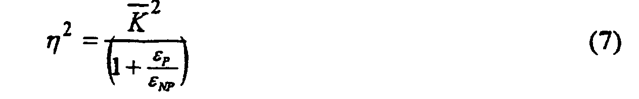
Pour déterminer les conditions d'existence de ces ondes d'interface, examinons les trois termes de l'équation (5). Ces termes doivent être réels et positifs, la vitesse v est donc inférieure ou au plus égale à la plus petite des vitesses vP et vNP. Si v est égale à vNP ≤ vP, le deuxième terme s'annule et lorsque v décroít, les deux premiers termes augmentent. η2 doit donc être supérieur au premier terme lorsque v = vNP.
Les conditions d'existence sont donc données par le couple d'inégalités suivantes :

Le coefficient de couplage 2Δv/v de ces ondes peut être aisément calculé à partir de la vitesse vCC lorsque l'interface est court-circuitée, ou de la vitesse vNC lorsque l'interface n'est pas court-circuitée. Lorsque vNP = vP = vS. On trouve :

| Matériaux | v (m/s) | ρ (kg/m3) | ε | |
| 1 | AIN | 6300 | 3050 | ? |
| 2 | Li2B4O7 | 3000 - 4450 | 2600 | ? |
| 3 | LiNbO3 | 3500 - 4850 | 4700 | 44 |
| 4 | LiTaO3 | 3350 - 4400 | 7450 | 41 |
| 5 | Quartz | 3100 - 3900 | 2651 | 4.5 |
| 6 | ZnO | 2800 | 5680 | 8,55 |
| 7 | PZT | 2450 | 7500 | 1700 |
| 8 | Bi12GeO20 | 1800 | 9200 | ? |
| 9 | Al2O3 | 6200 | 4000 | 9,34 |
| 10 | Si | 5450 | 2332 | 11.7 |
| 11 | YAG | 5100 | 4550 | ? |
| 12 | SiO2 | 3900 | 2050 | 3.78 |
- choisir une orientation des axes cristallographiques du cristal piézoélectrique telle que selon la direction de propagation choisie, l'onde soit purement transversale ou dont la composante transversale du vecteur déplacement 7 soit dominante et telle que cette onde soit piézoélectriquement couplée,
- choisir une orientation des axes cristallographiques du cristal non piézoélectrique telle que selon la direction de propagation choisie, l'onde soit purement transversale ou dont la composante transversale du vecteur déplacement 7 soit dominante et telle que cette onde ait une vitesse de propagation égale ou supérieure à la vitesse des ondes transversales ou quasi-transversale dans le corps piézoélectrique,
- choisir si possible un cristal non piézoélectrique de densité inférieure à celle du cristal piézoélectrique, et
- choisir si possible un cristal non piézoélectrique de constante diélectrique inférieure à celle du cristal piézoélectrique.
Claims (15)
- Filtre acoustique de structure plane dans lequel des ondes acoustiques se propagent sensiblement dans un plan,
caractérisé en ce qu'il comprend deux corps solides (1, 2) dont l'un au moins est piézoélectrique, ces corps étant liés l'un à l'autre de manière à présenter une interface (3) plane entre eux, les ondes acoustiques étant générées par le corps piézoélectrique au moyen d'un champ électrique, et guidées par l'interface entre les deux corps solides, les corps solides étant choisis de manière à ce que ces ondes présentant une énergie acoustique qui décroít exponentiellement dans les deux corps à partir de l'interface dans une direction (Oy) perpendiculaire à l'interface, le vecteur de déplacement des atomes de matière lié à ces ondes se situant dans un plan perpendiculaire à la susdite interface plane (3) séparant les deux corps solides (1,2). - Filtre acoustique selon la revendication 1,
caractérisé en ce que les axes cristallographiques des matériaux constituant les deux corps (1, 2) sont choisis de manière à obtenir à l'interface (3) des ondes acoustiques transversales (SH) ou quasi-transversales (Q-SH), dont le vecteur déplacement (7) présente une seule composante qui est transversale dans le plan de l'interface (3) ou une composante transversale dominante, et que l'onde soit couplée piézoélectriquement - Filtre acoustique selon la revendication 1 ou 2,
caractérisé en ce que les deux corps (1, 2) sont constitués par le même matériau piézoélectrique et sont de mêmes orientations cristallines, de manière à former un seul corps solide à l'intérieur duquel une structure métallique plane (9, 9', 10) formant le filtre, sert de guide piézoélectrique aux ondes acoustiques d'interface transversales (SH) ou quasi-transversales (Q-SH). - Filtre acoustique selon la revendication 3,
caractérisé en ce que les axes cristallographiques du matériau constituant les deux corps solides sont choisis de manière à ce que la composante transversale du vecteur déplacement (7) des ondes acoustiques dans le plan de l'interface (3) soit la seule composante du vecteur déplacement, le matériau étant piézoélectrique de la classe hexagonale 6 mm dont l'axe cristallographique C est dans le plan de l'interface, perpendiculairement à la direction (Ox) de propagation des ondes acoustiques. - Filtre acoustique selon la revendication 3,
caractérisé en ce que les axes cristallographiques du matériau constituant les deux corps (1, 2) sont choisis de manière à ce que la composante transversale du vecteur déplacement (7) des ondes acoustiques dans le plan de l'interface (3) soit dominante, les deux corps étant obtenus en effectuant une coupe suivant l'axe cristallographique Y, cet axe Y étant tourné d'un certain angle, dans du Niobate de Lithium (YX-LiNbO3) ou du Tantalate de Lithium (YX-LiTaO3), les ondes acoustiques se propageant suivant l'axe cristallographique X du matériau. - Filtre acoustique selon la revendication 3,
caractérisé en ce que les axes cristallographiques du matériau constituant les deux corps (1, 2) sont choisis de telle sorte que la composante transversale du vecteur déplacement (7) des ondes acoustiques dans le plan de l'interface (3) soit dominante, les deux corps étant obtenus en effectuant des coupes suivant l'axe cristallographique ST du quartz (ST-X quartz), les ondes acoustiques se propageant suivant l'axe cristallographique X du matériau. - Filtre acoustique selon l'une des revendications 3 à 6,
caractérisé en ce qu'il est obtenu à partir d'un cristal piézoélectrique unique qui a été coupé selon un plan contenant l'axe de propagation (Ox) des ondes acoustiques et l'axe du vecteur déplacement (7) transverse unique (SH) ou dominant (Q-SH) des ondes acoustiques d'interface transversales ou quasi-transversales choisies, la surface obtenue par la coupe de l'une des parties du cristal ainsi coupé comprenant des sillons gravés d'épaisseur contrôlée, dans lesquels est formée une structure métallique plane (9, 9', 10) de filtre, les deux parties coupées (1, 2) ayant été replacées l'une par rapport à l'autre suivant les mêmes orientations cristallines, et fixées l'une à l'autre au moyen d'une adhérence élastique. - Filtre acoustique selon la revendication 1 ou 2,
caractérisé en ce que l'un (1) des corps (1, 2) est piézoélectrique et l'autre (2) est non piézoélectrique, les matériaux constituant les corps (1, 2) étant choisis de manière à ce que la vitesse de propagation des ondes acoustiques transversales ou quasi transversales dans un plan parallèle au plan d'interface (3) dans le matériau non piézoélectrique soit égale ou supérieure à celle dans le matériau piézoélectrique. - Filtre acoustique selon la revendication 8,
caractérisé en ce que la constante diélectrique et la densité du matériau non piézoélectrique sont inférieures à la constante diélectrique et à la densité du matériau piézoélectrique. - Filtre acoustique selon la revendication 8 ou 9,
caractérisé en ce que pour satisfaire les conditions d'existence des ondes acoustiques d'interface (Q-SH) dont la composante transversale du vecteur déplacement (7) dans le plan de l'interface soit dominante, le cristal d'un des deux corps (1, 2) est tourné légèrement par rapport à l'autre autour d'un axe perpendiculaire au plan de leur interface (3) depuis les orientations cristallines nécessaires pour que les ondes piézoélectriques soient purement transversales (SH) à l'interface (3) entre les deux corps (1, 2). - Filtre acoustique selon l'une des revendications 8 à 10,
caractérisé en ce que les deux corps (1, 2) sont obtenus à partir de la coupe de deux matériaux cristallins (A, B) selon des axes cristallographiques adéquats, la surface de l'un des matériaux formant ladite interface (3) comprenant une structure métallique plane (9, 9', 10) de filtre, les deux corps étant fixés l'un à l'autre selon des axes adéquats au moyen d'un procédé d'adhérence élastique. - Filtre acoustique selon l'une des revendications 8 à 11,
caractérisé en ce que le corps non piézoélectrique (2) est un cristal de YAG, tandis que le corps piézoélectrique (1) est un cristal de Niobate de Lithium (YX-LiNbO3) ou un cristal de Tantalate de Lithium (YX-LiTaO3), de coupe suivant l'axe cristallographique Y, la propagation se faisant suivant l'axe cristallographique X, les deux corps étant fixés l'un à l'autre selon les axes adéquats au moyen de tout procédé d'adhérence élastique. - Filtre acoustique selon l'une des revendications 8 à 11,
caractérisé en ce qu'il est formé par un matériau cristallin dont une surface comprend une structure métallique plane de filtre, l'autre corps étant formé sur cette surface par dépôt ou épitaxie selon les axes adéquats. - Filtre acoustique selon la revendication 13,
caractérisé en ce qu'il est réalisé par dépôt de Silicium amorphe sur une surface de Niobate de Lithium (YX-LiNbO3) de coupe suivant l'axe cristallographique Y, où Y est tourné d'un certain angle, la propagation des ondes acoustiques s'effectuant suivant l'axe cristallographique X. - Filtre acoustique selon la revendication 13,
caractérisé en ce qu'il est réalisé par épitaxie d'une couche de Nitrure d'Aluminium (AlN) sur une surface de Saphir (Al2O3).
Applications Claiming Priority (3)
| Application Number | Priority Date | Filing Date | Title |
|---|---|---|---|
| FR9912992 | 1999-10-15 | ||
| FR9912992A FR2799906B1 (fr) | 1999-10-15 | 1999-10-15 | Filtre a ondes acoustiques d'interface notamment pour les liaisons sans fil |
| PCT/FR2000/002727 WO2001029964A1 (fr) | 1999-10-15 | 2000-09-28 | Filtre a ondes acoustiques d'interface notamment pour les liaisons sans fil |
Publications (2)
| Publication Number | Publication Date |
|---|---|
| EP1222735A1 EP1222735A1 (fr) | 2002-07-17 |
| EP1222735B1 true EP1222735B1 (fr) | 2004-02-25 |
Family
ID=9551074
Family Applications (1)
| Application Number | Title | Priority Date | Filing Date |
|---|---|---|---|
| EP00966253A Revoked EP1222735B1 (fr) | 1999-10-15 | 2000-09-28 | Filtre a ondes acoustiques d'interface notamment pour les liaisons sans fil |
Country Status (7)
| Country | Link |
|---|---|
| US (1) | US6737941B1 (fr) |
| EP (1) | EP1222735B1 (fr) |
| JP (1) | JP4820037B2 (fr) |
| AT (1) | ATE260516T1 (fr) |
| DE (1) | DE60008569T9 (fr) |
| FR (1) | FR2799906B1 (fr) |
| WO (1) | WO2001029964A1 (fr) |
Families Citing this family (25)
| Publication number | Priority date | Publication date | Assignee | Title |
|---|---|---|---|---|
| JPH0628265Y2 (ja) | 1991-01-09 | 1994-08-03 | 木村化工機株式会社 | 積層樹脂材料の開先構造 |
| FR2799906B1 (fr) * | 1999-10-15 | 2002-01-25 | Pierre Tournois | Filtre a ondes acoustiques d'interface notamment pour les liaisons sans fil |
| FR2837636B1 (fr) * | 2002-03-19 | 2004-09-24 | Thales Sa | Dispositif a ondes acoustiques d'interface en tantalate de lithium |
| JP3815424B2 (ja) * | 2002-11-08 | 2006-08-30 | 株式会社村田製作所 | 弾性境界波装置 |
| AU2003289100A1 (en) | 2003-02-10 | 2004-08-30 | Murata Manufacturing Co., Ltd. | Elastic boundary wave device |
| JP4337816B2 (ja) * | 2003-04-18 | 2009-09-30 | 株式会社村田製作所 | 弾性境界波装置 |
| DE10325281B4 (de) * | 2003-06-04 | 2018-05-17 | Snaptrack, Inc. | Elektroakustisches Bauelement und Verfahren zur Herstellung |
| KR100850861B1 (ko) * | 2004-01-19 | 2008-08-06 | 가부시키가이샤 무라타 세이사쿠쇼 | 탄성 경계파 장치 |
| CN100576733C (zh) * | 2004-03-05 | 2009-12-30 | 株式会社村田制作所 | 边界声波器件 |
| JP4497159B2 (ja) * | 2004-04-08 | 2010-07-07 | 株式会社村田製作所 | 弾性境界波フィルタ |
| JP4483865B2 (ja) * | 2004-07-26 | 2010-06-16 | 株式会社村田製作所 | 弾性表面波装置 |
| JP2006203304A (ja) * | 2005-01-18 | 2006-08-03 | Hitachi Media Electoronics Co Ltd | 圧電薄膜共振器及びそれを用いた発振器並びにそれを内蔵した半導体集積回路 |
| US7619347B1 (en) | 2005-05-24 | 2009-11-17 | Rf Micro Devices, Inc. | Layer acoustic wave device and method of making the same |
| WO2007007462A1 (fr) * | 2005-07-14 | 2007-01-18 | Murata Manufacturing Co., Ltd. | Dispositif à ondes limites élastiques et procédé de fabrication correspondant |
| JP4001157B2 (ja) * | 2005-07-22 | 2007-10-31 | 株式会社村田製作所 | 弾性境界波装置 |
| DE102005055870A1 (de) | 2005-11-23 | 2007-05-24 | Epcos Ag | Elektroakustisches Bauelement |
| DE102005055871A1 (de) | 2005-11-23 | 2007-05-24 | Epcos Ag | Elektroakustisches Bauelement |
| CN101454974B (zh) * | 2006-05-30 | 2012-05-30 | 株式会社村田制作所 | 声界面波装置 |
| WO2008035546A1 (fr) * | 2006-09-21 | 2008-03-27 | Murata Manufacturing Co., Ltd. | dispositif À onde SUPERFICIELLE Élastique |
| WO2008044411A1 (fr) * | 2006-10-12 | 2008-04-17 | Murata Manufacturing Co., Ltd. | Dispositif à ondes limites élastiques |
| US7408286B1 (en) * | 2007-01-17 | 2008-08-05 | Rf Micro Devices, Inc. | Piezoelectric substrate for a saw device |
| US8490260B1 (en) | 2007-01-17 | 2013-07-23 | Rf Micro Devices, Inc. | Method of manufacturing SAW device substrates |
| US8384495B2 (en) | 2008-06-06 | 2013-02-26 | Panasonic Corporation | Acoustic wave duplexer |
| JPWO2010016246A1 (ja) * | 2008-08-07 | 2012-01-19 | パナソニック株式会社 | 弾性波素子とこれを用いた電子機器 |
| WO2023176761A1 (fr) * | 2022-03-14 | 2023-09-21 | 株式会社Gaianixx | Élément, dispositif électronique, appareil électronique et système |
Family Cites Families (8)
| Publication number | Priority date | Publication date | Assignee | Title |
|---|---|---|---|---|
| FR2145750A5 (fr) * | 1971-07-09 | 1973-02-23 | Thomson Csf | |
| US4328472A (en) * | 1980-11-03 | 1982-05-04 | United Technologies Corporation | Acoustic guided wave devices |
| US4484098A (en) * | 1983-12-19 | 1984-11-20 | United Technologies Corporation | Environmentally stable lithium niobate acoustic wave devices |
| US5633616A (en) * | 1994-10-07 | 1997-05-27 | Mitsubishi Denki Kabushiki Kaisha | Thin film saw filter including doped electrodes |
| JPH09107264A (ja) * | 1995-10-11 | 1997-04-22 | Toyo Commun Equip Co Ltd | チャネル波局部閉じ込め型圧電振動子およびフィルタ |
| US6046656A (en) * | 1997-05-08 | 2000-04-04 | Kabushiki Kaisha Toshiba | Elastic boundary wave device and method of its manufacture |
| WO1998052279A1 (fr) * | 1997-05-12 | 1998-11-19 | Hitachi, Ltd. | Dispositif a onde elastique |
| FR2799906B1 (fr) * | 1999-10-15 | 2002-01-25 | Pierre Tournois | Filtre a ondes acoustiques d'interface notamment pour les liaisons sans fil |
-
1999
- 1999-10-15 FR FR9912992A patent/FR2799906B1/fr not_active Expired - Lifetime
-
2000
- 2000-09-28 WO PCT/FR2000/002727 patent/WO2001029964A1/fr not_active Ceased
- 2000-09-28 DE DE60008569T patent/DE60008569T9/de active Active
- 2000-09-28 US US10/110,403 patent/US6737941B1/en not_active Expired - Lifetime
- 2000-09-28 JP JP2001531203A patent/JP4820037B2/ja not_active Expired - Fee Related
- 2000-09-28 EP EP00966253A patent/EP1222735B1/fr not_active Revoked
- 2000-09-28 AT AT00966253T patent/ATE260516T1/de not_active IP Right Cessation
Also Published As
| Publication number | Publication date |
|---|---|
| US6737941B1 (en) | 2004-05-18 |
| WO2001029964A1 (fr) | 2001-04-26 |
| EP1222735A1 (fr) | 2002-07-17 |
| ATE260516T1 (de) | 2004-03-15 |
| DE60008569D1 (de) | 2004-04-01 |
| FR2799906B1 (fr) | 2002-01-25 |
| JP4820037B2 (ja) | 2011-11-24 |
| FR2799906A1 (fr) | 2001-04-20 |
| DE60008569T9 (de) | 2005-04-07 |
| DE60008569T2 (de) | 2004-12-16 |
| JP2003512637A (ja) | 2003-04-02 |
Similar Documents
| Publication | Publication Date | Title |
|---|---|---|
| EP1222735B1 (fr) | Filtre a ondes acoustiques d'interface notamment pour les liaisons sans fil | |
| EP2909932B1 (fr) | Transducteur a ondes de volume guidees en surface par des structures d'excitation synchrone | |
| CA2553861C (fr) | Structure resonante hybride | |
| EP3113362B1 (fr) | Dispositif a ondes elastiques de surface comprenant un film piezoelectrique monocristallin et un substrat cristallin, a faibles coefficients viscoelastiques | |
| JP5193051B2 (ja) | 電気音響素子 | |
| EP2301150B1 (fr) | Resonateur hbar a stabilite en temperature elevee | |
| EP2291911B1 (fr) | Résonateur hbar à intégration élevée | |
| EP2351214B1 (fr) | Elements de filtres par couplage transverse sur structures resonantes a ondes de volume a resonances harmoniques multiples | |
| FR2785473A1 (fr) | Filtre faibles pertes a ondes acoustiques de surface sur substrat de quartz de coupe optimisee | |
| EP4409743B1 (fr) | Filtre à ondes élastiques de surface et à cavités résonantes | |
| EP1500191B1 (fr) | Dispositif a ondes acoustiques d' interface en tantalate de li thium | |
| WO2022063231A1 (fr) | Dispositifs à ondes acoustiques de surface dotés de transducteurs ultra-minces | |
| EP0116800B1 (fr) | Structure épitaxiale à effet piézoélectrique exalté, et dispositif électronique à ondes acoustiques de surface comportant une telle structure | |
| EP0369835B1 (fr) | Transducteur interdigité pour filtre à ondes de surface | |
| EP3032742B1 (fr) | Dispositif de capteur à ondes élastiques de surface interrogable à distance | |
| WO2014079912A1 (fr) | Transducteur à ondes élastiques de surface se propageant sur un substrat en niobate de lithium ou en tantalate de lithium | |
| WO2025141195A1 (fr) | Dispositif à ondes élastiques | |
| WO2025141194A1 (fr) | Dispositif à ondes élastiques | |
| FR3158014A1 (fr) | Dispositif à ondes élastiques | |
| WO2025141199A1 (fr) | Dispositif à ondes élastiques | |
| WO2025141201A1 (fr) | Dispositif à ondes élastiques | |
| WO2025141196A2 (fr) | Dispositif à ondes élastiques | |
| WO2023222282A1 (fr) | Dispositif a ondes acoustiques de surface integrant une couche mince de materiau metallique |
Legal Events
| Date | Code | Title | Description |
|---|---|---|---|
| PUAI | Public reference made under article 153(3) epc to a published international application that has entered the european phase |
Free format text: ORIGINAL CODE: 0009012 |
|
| 17P | Request for examination filed |
Effective date: 20020412 |
|
| AK | Designated contracting states |
Kind code of ref document: A1 Designated state(s): AT BE CH CY DE DK ES FI FR GB GR IE IT LI LU MC NL PT SE |
|
| AX | Request for extension of the european patent |
Free format text: AL;LT;LV;MK;RO;SI |
|
| 17Q | First examination report despatched |
Effective date: 20021219 |
|
| GRAP | Despatch of communication of intention to grant a patent |
Free format text: ORIGINAL CODE: EPIDOSNIGR1 |
|
| GRAS | Grant fee paid |
Free format text: ORIGINAL CODE: EPIDOSNIGR3 |
|
| GRAA | (expected) grant |
Free format text: ORIGINAL CODE: 0009210 |
|
| AK | Designated contracting states |
Kind code of ref document: B1 Designated state(s): AT BE CH CY DE DK ES FI FR GB GR IE IT LI LU MC NL PT SE |
|
| PG25 | Lapsed in a contracting state [announced via postgrant information from national office to epo] |
Ref country code: IT Free format text: LAPSE BECAUSE OF FAILURE TO SUBMIT A TRANSLATION OF THE DESCRIPTION OR TO PAY THE FEE WITHIN THE PRESCRIBED TIME-LIMIT;WARNING: LAPSES OF ITALIAN PATENTS WITH EFFECTIVE DATE BEFORE 2007 MAY HAVE OCCURRED AT ANY TIME BEFORE 2007. THE CORRECT EFFECTIVE DATE MAY BE DIFFERENT FROM THE ONE RECORDED. Effective date: 20040225 Ref country code: FI Free format text: LAPSE BECAUSE OF FAILURE TO SUBMIT A TRANSLATION OF THE DESCRIPTION OR TO PAY THE FEE WITHIN THE PRESCRIBED TIME-LIMIT Effective date: 20040225 Ref country code: CY Free format text: LAPSE BECAUSE OF FAILURE TO SUBMIT A TRANSLATION OF THE DESCRIPTION OR TO PAY THE FEE WITHIN THE PRESCRIBED TIME-LIMIT Effective date: 20040225 Ref country code: GB Free format text: LAPSE BECAUSE OF FAILURE TO SUBMIT A TRANSLATION OF THE DESCRIPTION OR TO PAY THE FEE WITHIN THE PRESCRIBED TIME-LIMIT Effective date: 20040225 Ref country code: NL Free format text: LAPSE BECAUSE OF FAILURE TO SUBMIT A TRANSLATION OF THE DESCRIPTION OR TO PAY THE FEE WITHIN THE PRESCRIBED TIME-LIMIT Effective date: 20040225 Ref country code: AT Free format text: LAPSE BECAUSE OF FAILURE TO SUBMIT A TRANSLATION OF THE DESCRIPTION OR TO PAY THE FEE WITHIN THE PRESCRIBED TIME-LIMIT Effective date: 20040225 Ref country code: IE Free format text: LAPSE BECAUSE OF FAILURE TO SUBMIT A TRANSLATION OF THE DESCRIPTION OR TO PAY THE FEE WITHIN THE PRESCRIBED TIME-LIMIT Effective date: 20040225 |
|
| REG | Reference to a national code |
Ref country code: GB Ref legal event code: FG4D Free format text: NOT ENGLISH |
|
| REG | Reference to a national code |
Ref country code: CH Ref legal event code: EP |
|
| REG | Reference to a national code |
Ref country code: IE Ref legal event code: FG4D Free format text: FRENCH |
|
| REF | Corresponds to: |
Ref document number: 60008569 Country of ref document: DE Date of ref document: 20040401 Kind code of ref document: P |
|
| REG | Reference to a national code |
Ref country code: CH Ref legal event code: NV Representative=s name: BUGNION S.A. |
|
| PG25 | Lapsed in a contracting state [announced via postgrant information from national office to epo] |
Ref country code: DK Free format text: LAPSE BECAUSE OF FAILURE TO SUBMIT A TRANSLATION OF THE DESCRIPTION OR TO PAY THE FEE WITHIN THE PRESCRIBED TIME-LIMIT Effective date: 20040525 Ref country code: GR Free format text: LAPSE BECAUSE OF FAILURE TO SUBMIT A TRANSLATION OF THE DESCRIPTION OR TO PAY THE FEE WITHIN THE PRESCRIBED TIME-LIMIT Effective date: 20040525 Ref country code: SE Free format text: LAPSE BECAUSE OF FAILURE TO SUBMIT A TRANSLATION OF THE DESCRIPTION OR TO PAY THE FEE WITHIN THE PRESCRIBED TIME-LIMIT Effective date: 20040525 |
|
| PG25 | Lapsed in a contracting state [announced via postgrant information from national office to epo] |
Ref country code: ES Free format text: LAPSE BECAUSE OF FAILURE TO SUBMIT A TRANSLATION OF THE DESCRIPTION OR TO PAY THE FEE WITHIN THE PRESCRIBED TIME-LIMIT Effective date: 20040605 |
|
| NLV1 | Nl: lapsed or annulled due to failure to fulfill the requirements of art. 29p and 29m of the patents act | ||
| GBV | Gb: ep patent (uk) treated as always having been void in accordance with gb section 77(7)/1977 [no translation filed] |
Effective date: 20040225 |
|
| LTIE | Lt: invalidation of european patent or patent extension |
Effective date: 20040225 |
|
| REG | Reference to a national code |
Ref country code: IE Ref legal event code: FD4D |
|
| PG25 | Lapsed in a contracting state [announced via postgrant information from national office to epo] |
Ref country code: LU Free format text: LAPSE BECAUSE OF NON-PAYMENT OF DUE FEES Effective date: 20040928 |
|
| PG25 | Lapsed in a contracting state [announced via postgrant information from national office to epo] |
Ref country code: BE Free format text: LAPSE BECAUSE OF NON-PAYMENT OF DUE FEES Effective date: 20040930 Ref country code: MC Free format text: LAPSE BECAUSE OF NON-PAYMENT OF DUE FEES Effective date: 20040930 |
|
| PLBI | Opposition filed |
Free format text: ORIGINAL CODE: 0009260 |
|
| PLAX | Notice of opposition and request to file observation + time limit sent |
Free format text: ORIGINAL CODE: EPIDOSNOBS2 |
|
| 26 | Opposition filed |
Opponent name: DR. TAM AXEL VON BUELOW Effective date: 20041123 |
|
| BERE | Be: lapsed |
Owner name: *TOURNOIS PIERRE Effective date: 20040930 |
|
| PLAX | Notice of opposition and request to file observation + time limit sent |
Free format text: ORIGINAL CODE: EPIDOSNOBS2 |
|
| PLBB | Reply of patent proprietor to notice(s) of opposition received |
Free format text: ORIGINAL CODE: EPIDOSNOBS3 |
|
| BERE | Be: lapsed |
Owner name: *TOURNOIS PIERRE Effective date: 20040930 |
|
| PG25 | Lapsed in a contracting state [announced via postgrant information from national office to epo] |
Ref country code: PT Free format text: LAPSE BECAUSE OF NON-PAYMENT OF DUE FEES Effective date: 20040725 |
|
| PGFP | Annual fee paid to national office [announced via postgrant information from national office to epo] |
Ref country code: CH Payment date: 20080930 Year of fee payment: 9 |
|
| PLAB | Opposition data, opponent's data or that of the opponent's representative modified |
Free format text: ORIGINAL CODE: 0009299OPPO |
|
| REG | Reference to a national code |
Ref country code: CH Ref legal event code: PL |
|
| PG25 | Lapsed in a contracting state [announced via postgrant information from national office to epo] |
Ref country code: LI Free format text: LAPSE BECAUSE OF NON-PAYMENT OF DUE FEES Effective date: 20090930 Ref country code: CH Free format text: LAPSE BECAUSE OF NON-PAYMENT OF DUE FEES Effective date: 20090930 |
|
| PLAY | Examination report in opposition despatched + time limit |
Free format text: ORIGINAL CODE: EPIDOSNORE2 |
|
| PLBC | Reply to examination report in opposition received |
Free format text: ORIGINAL CODE: EPIDOSNORE3 |
|
| REG | Reference to a national code |
Ref country code: FR Ref legal event code: ST Effective date: 20110531 |
|
| PG25 | Lapsed in a contracting state [announced via postgrant information from national office to epo] |
Ref country code: FR Free format text: LAPSE BECAUSE OF NON-PAYMENT OF DUE FEES Effective date: 20100930 |
|
| PGFP | Annual fee paid to national office [announced via postgrant information from national office to epo] |
Ref country code: FR Payment date: 20091006 Year of fee payment: 10 |
|
| RDAF | Communication despatched that patent is revoked |
Free format text: ORIGINAL CODE: EPIDOSNREV1 |
|
| REG | Reference to a national code |
Ref country code: DE Ref legal event code: R064 Ref document number: 60008569 Country of ref document: DE Ref country code: DE Ref legal event code: R103 Ref document number: 60008569 Country of ref document: DE |
|
| APBM | Appeal reference recorded |
Free format text: ORIGINAL CODE: EPIDOSNREFNO |
|
| APBP | Date of receipt of notice of appeal recorded |
Free format text: ORIGINAL CODE: EPIDOSNNOA2O |
|
| APAH | Appeal reference modified |
Free format text: ORIGINAL CODE: EPIDOSCREFNO |
|
| APBQ | Date of receipt of statement of grounds of appeal recorded |
Free format text: ORIGINAL CODE: EPIDOSNNOA3O |
|
| PGFP | Annual fee paid to national office [announced via postgrant information from national office to epo] |
Ref country code: DE Payment date: 20160926 Year of fee payment: 17 |
|
| APBU | Appeal procedure closed |
Free format text: ORIGINAL CODE: EPIDOSNNOA9O |
|
| RAP2 | Party data changed (patent owner data changed or rights of a patent transferred) |
Owner name: EPCOS AG |
|
| RIN2 | Information on inventor provided after grant (corrected) |
Inventor name: EPCOS AG |
|
| RDAG | Patent revoked |
Free format text: ORIGINAL CODE: 0009271 |
|
| STAA | Information on the status of an ep patent application or granted ep patent |
Free format text: STATUS: PATENT REVOKED |
|
| 27W | Patent revoked |
Effective date: 20130309 |