EP1222869B2 - Vorrichtung zum vorbereitenden Zusammensetzen und Zusammensetzen von Oberteil und Schuhleisten - Google Patents
Vorrichtung zum vorbereitenden Zusammensetzen und Zusammensetzen von Oberteil und Schuhleisten Download PDFInfo
- Publication number
- EP1222869B2 EP1222869B2 EP01830135A EP01830135A EP1222869B2 EP 1222869 B2 EP1222869 B2 EP 1222869B2 EP 01830135 A EP01830135 A EP 01830135A EP 01830135 A EP01830135 A EP 01830135A EP 1222869 B2 EP1222869 B2 EP 1222869B2
- Authority
- EP
- European Patent Office
- Prior art keywords
- trolley
- last
- grippers
- machine
- shoe
- Prior art date
- Legal status (The legal status is an assumption and is not a legal conclusion. Google has not performed a legal analysis and makes no representation as to the accuracy of the status listed.)
- Expired - Lifetime
Links
- 238000006073 displacement reaction Methods 0.000 claims description 8
- 230000000284 resting effect Effects 0.000 claims 1
- 239000000853 adhesive Substances 0.000 description 3
- 230000001070 adhesive effect Effects 0.000 description 3
- 239000000126 substance Substances 0.000 description 3
- 238000004026 adhesive bonding Methods 0.000 description 1
- 230000002411 adverse Effects 0.000 description 1
- 230000005540 biological transmission Effects 0.000 description 1
- 230000000903 blocking effect Effects 0.000 description 1
- 230000002452 interceptive effect Effects 0.000 description 1
- 230000002045 lasting effect Effects 0.000 description 1
- 239000010985 leather Substances 0.000 description 1
- 238000004519 manufacturing process Methods 0.000 description 1
- 238000012986 modification Methods 0.000 description 1
- 230000004048 modification Effects 0.000 description 1
- 238000012544 monitoring process Methods 0.000 description 1
- 230000001105 regulatory effect Effects 0.000 description 1
- 230000002441 reversible effect Effects 0.000 description 1
Images


Classifications
-
- A—HUMAN NECESSITIES
- A43—FOOTWEAR
- A43D—MACHINES, TOOLS, EQUIPMENT OR METHODS FOR MANUFACTURING OR REPAIRING FOOTWEAR
- A43D119/00—Driving or controlling mechanisms of shoe machines; Frames for shoe machines
-
- A—HUMAN NECESSITIES
- A43—FOOTWEAR
- A43D—MACHINES, TOOLS, EQUIPMENT OR METHODS FOR MANUFACTURING OR REPAIRING FOOTWEAR
- A43D21/00—Lasting machines
- A43D21/12—Lasting machines with lasting clamps, shoe-shaped clamps, pincers, wipers, stretching straps or the like for forming the toe or heel parts of the last
-
- A—HUMAN NECESSITIES
- A43—FOOTWEAR
- A43D—MACHINES, TOOLS, EQUIPMENT OR METHODS FOR MANUFACTURING OR REPAIRING FOOTWEAR
- A43D21/00—Lasting machines
- A43D21/16—Lasting machines with lasting pincers and toe- or heel-embracing wipers
- A43D21/166—Lasting machines with lasting pincers and toe- or heel-embracing wipers with toe-embracing wipers
-
- A—HUMAN NECESSITIES
- A43—FOOTWEAR
- A43D—MACHINES, TOOLS, EQUIPMENT OR METHODS FOR MANUFACTURING OR REPAIRING FOOTWEAR
- A43D23/00—Single parts for pulling-over or lasting machines
- A43D23/02—Wipers; Sole-pressers; Last-supports; Pincers
- A43D23/025—Last-supports
-
- A—HUMAN NECESSITIES
- A43—FOOTWEAR
- A43D—MACHINES, TOOLS, EQUIPMENT OR METHODS FOR MANUFACTURING OR REPAIRING FOOTWEAR
- A43D23/00—Single parts for pulling-over or lasting machines
- A43D23/02—Wipers; Sole-pressers; Last-supports; Pincers
- A43D23/027—Pincers
Definitions
- the present invention relates to a machine for preassembling and assembling an upper on a shoe-making last.
- processing operations comprise: arranging the upper on the shoe-making last after an insole has previously been associated with the sole of the last, gripping the edges of the upper by means of a multiplicity of grippers mounted around the last, stretching the upper on the last by means of a relative displacement between grippers and last, blocking the upper on the last by means of pressure members, applying an adhesive to the edge of the insole, gradually easing the grip of the grippers on the upper and turning the edge of the upper over the edge of the insole, resulting in the adhesive bonding of the edge of the upper to the insole.
- the grippers In order for the assembly of the upper on the insole to be performed correctly, the grippers have to be positioned around the last in a manner such that their gripping tips, or more specifically the segments that define the respective gripping portions of the tensioning grippers, are mutually aligned at a predetermined distance from the last, reproducing the profile of the latter and exercising a uniform traction along the entire edge of the upper.
- the tensioning grippers comprise a central gripper positioned in alignment with the front part of the shoe-making last and two respective opposing pluralities of lateral grippers.
- each of said pluralities of lateral grippers is borne by a respective support member which, relative to the bearing structure, is movable along a curved trajectory which encompasses the shoe-making, last, so as better to adjust the positioning of the lateral grippers relative to the specific geometry of the last.
- Patent application WO 95/28104 discloses a pulling over and toe lasting machine having a central toe gripper, which is mounted on a base plate, lateral toe grippers and lateral grippers.
- the lateral toe grippers are supported by a support plate which is pivotally mounted on the base plate, whereas the lateral grippers are supported by a different support plate which is in turn pivotally mounted on the former support plate.
- the support plates can be actuated to position the toe lateral grippers and the lateral grippers in a desired relationship with the central gripper and to each other.
- This machine has the drawback that a removal of the lateral grippers, both toe lateral grippers and lateral grippers, is needed to allow the operator to carry out operations of loosening and/or tightening of the securing members that lock the central gripper. Such an operation is necessary to remove the central gripper in case the last has to be substituted with another one having a toe of different shape and width. Moreover, should the operator remove the lateral grippers, a subsequent need of adjusting the lateral grippers position relative to the last would be necessary, with a consequent loosing of time.
- ITMI 1974U22495 discloses a device for simultaneous adjustment of the clamps in a machine for assembling and pre-assembling uppers on lasts in the manufacture of footwear.
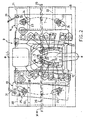
- 1 globally designates a machine according to the invention for the preassembly and assembly of an upper on shoe-making last 3, with the sole of which an insole has been associated.
- the machine 1 comprises a bearing structure 9 to which is fixed a support 4 having a triangular upper surface of limited extent on which the last 3 is intended to bear in alignment with its front part, in other words with its sole.
- the last 3 is supported from below by the triangular surface of the support 4, in a manner such as to present the upper 2 facing upwards, and is positioned in a manner such as to extend from a rear part to a front part along a longitudinal axis (L-L).
- the triangular surface of the support 4 is inclined so that its perpendicular, marked Z-Z, is subvertical and substantially coincides with the line of sight of an operator who, standing in front of the machine 1, is observing the upper surface of said support 4.
- the machine 1 comprises an upper pushing device 7, two opposed lateral pushing devices, both marked 8, and a rear pushing device, not shown in the figures, which are intended to engage respectively with the back, the sides and the heel of the last 3, so as to keep said last in pressing contact against the triangular surface of the support 4 and substantially immobilized in the working position.
- the machine 1 is equipped with tensioning grippers, marked 5, 10 and 11, able to engage the edge of the upper 2 and to pull said upper 2, causing it to adhere to the last 3.
- the abovementioned tensioning grippers are positioned around the support 4 in a manner such as to be substantially facing the contour of the front part of the sole of the last 3, positioned on the support 4.
- the grippers 5, 10 and 11 are of the type described and illustrated in the same applicant's document EP 0 582 027-B1 .
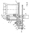
- Each gripper comprises a body which is provided at the upper end with two jaws 33 and is fixed at the lower end to a manipulating rod 12 by means of two arms (not shown) which define a parallelogram linkage system making it possible to cause the opening and closing movements of the jaws 33.
- Each gripper is selectively controlled for opening and closing, and can be selectively displaced in the direction Z-Z by means of appropriate actuating means, so as to obtain the desired tensioning of the leather of the upper 2 on the last 3.
- the tensioning grippers comprise a central gripper 5 positioned along the longitudinal axis L-L in alignment with the front part of the shoe-making last 3 and a first plurality and a second plurality of lateral grippers, respectively marked 10 and 11, opposite one another relative to the longitudinal axis L-L.
- the grippers 5, 10 and 11 are positioned in a manner such as to surround the contour of the front part of the sole of the shoe-making last 3.
- the lateral grippers 10 of the first plurality (that on the left in Figure 2 ) and the lateral grippers 11 of the second plurality (that on the right in Figure 2 ) are mounted on the support member, respectively marked 13 and 14 and movable relative to the bearing structure along a curved trajectory T which encompasses the support 4 on which the shoe-making last 3 is positioned.
- This makes it possible to adjust the positioning of the lateral grippers 10 and 11 of each plurality to the geometry of the shoe-making last 3.
- by moving each support member 13 and 14 it is possible to obtain a simultaneous displacement of all the lateral grippers, 10 and 11 respectively, associated therewith.
- each support member 13, 14 takes the specific form of a substantially flat and rectangular supporting base 15, from the central portion of which extends a vertical wall 16. From the upper end of the vertical wall 16, a bracket 18 extends substantially parallel to a portion of the underlying supporting base 15. The bracket 18, the vertical wall 16 and the supporting base portion covered by the bracket 18 define a C-shaped structure.
- the two support members 13, 14 are disposed in a manner such as to present the respective C-shaped structures facing one another and extending in the direction of the longitudinal axis L-L of the machine 1. In substance, the C formed by each support member 13, 14 is facing the support 4 on which the last 3 is positioned.
- each support member 13, 14 are provided with appropriate respective pluralities of through-holes, one above the other, through which extend the rods 12 on whose upper ends the tensioning grippers 10 and 11 are fixed.
- a pneumatic cylinder 19 Connected to the lower end of each rod 12 is a pneumatic cylinder 19 whereby the vertical movement of said grippers is obtained, intended to ensure the correct tensioning of the upper 2.
- the support member 13 provides operational support for four lateral grippers 10, and an equal number of lateral grippers 11 are supported by the support member 14.
- Each support unit 13, 14 bears, with its base 15, on a working level 6 of the bearing structure 9 disposed perpendicularly to the abovementioned direction Z-Z.
- the working level 6 is thus substantially parallel to the sole of the shoe-making last 3.
- the working level 6 may be replaced by a plurality of crosspieces.
- At least one support member 13, 14, and both in the example shown, is or are mounted on a respective trolley or slide 20, 21, which is movable from and to a remote position in which the respective pluralities of lateral grippers 10, 11 is at a distance from the central gripper 5.
- the machine 1 comprises means for actuating the two trolleys 20, 21 from and to the remote position, in other words from an advanced operating position, in which the lateral grippers 10, 11 are positioned close to the last 3 to a remote position and vice-versa.
- the movement of the two trolleys 20, 21 takes place simultaneously.
- Figure 2 refers to a plan view of the zone of the machine 1 in which the grippers 5, 10, 11, the support members 13, 14 and the two trolleys 20, 21 are present.
- the right-hand half of Figure 2 refers to a situation in which the trolley 21 associated with the support member 13 is in the remote position, while in the left-hand half of the same Figure 2 the trolley 20 associated with the support member 14 is shown in the advanced, operating position.
- Each trolley 20, 21 performs the displacement from the advanced, operating position (shown in the left-hand half of Fig. 2 ) to the remote position (shown in the right-hand half of Fig. 2 ) with a movement having a displacement component transverse to the longitudinal axis L-L.
- this displacement consists of a translatory movement of each of the two trolleys 20, 21 in a direction X-X perpendicular to the longitudinal axis L-L.
- the two trolleys 20, 21, during the movement move away from or towards one another.
- the translatory movement proves to be advantageous to implement from the standpoint of the structural simplicity of the machine 1, though it is possible to impose a rotational or rotational/translatory movement on the two trolleys 20, 21 or, more specifically, on the support members 13 and 14 of the lateral grippers 10, 11.
- each trolley takes the specific form of a plate supported by and shape engaged with sliding guides 22, which extend in the abovementioned direction X-X below the working level 6 and are supported by the bearing structure 9 of the machine 1.
- Each support member 13, 14 is connected to the respective trolley 20, 21 by means of two bolts 23 having the threaded shank extending in the direction Z-Z.
- slots 24 are provided in the base 15 of each support member 13, 14, extending along the abovementioned trajectory T, through which slots the shank of a respective bolt 23 extends.
- the slots 24 may be replaced by a slit of greater length.
- slots 25 are made in alignment with the bolts 23 in the working level 6, through which slots the shanks of the bolts 23 extend.
- the slots 25 extend in the transverse direction X-X.
- the length of the slots and their positioning is such as to allow each trolley 20, 21 the possibility of movement in the manner described above between the advanced, operating position and the remote position, and vice-versa, without the shanks of the bolts 23 interfering with the working level 6.
- the means for actuating the trolleys 20, 21 comprise a threaded bar 26 extending in said transverse direction X-X and pivotably supported in rotation by the bearing structure 9.
- This threaded bar 26 is kinematically associated with an electric motor (not shown) for the rotational actuation thereof and is in screw/nut engagement with a portion, or appendage 27, of each of said trolleys 20, 21. Consequently, one rotation of the threaded bar 26 produces to a translatory movement of the trolleys 20, 21 along the sliding guides 22.
- the threaded bar 26 it is necessary for the threaded bar 26 to have two threaded lengths with opposing threads (right-hand and left-hand), the first of these threaded lengths being in screw/nut engagement with the threaded appendage 27 of the trolley 20 and the other threaded length being in screw/nut engagement with the threaded appendage 27 of the trolley 21.
- the kinematic connection between the shaft of the electric motor and the threaded bar 26 is produced by means of a chain transmission comprising a chain 28 engaging with two pinions 29, 30 respectively keyed on the threaded bar 26 and on the shaft of the electric motor.
- the actuation of the support members 13, 14 along the curved trajectory T is obtained by virtue of respective actuating cylinders, for example of the pneumatic type, which act directly on the base 15 of the support members 13, 14 by means of a manipulating rod 31.
- the machine 1 further comprises means for folding the edge of the upper 2 over onto the sole of the shoe-making last 3, and means for pressing the folded-over edge of the upper 2 from below against the insole, following application of adhesive along the edge of the insole.
- the abovementioned means for folding over the edge of the upper 2 comprise two plates 17, curved so as to encompass the profile of the tip of the last 3 and movable towards said last 3, while the abovementioned means for pressing comprise a plurality of rod-like elements 32 that are movable towards the last 3 in a manner such as to engage it from below with a predetermined elastic force.
- the machine 1 is equipped with means 34 for distributing the adhesive along the contour of the sole of the insole associated with the last 3.
- the machine 1 is additionally equipped with actuating means, regulating and monitoring means, control means and others also necessary to ensure the correct functioning thereof during its working cycle.
- actuating means regulating and monitoring means, control means and others also necessary to ensure the correct functioning thereof during its working cycle.
- control means are known per se and are not described below or shown in the figures.
- the machine according to the invention for the preassembly and assembly of an upper on a shoe-making last makes it possible to meet the above requirement and, at the same time, to overcome the disadvantages to which reference was made in the introductory part of the present description.
Landscapes
- Footwear And Its Accessory, Manufacturing Method And Apparatuses (AREA)
- Automatic Assembly (AREA)
- Vehicle Body Suspensions (AREA)
- Spinning Or Twisting Of Yarns (AREA)
Claims (9)
- Maschine (1) zum Vormontieren und Montieren eines Obermaterials (2) auf einen Schuhleisten, umfassend eine Tragstruktur (9), der Folgendes zugeordnet ist:- Haltemittel (4) zum Positionieren eines Schuhleistens (3) welcher sich zwischen einem vorderen Teil und einem hinteren Teil erstreckt und auf welchem ein Obermaterial (2) gehalten ist, entlang einer Längsachse (L-L);- Mittel (7, 8) zum Angreifen an dem Schuhleisten (3) und Feststellen desselben relativ zu den Haltemitteln (4);- Spanngreifer (5, 10, 11) zum Angreifen am Rand des Obermaterials (2) und zum Ziehen des Obermaterials (2), um es mit dem Schuhleisten (3) zu verkleben, wobei die Spanngreifer (5, 10, 11) so um die Haltemittel (4) herum angeordnet sind, dass sie der Kontur der Sohle des Leistens (3) im Wesentlichen gegenüberliegen, wobei die Spanngreifer einen zentralen Greifer (5), der in Ausrichtung mit dem vorderen Teil des Schuhleistens (3) positioniert ist, und seitliche Greifer (10, 11), welche einander relativ zu der Längsachse (L-L) gegenüberliegen, umfassen,- Betätigungsmittel (19) zum Betätigen der Spanngreifer,- Halteglieder (13, 14) zum Halten der seitlichen Greifer (10, 11), wobei die Halteglieder (13, 14) relativ zu der Tragstruktur (9) entlang einer die Haltemittel (4) umschließenden Bahn bewegbar sind, um die Positionierung der seitlichen Greifer auf die Geometrie des Leistens (3) einzustellen;- weitere Betätigungsmittel (31) zum Betätigen der Halteglieder (13,14),- Mittel (17) zum Umschlagen der Ränder des Obermaterials (2);dadurch gekennzeichnet,- dass die Halteglieder (13, 14) ein erstes Halteglied (13) zum Halten aller seitlichen Greifer (10), welche auf einer Seite relativ zu der Längsachse (L-L) positioniert sind, und ein gegenüberliegendes zweites Halteglied (14) zum Halten aller seitlichen Greifer (11), welche auf der gegenüberliegenden Seite relativ zu der Längsachse (L-L) positioniert sind, umfassen,wobei mindestens eines der beiden Halteglieder (13, 14) auf einem Wagen (20, 21) montiert ist und relativ zu dem Wagen (20, 21) entlang einer gekrümmten Bahn, welche die Haltemittel (4) umschließt, bewegbar ist, wobei der Wagen (20, 21) aus einer Betriebsposition in eine entfernte Position und umgekehrt bewegbar ist, wobei in der Betriebsposition jeweils alle seitlichen Greifer (10, 11) in der Nähe des Leistens (3) positioniert sind und in der entfernten Position jeweils alle seitlichen Greifer (10, 11) von dem zentralen Greifer (5) beabstandet sind, so dass ausreichend Raum für ein zu manipulierendes Werkzeug um den zentralen Greifer (5) herum geschaffen wird.
- Maschine (1) nach Anspruch 1, wobei beide Halteglieder (13, 14) auf einem Wagen montiert sind, der aus einer und in eine entfernte Position, in der die jeweiligen mehreren seitlichen Greifer (10, 11) in einem Abstand von dem zentralen Greifer (5) angeordnet sind, bewegbar ist.
- Maschine (1) nach Anspruch 1 oder 2, wobei die Verschiebung des Wagens (20, 21) aus der und in die entfernte Position mit einer Bewegung stattfindet, die eine zu der Längsachse (L-L) transversale Verschiebungskomponente (A) aufweist.
- Maschine (1) nach Anspruch 3, wobei die Verschiebung des Wagens (20, 21) aus der und in die entfernte Position eine translatorische Bewegung in einer zu der Längsachse (L-L) transversalen Richtung (X-X) umfasst.
- Maschine (1) nach Anspruch 4, wobei der Wagen (20, 21) durch von der Tragstruktur (9) getragene Gleitführungen (22) gleitbeweglich gehalten ist.
- Maschine (1) nach Anspruch 5, wobei die Mittel zum Betätigen des Wagens (20, 21) eine Gewindestange (26) umfassen, welche sich in der transversalen Richtung (X-X) erstreckt und drehbar in Rotation von der Tragstruktur (9) gehalten ist, wobei die Gewindestange (26) kinematisch einem Elektromotor für ihre rotatorische Betätigung zugeordnet ist und in Mutter/Schraub-Verbindung mit einem Bereich (27) des Wagens (20, 21) steht, wobei eine Rotation der Gewindestange (26) eine translatorische Bewegung des Wagens (20, 21) entlang den Gleitführungen (22) erzeugt.
- Maschine (1) nach Anspruch 1, wobei das Halteglied (13, 14) und der Wagen (20, 21) mittels fest an dem Wagen (20, 21) befestigten Bolzen (23) verbunden sind, wobei das Halteglied mit einem Schlitz (24) versehen ist, der in Ausrichtung mit jedem Bolzen (23) steht und eine Relativbewegung des Halteglieds (13, 14) relativ zu dem Bolzen (23) entlang der gekrümmten Bahn (T) erlauben kann.
- Maschine (1) nach Anspruch 7, wobei zwischen dem Halteglied (13, 14) und dem Wagen (20, 21) ein Bereich (6) der Tragstruktur (9) zwischengeschaltet ist, in dem Öffnungen (25) für die Passage der Bolzen herdestellt sind, wobei die Öffnungen (25) ausreichend ausgedehnt sind, um die Bewegung der Bolzen (23) zusammen mit dem Wagen (20, 21) während der Bewegung des Letzteren aus der und in die entfernte Position zu erlauben.
- Maschine (1) nach Anspruch 1, wobei die Mittel zum Positionieren eines Schuhleistens (3) Haltemittel (4) umfassen, welche dazu in der Lage sind, eine Auflagefläche für die Sohle des Schuhleistens (3) bereitzustellen, wobei der Schuhleistens (3) von unten so gehalten wird, dass er das Obermaterial (2) nach oben weisend präsentiert.
Priority Applications (2)
| Application Number | Priority Date | Filing Date | Title |
|---|---|---|---|
| PCT/EP2002/000396 WO2002067711A2 (en) | 2001-01-16 | 2002-01-16 | Machine for preassembling and assembling an upper on a shoe-making last |
| BR0200579-4A BR0200579A (pt) | 2001-01-16 | 2002-01-16 | Máquina para pré-montar e montar uma gáspea em uma fÈrma de fabricação de sapato |
Applications Claiming Priority (2)
| Application Number | Priority Date | Filing Date | Title |
|---|---|---|---|
| WOPCT/IT01/00017 | 2001-01-16 | ||
| IT0100017 | 2001-01-16 |
Publications (3)
| Publication Number | Publication Date |
|---|---|
| EP1222869A1 EP1222869A1 (de) | 2002-07-17 |
| EP1222869B1 EP1222869B1 (de) | 2006-04-26 |
| EP1222869B2 true EP1222869B2 (de) | 2010-01-20 |
Family
ID=11133611
Family Applications (1)
| Application Number | Title | Priority Date | Filing Date |
|---|---|---|---|
| EP01830135A Expired - Lifetime EP1222869B2 (de) | 2001-01-16 | 2001-02-28 | Vorrichtung zum vorbereitenden Zusammensetzen und Zusammensetzen von Oberteil und Schuhleisten |
Country Status (7)
| Country | Link |
|---|---|
| EP (1) | EP1222869B2 (de) |
| AT (1) | ATE324056T1 (de) |
| BR (1) | BR0200579A (de) |
| DE (1) | DE60119073T2 (de) |
| ES (1) | ES2261369T3 (de) |
| HK (1) | HK1046624A1 (de) |
| WO (1) | WO2002067711A2 (de) |
Families Citing this family (3)
| Publication number | Priority date | Publication date | Assignee | Title |
|---|---|---|---|---|
| ITMI20070425A1 (it) * | 2007-03-02 | 2008-09-03 | Elettrotecnica B C Spa | Apparecchiatura per il pre-assemblaggio e l'assemblaggio di una tomaia |
| CN108813821A (zh) * | 2018-08-14 | 2018-11-16 | 华权表 | 一种拖鞋的制造工装及其应用方法 |
| CN115670078B (zh) * | 2022-10-17 | 2025-04-15 | 泉州华数机器人有限公司 | 一种传统鞋楦智能化改造应用的定位工装及方法 |
Family Cites Families (4)
| Publication number | Priority date | Publication date | Assignee | Title |
|---|---|---|---|---|
| US3934294A (en) * | 1974-12-09 | 1976-01-27 | International Shoe Machine Corporation | Lasting machine and method |
| US4380524A (en) * | 1979-04-06 | 1983-04-19 | International Shoe Machine Corporation | Cement applying machine and method |
| DE69207901T2 (de) | 1992-08-07 | 1996-05-30 | Molina & Bianchi Spa | Vorrichtung zum Aufziehen des Schaftes auf einer Leiste mit automatisch eingestelltem Greifer |
| GB9407580D0 (en) * | 1994-04-19 | 1994-06-08 | British United Shoe Machinery | Pulling over and toe lasting machine |
-
2001
- 2001-02-28 DE DE60119073T patent/DE60119073T2/de not_active Expired - Fee Related
- 2001-02-28 ES ES01830135T patent/ES2261369T3/es not_active Expired - Lifetime
- 2001-02-28 AT AT01830135T patent/ATE324056T1/de not_active IP Right Cessation
- 2001-02-28 EP EP01830135A patent/EP1222869B2/de not_active Expired - Lifetime
-
2002
- 2002-01-16 BR BR0200579-4A patent/BR0200579A/pt active Search and Examination
- 2002-01-16 WO PCT/EP2002/000396 patent/WO2002067711A2/en not_active Ceased
- 2002-11-12 HK HK02108194.5A patent/HK1046624A1/en unknown
Also Published As
| Publication number | Publication date |
|---|---|
| ATE324056T1 (de) | 2006-05-15 |
| EP1222869B1 (de) | 2006-04-26 |
| DE60119073T2 (de) | 2006-11-30 |
| WO2002067711A2 (en) | 2002-09-06 |
| EP1222869A1 (de) | 2002-07-17 |
| ES2261369T3 (es) | 2006-11-16 |
| HK1046624A1 (en) | 2003-01-24 |
| BR0200579A (pt) | 2002-11-12 |
| DE60119073D1 (de) | 2006-06-01 |
Similar Documents
| Publication | Publication Date | Title |
|---|---|---|
| EP1222869B2 (de) | Vorrichtung zum vorbereitenden Zusammensetzen und Zusammensetzen von Oberteil und Schuhleisten | |
| DE1510026A1 (de) | Vorheft- und Fersenformmaschine | |
| US3348250A (en) | Machine for pulling over, heel forming and lasting of shoes | |
| EP1036516B1 (de) | Maschine zur Herstellung von Schuhe | |
| US2266774A (en) | Machine for use in operating upon shoe uppers | |
| EP0055107A2 (de) | Maschine zum kombinierten Zwicken der Spitzen und Seitenbereiche von Schuhschäften | |
| EP1661476A1 (de) | Schuhzwickmaschine | |
| US3840929A (en) | Pulling and lasting machines | |
| EP0858745B1 (de) | Klebstoffauftragevorrichtung für die Ränder von Schuhböden | |
| US4520522A (en) | Techniques for stiffening shoe insoles | |
| US3284827A (en) | Apparatus for use in the manufacture of shoes | |
| US4381573A (en) | Shoe upper conforming machine | |
| US3345659A (en) | Lasting machine | |
| US4338695A (en) | Shoe upper conforming machine | |
| DE923653C (de) | Schuhzwickmaschine | |
| EP0124229B1 (de) | Zwickmaschine für Schuhoberleder | |
| US3178742A (en) | Lasting machine | |
| US1188619A (en) | Lasting-machine. | |
| US3660857A (en) | Automatically lasting machines | |
| US542199A (en) | Lasting-machine | |
| DE1927652A1 (de) | Einrichtung und Verfahren zum Formziehen des Schaftes fuer Schuhe | |
| EP1103199A1 (de) | Maschine zum Überholen eines Schuhoberleders über einen Leisten | |
| EP0514349A1 (de) | Vorrichtung zur Abgabe eines Klebstoffes | |
| SU1158155A1 (ru) | Машина дл шнуровой зат жки заготовки верха обуви на колодке | |
| US558043A (en) | Chusetts |
Legal Events
| Date | Code | Title | Description |
|---|---|---|---|
| PUAI | Public reference made under article 153(3) epc to a published international application that has entered the european phase |
Free format text: ORIGINAL CODE: 0009012 |
|
| AK | Designated contracting states |
Kind code of ref document: A1 Designated state(s): AT BE CH CY DE DK ES FI FR GB GR IE IT LI LU MC NL PT SE TR |
|
| AX | Request for extension of the european patent |
Free format text: AL;LT;LV;MK;RO;SI |
|
| 17P | Request for examination filed |
Effective date: 20021111 |
|
| AKX | Designation fees paid |
Designated state(s): AT BE CH CY DE DK ES FI FR GB GR IE IT LI LU MC NL PT SE TR |
|
| 17Q | First examination report despatched |
Effective date: 20040601 |
|
| GRAP | Despatch of communication of intention to grant a patent |
Free format text: ORIGINAL CODE: EPIDOSNIGR1 |
|
| GRAS | Grant fee paid |
Free format text: ORIGINAL CODE: EPIDOSNIGR3 |
|
| GRAA | (expected) grant |
Free format text: ORIGINAL CODE: 0009210 |
|
| AK | Designated contracting states |
Kind code of ref document: B1 Designated state(s): AT BE CH CY DE DK ES FI FR GB GR IE IT LI LU MC NL PT SE TR |
|
| PG25 | Lapsed in a contracting state [announced via postgrant information from national office to epo] |
Ref country code: BE Free format text: LAPSE BECAUSE OF FAILURE TO SUBMIT A TRANSLATION OF THE DESCRIPTION OR TO PAY THE FEE WITHIN THE PRESCRIBED TIME-LIMIT Effective date: 20060426 Ref country code: NL Free format text: LAPSE BECAUSE OF FAILURE TO SUBMIT A TRANSLATION OF THE DESCRIPTION OR TO PAY THE FEE WITHIN THE PRESCRIBED TIME-LIMIT Effective date: 20060426 Ref country code: CH Free format text: LAPSE BECAUSE OF FAILURE TO SUBMIT A TRANSLATION OF THE DESCRIPTION OR TO PAY THE FEE WITHIN THE PRESCRIBED TIME-LIMIT Effective date: 20060426 Ref country code: LI Free format text: LAPSE BECAUSE OF FAILURE TO SUBMIT A TRANSLATION OF THE DESCRIPTION OR TO PAY THE FEE WITHIN THE PRESCRIBED TIME-LIMIT Effective date: 20060426 Ref country code: FI Free format text: LAPSE BECAUSE OF FAILURE TO SUBMIT A TRANSLATION OF THE DESCRIPTION OR TO PAY THE FEE WITHIN THE PRESCRIBED TIME-LIMIT Effective date: 20060426 Ref country code: IT Free format text: LAPSE BECAUSE OF FAILURE TO SUBMIT A TRANSLATION OF THE DESCRIPTION OR TO PAY THE FEE WITHIN THE PRESCRIBED TIME-LIMIT;WARNING: LAPSES OF ITALIAN PATENTS WITH EFFECTIVE DATE BEFORE 2007 MAY HAVE OCCURRED AT ANY TIME BEFORE 2007. THE CORRECT EFFECTIVE DATE MAY BE DIFFERENT FROM THE ONE RECORDED. Effective date: 20060426 |
|
| REG | Reference to a national code |
Ref country code: GB Ref legal event code: FG4D |
|
| REG | Reference to a national code |
Ref country code: IE Ref legal event code: FG4D |
|
| REF | Corresponds to: |
Ref document number: 60119073 Country of ref document: DE Date of ref document: 20060601 Kind code of ref document: P |
|
| PG25 | Lapsed in a contracting state [announced via postgrant information from national office to epo] |
Ref country code: SE Free format text: LAPSE BECAUSE OF FAILURE TO SUBMIT A TRANSLATION OF THE DESCRIPTION OR TO PAY THE FEE WITHIN THE PRESCRIBED TIME-LIMIT Effective date: 20060726 Ref country code: DK Free format text: LAPSE BECAUSE OF FAILURE TO SUBMIT A TRANSLATION OF THE DESCRIPTION OR TO PAY THE FEE WITHIN THE PRESCRIBED TIME-LIMIT Effective date: 20060726 |
|
| REG | Reference to a national code |
Ref country code: PT Ref legal event code: SC4A Effective date: 20060614 |
|
| ET | Fr: translation filed | ||
| REG | Reference to a national code |
Ref country code: CH Ref legal event code: PL |
|
| NLV1 | Nl: lapsed or annulled due to failure to fulfill the requirements of art. 29p and 29m of the patents act | ||
| REG | Reference to a national code |
Ref country code: ES Ref legal event code: FG2A Ref document number: 2261369 Country of ref document: ES Kind code of ref document: T3 |
|
| PLBI | Opposition filed |
Free format text: ORIGINAL CODE: 0009260 |
|
| 26 | Opposition filed |
Opponent name: MARIETTI, ANDREA Effective date: 20070125 |
|
| PG25 | Lapsed in a contracting state [announced via postgrant information from national office to epo] |
Ref country code: MC Free format text: LAPSE BECAUSE OF NON-PAYMENT OF DUE FEES Effective date: 20070228 |
|
| PLAX | Notice of opposition and request to file observation + time limit sent |
Free format text: ORIGINAL CODE: EPIDOSNOBS2 |
|
| PGFP | Annual fee paid to national office [announced via postgrant information from national office to epo] |
Ref country code: PT Payment date: 20070302 Year of fee payment: 7 |
|
| PLAF | Information modified related to communication of a notice of opposition and request to file observations + time limit |
Free format text: ORIGINAL CODE: EPIDOSCOBS2 |
|
| PLBB | Reply of patent proprietor to notice(s) of opposition received |
Free format text: ORIGINAL CODE: EPIDOSNOBS3 |
|
| GBPC | Gb: european patent ceased through non-payment of renewal fee |
Effective date: 20070228 |
|
| PG25 | Lapsed in a contracting state [announced via postgrant information from national office to epo] |
Ref country code: IE Free format text: LAPSE BECAUSE OF NON-PAYMENT OF DUE FEES Effective date: 20070228 |
|
| PG25 | Lapsed in a contracting state [announced via postgrant information from national office to epo] |
Ref country code: GB Free format text: LAPSE BECAUSE OF NON-PAYMENT OF DUE FEES Effective date: 20070228 Ref country code: GR Free format text: LAPSE BECAUSE OF FAILURE TO SUBMIT A TRANSLATION OF THE DESCRIPTION OR TO PAY THE FEE WITHIN THE PRESCRIBED TIME-LIMIT Effective date: 20060727 |
|
| PGFP | Annual fee paid to national office [announced via postgrant information from national office to epo] |
Ref country code: ES Payment date: 20080327 Year of fee payment: 8 Ref country code: FR Payment date: 20070212 Year of fee payment: 7 |
|
| PG25 | Lapsed in a contracting state [announced via postgrant information from national office to epo] |
Ref country code: AT Free format text: LAPSE BECAUSE OF NON-PAYMENT OF DUE FEES Effective date: 20070228 |
|
| REG | Reference to a national code |
Ref country code: PT Ref legal event code: MM4A Free format text: LAPSE DUE TO NON-PAYMENT OF FEES Effective date: 20080901 |
|
| REG | Reference to a national code |
Ref country code: HK Ref legal event code: WD Ref document number: 1046624 Country of ref document: HK |
|
| PG25 | Lapsed in a contracting state [announced via postgrant information from national office to epo] |
Ref country code: PT Free format text: LAPSE BECAUSE OF NON-PAYMENT OF DUE FEES Effective date: 20080901 |
|
| REG | Reference to a national code |
Ref country code: FR Ref legal event code: ST Effective date: 20081031 |
|
| PG25 | Lapsed in a contracting state [announced via postgrant information from national office to epo] |
Ref country code: FR Free format text: LAPSE BECAUSE OF NON-PAYMENT OF DUE FEES Effective date: 20080229 |
|
| PGFP | Annual fee paid to national office [announced via postgrant information from national office to epo] |
Ref country code: DE Payment date: 20090225 Year of fee payment: 9 |
|
| PG25 | Lapsed in a contracting state [announced via postgrant information from national office to epo] |
Ref country code: LU Free format text: LAPSE BECAUSE OF NON-PAYMENT OF DUE FEES Effective date: 20070228 Ref country code: CY Free format text: LAPSE BECAUSE OF FAILURE TO SUBMIT A TRANSLATION OF THE DESCRIPTION OR TO PAY THE FEE WITHIN THE PRESCRIBED TIME-LIMIT Effective date: 20060426 |
|
| PUAH | Patent maintained in amended form |
Free format text: ORIGINAL CODE: 0009272 |
|
| STAA | Information on the status of an ep patent application or granted ep patent |
Free format text: STATUS: PATENT MAINTAINED AS AMENDED |
|
| 27A | Patent maintained in amended form |
Effective date: 20100120 |
|
| AK | Designated contracting states |
Kind code of ref document: B2 Designated state(s): AT BE CH CY DE DK ES FI FR GB GR IE IT LI LU MC NL PT SE TR |
|
| REG | Reference to a national code |
Ref country code: ES Ref legal event code: FD2A Effective date: 20090302 |
|
| PG25 | Lapsed in a contracting state [announced via postgrant information from national office to epo] |
Ref country code: ES Free format text: LAPSE BECAUSE OF NON-PAYMENT OF DUE FEES Effective date: 20090302 |
|
| PG25 | Lapsed in a contracting state [announced via postgrant information from national office to epo] |
Ref country code: DE Free format text: LAPSE BECAUSE OF NON-PAYMENT OF DUE FEES Effective date: 20100901 |
|
| PG25 | Lapsed in a contracting state [announced via postgrant information from national office to epo] |
Ref country code: IT Free format text: LAPSE BECAUSE OF NON-PAYMENT OF DUE FEES Effective date: 20100228 |
|
| PG25 | Lapsed in a contracting state [announced via postgrant information from national office to epo] |
Ref country code: TR Free format text: LAPSE BECAUSE OF NON-PAYMENT OF DUE FEES Effective date: 20110726 |
|
| PGFP | Annual fee paid to national office [announced via postgrant information from national office to epo] |
Ref country code: TR Payment date: 20090225 Year of fee payment: 9 |
|
| PGFP | Annual fee paid to national office [announced via postgrant information from national office to epo] |
Ref country code: IT Payment date: 20110224 Year of fee payment: 11 |
|
| PG25 | Lapsed in a contracting state [announced via postgrant information from national office to epo] |
Ref country code: IT Free format text: LAPSE BECAUSE OF NON-PAYMENT OF DUE FEES Effective date: 20120228 |