EP1222876A2 - Arrangement pour une table ayant au moins deux plateaux - Google Patents
Arrangement pour une table ayant au moins deux plateaux Download PDFInfo
- Publication number
- EP1222876A2 EP1222876A2 EP02000437A EP02000437A EP1222876A2 EP 1222876 A2 EP1222876 A2 EP 1222876A2 EP 02000437 A EP02000437 A EP 02000437A EP 02000437 A EP02000437 A EP 02000437A EP 1222876 A2 EP1222876 A2 EP 1222876A2
- Authority
- EP
- European Patent Office
- Prior art keywords
- control element
- vertical axis
- arrangement according
- central vertical
- tops
- Prior art date
- Legal status (The legal status is an assumption and is not a legal conclusion. Google has not performed a legal analysis and makes no representation as to the accuracy of the status listed.)
- Granted
Links
- 239000011521 glass Substances 0.000 description 4
- 230000005540 biological transmission Effects 0.000 description 3
- 238000006073 displacement reaction Methods 0.000 description 2
- 230000008878 coupling Effects 0.000 description 1
- 238000010168 coupling process Methods 0.000 description 1
- 238000005859 coupling reaction Methods 0.000 description 1
- 230000000694 effects Effects 0.000 description 1
- 230000002996 emotional effect Effects 0.000 description 1
- 239000000463 material Substances 0.000 description 1
- 230000000149 penetrating effect Effects 0.000 description 1
- 239000013641 positive control Substances 0.000 description 1
- 239000007787 solid Substances 0.000 description 1
- 239000000758 substrate Substances 0.000 description 1
- 230000009182 swimming Effects 0.000 description 1
Images


Classifications
-
- A—HUMAN NECESSITIES
- A47—FURNITURE; DOMESTIC ARTICLES OR APPLIANCES; COFFEE MILLS; SPICE MILLS; SUCTION CLEANERS IN GENERAL
- A47B—TABLES; DESKS; OFFICE FURNITURE; CABINETS; DRAWERS; GENERAL DETAILS OF FURNITURE
- A47B13/00—Details of tables or desks
- A47B13/08—Table tops; Rims therefor
- A47B13/088—Sectional table tops
-
- A—HUMAN NECESSITIES
- A47—FURNITURE; DOMESTIC ARTICLES OR APPLIANCES; COFFEE MILLS; SPICE MILLS; SUCTION CLEANERS IN GENERAL
- A47B—TABLES; DESKS; OFFICE FURNITURE; CABINETS; DRAWERS; GENERAL DETAILS OF FURNITURE
- A47B11/00—Tables with tops revolvable on vertical spindles
Definitions
- the invention relates to a table arrangement with at least two table tops, which are arranged to move in different parallel planes are mutually at least in sections in at least one inner position superimpose and by means of a synchronization device are coupled for common movements.
- the object of the invention is a table arrangement of the aforementioned Kind of creating a further improved variability of the Table top arrangement allows.
- the synchronization device with at least one movable planar about a central vertical axis Control is provided by the positive control means on the Table tops exerts spiral control curves such that the table tops between the at least one inner position and at least an outer position in which the table tops have an enlarged joint Represent usable space that can be fanned in or fanned out.
- the mobility of the control element is a flat, two-dimensional one To understand movement. This includes both turning and Swivel movements as well as wobble, pendulum or swimming movements. The movements take place around an imaginary central one Vertical axis, this term should be understood broadly. Because with a wobbling movement repeated for each revolution the control is inevitably constantly eccentric central vertical axis around. Nevertheless, the central vertical axis forms Center around which the control element moves when it wobbles becomes.
- control element is around the central one Vertical axis rotatably mounted. This is an advantageous embodiment to achieve a limited, endless fanning and fanning.
- each table top is a parallelogram steering assigned, with all parallelogram steering have a common central articulation point that is concentric to the central vertical axis is arranged.
- the control element is advantageous only rotatable to a limited extent, preferably by 90 °.
- the parallelogram steering are advantageously arranged so that they are mutually do not hinder.
- the basic idea of this embodiment is with a rotary movement of the control element in the line or straight curved parallel displacements common to all table tops to force outwards or inwards.
- the invention Solution preferably provides that the table tops are relative to each other as well as relative to the central vertical axis Movements while maintaining their parallel alignment in space carry out.
- the table tops move under Maintaining their parallel alignment spirally in space, which makes a particularly harmonious fanning or fanning movement is achievable.
- the one according to the invention is particularly advantageous Solution suitable for three table tops, because then the parallel fanning movement is particularly visually spectacular.
- the table arrangement is preferred Can be used in the coffee table area.
- the rotatable control element designed as a support part in which the table tops with the help of support elements rotatable about pivot axes parallel to the central vertical axis are stored, and the parallelogram steering are with the Support elements connected.
- Feet, base, Columns or legs can be provided, each carrying a table top.
- control element is without a stop rotatable around the central vertical axis. This is advantageous a continuous and endless fanning and fanning can be achieved. The variability when enlarging or reducing the common usable area all table tops compared to the state of the art significantly increased.
- each table top is a positive guide element assigned, which is part of the synchronization device, all the positive guide elements during a rotary movement of the control element revolve like a planet around the central vertical axis. If each table top is held on a single table leg, and each Table leg is assigned a corresponding positive guidance element, this results in the astonishing effect that when the Control element and a resulting fanning or fanning the table tops round the table legs around the central vertical axis.
- control element is eccentric Tumbling movements are movable relative to the central vertical axis. In this way, a continuous and endless fanning and fanning can be achieved.
- the control element advantageously stands with the help of rectified Eccentrics, each assigned to a table top, with the Table tops in active connection. The eccentrics thus create the wobble movements for the control.
- the control element is preferably designed as a flat plate.
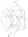
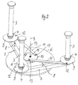
- a table arrangement according to FIGS. 1 and 2 is used in Coffee table area and stands on a solid surface 1.
- the Table arrangement has three rectangular table tops 2, which are preferably can be made of glass.
- Each table top 2 is eccentric to their center and thus to their focus on a support element attached in the form of a columnar foot 3, which by means of a Bearing bush 4 is rotatably mounted in a cover plate 5.
- everyone Foot 3 protrudes through the common cover plate 5, which is also rectangular is designed, through and opens below the cover plate 5 in a carrier part 7 (Fig. 2), in the illustrated embodiment is designed as a stable, open frame.
- the frame 7 does not have two specified legs that are perpendicular to each other according to Art a T-beam are integrally connected.
- the carrier part 7 also has a one-piece, unspecified positioning extension, which by one central vertical axis S, the vertical and coaxial by one shown in Fig. 2 Bearing pin M runs relative to one on the base 1 fixed base plate 6 is rotatably mounted.
- the cover plate 5 is arranged above the carrier part 7 and rotatably connected to the carrier part 7.
- the cover plate 5 of her Bottom ago by means of the screw connections indicated in Fig. 2 8 screwed to the carrier part 7.
- the cover plate 5 and the carrier part 7 serve as a control element in the sense the invention.
- a synchronization device and as a positive guidance device within the meaning of the invention are those described in more detail below Parts 9 to 13 are provided.
- Each foot 3 and thus every table top 2 is in principle in the carrier part 7 as well as in the cover plate 5 a vertical pivot axis parallel to the vertical axis S is rotatably mounted.
- Each foot 3 points above the carrier part 7 and below the Cover plate 5 each have a steering disc 9, which rotatably with the respective Foot 3 is connected.
- On each steering disc 9 engages by means of a Hinge point 12 on a transmission rod 11 to a fixed Crank disk 10, which is aligned concentrically to the vertical axis S. is leads.
- the transmission rod 11 is by means of another hinge point 13 rotatably fixed.
- the Crank disk 10 is firmly connected to the base plate 6, i.e. Likewise arranged stationary.
- the distances of the hinge points 12 to the respective Pivot axis of the associated foot 3 and the distances of the Pivot points 13 on the crank disk 10 to the vertical axis S are identical to each other.
- the straight lines connecting the vertical axis S and the axis of rotation of the inner pivot point 13 of each transmission rod 11 and the pivot axis of the associated foot 3 and the axis of rotation of the outer pivot point 12 are parallel aligned with each other, so that for each foot 3 and thus also results in a parallelogram steering for each table top 2.
- the pivoting angle of the carrier part 7 as well as the cover plate 5 is limited to a maximum of 90 ° by stops not shown in detail.
- the Alignment of the table tops 2 to each other is selected so that the outer edges the table tops 2 are parallel to each other in pairs.
- the cover plate 5 is oriented such that in the inner end position, in which the three table tops 2 the maximum coverage area have, also with their side edges parallel to the outer edges the table tops 2 is aligned. With a beginning twist the top plate 5 and the support member 7 move the table tops 2 while simultaneously rotating outwards about the central vertical axis S, whereby the spiraling fan movements of the table tops 2 result.
- the table tops 2 retain through the positive guidance means in the form of the parallelogram steering described Parallel positions in space, i.e. the assigned outer edges of the Table tops 2 always remain parallel to each other.
- the outer edges of the table tops 2 also parallel to imaginary parallel lines on the substrate 1, whereas the cover plate 5 is relatively to these imaginary parallel lines of the underground, which are fixed in space 1 twist.
- the cover plate 5 In the orientation of the Cover plate 5 has reached the outer end position of the table tops 2, whereby the table tops 2 - seen in plan view - a significantly enlarged have common usable area.
- the table tops 2 can be arranged such that they are also in the fanned out end position overlay each other in sections. However, the arrangement can also be such that there is no overlap in the fanned out end position the table top 2 is more available.
- FIG. 3 and 4 are the inner and outer end positions the table arrangement recognizable.
- Fig. 4 shows that the usable table surface the table tops 2 in the fanned out end position opposite the fanned end position is significantly enlarged.
- each table top in a corner area with an individual Letters A, B, C is in the comparison between the both end positions on the one hand the horizontal displacement of the table tops in the room and on the other hand the spatially rectified parallel shift recognizable because the letters A, B, C in both end positions have the same spatial orientation.
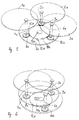
- a table arrangement according to FIGS. 5 and 6 has three circular table tops 1a to 3a, which in the illustrated embodiment Glass exist. Of course, any other is also for the table top suitable material can be used.
- Each table top 1a to 3a is eccentric to their focus and thus eccentric to their center attached to a table leg 4a to 6a, which is perpendicular to Table top protrudes downwards.
- the table legs 4a to 6a are of different heights, so that the Table tops 1a to 3a are in different parallel planes, here located in horizontal planes.
- Each table leg is therefore vertical aligned and in its lower end in a circular Base plate 7a held.
- the base plate 7a also exists in the present case Embodiment made of glass and all three table legs 4a to 6a are rotatably mounted in the common, disc-shaped base plate 7a. All three table legs 4a to 6a point to a center of the circular base plate 7a the same distance. In addition, everyone is three table legs 4a to 6a evenly over the circumference of the foot plate 7a distributed.
- the base plate 7a itself is horizontal by means of a swivel joint 13a rotatably mounted on a fixed base.
- the hinge 13a is positioned concentrically to the center of the foot plate 7a.
- the fixed one Base is through a gear wheel disc described in more detail below 11a and by one on the underside of the gear wheel 11a attached feet 12a formed, which are supported on a surface.
- the gear disc 11a is on its outer edge with a circumferential Provide spur toothing.
- Each rotating table leg 4a to 6a is below the base plate 7a, in which the table legs 4a to 6a are mounted are, a positive guide element 8a to 10a, in the present form a toothed disc with spur gearing, non-rotatable assigned.
- All positive guidance elements 8a to 10a are in the arranged on the same horizontal plane as the fixed gear wheel 11a.
- the spur gears of the positive guide elements 8a to 10a and the gear wheel 11a are coordinated, so that the positive guide elements 8a to 10a with the gear wheel Comb 11a.
- the gear wheel 11a and the positive guide elements 8a to 10a are part of the common synchronizer for a common Movement of the table top 1a to 3a.
- the gear disc 11a and the positive guide elements 10a form the positive guide means in Sense of the invention.
- the footplate serves as the control element 7a.
- the Base plate held stationary. This is the central gear disc rotatable, so that the functions of the gear disc and the Invert the footplate. The table legs then remain on one stationary place. Nevertheless, the desired fanning out or fanning out results.
- both the table tops 1a to 3a and the base plate 7a consist of transparent glass, the parts lying one below the other are not dashed, but shown with solid lines.
- the positive guidance means can in other, not shown embodiments the invention by others, non-positively or positively components which are connected to one another in a force-transmitting manner be educated. So are chain drives or belt drives in particular frictional transfers also provided.
- FIGS. 7 to 9 there are also three Table tops 1 b to 3b eccentrically on each table leg 4b to 6b held.
- a circular control plate 7b serves as the control element, that with the help of rectified eccentrics 10b parallel to one a base plate 11b in its plate plane tumbling around a central, unspecified vertical axis of the Base plate 11b is movably supported.
- the foot plate 11b is at illustrated embodiment also circular and has a smaller diameter than the control plate 7b.
- the lower plate as a wobble control plate and the upper plate, in which the table legs are rotatably supported serves as on the base or base plate is fixed to the ground. This is then by means of corresponding feet supported on the floor to avoid a wobbling Mobility of the control plate below the base or base plate to enable.
- the mode of operation corresponds to that shown here Embodiment in reverse.
- the table legs 4b, 5b, 6b are in the control plate 7b by means of a corresponding Bearings 9b rotatably mounted.
- a tax appendage each Table legs 4b to 6b project downwards through the control plate 7b through and is at a distance from the bearing with the respective eccentric 10b 8b firmly connected.
- the control plate 7b protruding control extension of each table leg 4b to 6b on his lower end on a downward protruding threaded bolt that with an eccentric nut cooperates such that the respective Table leg 4b to 6b is screwed onto the eccentric.
- the control plate In order for a fanning or fanning movement of the table tops 1b to 3b, the control plate is easily in a circumferential direction emotional. This will over the control plate through which penetrate all three table legs 4b to 6b, a torque on the three eccentrics 10b exerted, causing them about their respective axes of rotation in the area of the bearings 8b relative to the fixed lower one Base plate 11b are rotated. Since the table legs 4b to 6b with the eccentrics 10b are firmly connected, they inevitably rotate a rotational movement of the eccentrics 10b inwards or outwards With. To prevent the entire arrangement from locking itself, Of course, all three eccentrics 10b must be parallel to each other be aligned.
Landscapes
- Accommodation For Nursing Or Treatment Tables (AREA)
- Apparatuses For Bulk Treatment Of Fruits And Vegetables And Apparatuses For Preparing Feeds (AREA)
- Confectionery (AREA)
- Apparatus For Radiation Diagnosis (AREA)
Applications Claiming Priority (4)
| Application Number | Priority Date | Filing Date | Title |
|---|---|---|---|
| DE10102400 | 2001-01-12 | ||
| DE2001102400 DE10102400A1 (de) | 2001-01-12 | 2001-01-12 | Tischanordnung mit wenigstens zwei Tischplatten |
| DE2001150397 DE10150397A1 (de) | 2001-10-05 | 2001-10-05 | Tischanordnung mit wenigstens zwei Tischplatten |
| DE10150397 | 2001-10-05 |
Publications (3)
| Publication Number | Publication Date |
|---|---|
| EP1222876A2 true EP1222876A2 (fr) | 2002-07-17 |
| EP1222876A3 EP1222876A3 (fr) | 2002-07-24 |
| EP1222876B1 EP1222876B1 (fr) | 2004-03-24 |
Family
ID=26008284
Family Applications (1)
| Application Number | Title | Priority Date | Filing Date |
|---|---|---|---|
| EP02000437A Expired - Lifetime EP1222876B1 (fr) | 2001-01-12 | 2002-01-08 | Arrangement pour une table ayant au moins deux plateaux |
Country Status (3)
| Country | Link |
|---|---|
| EP (1) | EP1222876B1 (fr) |
| AT (1) | ATE262296T1 (fr) |
| DE (1) | DE50200304D1 (fr) |
Cited By (6)
| Publication number | Priority date | Publication date | Assignee | Title |
|---|---|---|---|---|
| EP1300098A1 (fr) * | 2001-10-05 | 2003-04-09 | Matthias Dipl.-Designer Fischer | Arrangement pour une table ayant au moins deux plateaux |
| EP1437067A1 (fr) * | 2003-01-08 | 2004-07-14 | Casprini Gruppo Industriale S.p.A. | Ensemble de meubles avec deux pièces de meuble qui sont connectées hydrauliquement |
| EP1785057A1 (fr) * | 2005-11-14 | 2007-05-16 | Vel Vega - Design e Tecnologia Ind. Unip. Lda. | Table à au moins deux plateaux |
| CN106213811A (zh) * | 2016-08-31 | 2016-12-14 | 田玉 | 一种多台面茶几 |
| CN107157113A (zh) * | 2017-06-30 | 2017-09-15 | 诺梵(上海)家具科技股份有限公司 | 可旋转多功能圆桌 |
| CN108842324A (zh) * | 2018-07-23 | 2018-11-20 | 王晴 | 一种用于服装绣花工作台的基体结构 |
Citations (1)
| Publication number | Priority date | Publication date | Assignee | Title |
|---|---|---|---|---|
| US5458070A (en) | 1993-04-01 | 1995-10-17 | Naos S.R.L. | Extendible table with two rotating elements, for use as a piece of furniture |
Family Cites Families (4)
| Publication number | Priority date | Publication date | Assignee | Title |
|---|---|---|---|---|
| FR2134839A5 (fr) * | 1971-04-22 | 1972-12-08 | Point Jack | |
| DE9307744U1 (de) * | 1993-05-21 | 1993-07-29 | August Pfister GmbH & Co KG, 8500 Nürnberg | Tisch |
| DE19700538C2 (de) * | 1997-01-10 | 1999-09-02 | Fischer | Möbelstück mit wenigstens zwei exzentrisch drehbar gelagerten Platten |
| DE19901369C2 (de) * | 1999-01-15 | 2002-11-07 | Matthias Fischer | Tischanordnung mit wenigstens zwei Tischplatten |
-
2002
- 2002-01-08 AT AT02000437T patent/ATE262296T1/de not_active IP Right Cessation
- 2002-01-08 DE DE50200304T patent/DE50200304D1/de not_active Expired - Fee Related
- 2002-01-08 EP EP02000437A patent/EP1222876B1/fr not_active Expired - Lifetime
Patent Citations (1)
| Publication number | Priority date | Publication date | Assignee | Title |
|---|---|---|---|---|
| US5458070A (en) | 1993-04-01 | 1995-10-17 | Naos S.R.L. | Extendible table with two rotating elements, for use as a piece of furniture |
Cited By (6)
| Publication number | Priority date | Publication date | Assignee | Title |
|---|---|---|---|---|
| EP1300098A1 (fr) * | 2001-10-05 | 2003-04-09 | Matthias Dipl.-Designer Fischer | Arrangement pour une table ayant au moins deux plateaux |
| EP1437067A1 (fr) * | 2003-01-08 | 2004-07-14 | Casprini Gruppo Industriale S.p.A. | Ensemble de meubles avec deux pièces de meuble qui sont connectées hydrauliquement |
| EP1785057A1 (fr) * | 2005-11-14 | 2007-05-16 | Vel Vega - Design e Tecnologia Ind. Unip. Lda. | Table à au moins deux plateaux |
| CN106213811A (zh) * | 2016-08-31 | 2016-12-14 | 田玉 | 一种多台面茶几 |
| CN107157113A (zh) * | 2017-06-30 | 2017-09-15 | 诺梵(上海)家具科技股份有限公司 | 可旋转多功能圆桌 |
| CN108842324A (zh) * | 2018-07-23 | 2018-11-20 | 王晴 | 一种用于服装绣花工作台的基体结构 |
Also Published As
| Publication number | Publication date |
|---|---|
| EP1222876B1 (fr) | 2004-03-24 |
| DE50200304D1 (de) | 2004-04-29 |
| ATE262296T1 (de) | 2004-04-15 |
| EP1222876A3 (fr) | 2002-07-24 |
Similar Documents
| Publication | Publication Date | Title |
|---|---|---|
| DE3735882C1 (de) | Antrieb fuer einen Drehteller in einer Etikettiermaschine fuer Flaschen | |
| DE102007005136A1 (de) | Schneidvorrichtung | |
| DE69705791T2 (de) | Massagegerät zum einsetzen in die rückenlehne eines massagestuhles | |
| EP2243456B1 (fr) | Table d'opération | |
| EP1222876B1 (fr) | Arrangement pour une table ayant au moins deux plateaux | |
| DE2433954B2 (de) | Handhabungsgeraet | |
| EP1785057B1 (fr) | Table à au moins deux plateaux | |
| DE3206318A1 (de) | Reparatur- und montagetisch fuer vorzugsweise elektrische geraete | |
| DE60200832T2 (de) | Tisch mit mindestens einer lediglich durch drehung ausschwenkbaren verlängerung | |
| DE3144302C2 (de) | Beckenmaschine für Schlagzeuge | |
| DE908339C (de) | Einstellvorrichtung, insbesondere fuer Werkzeugmaschinen bzw. solche Anordnungen, bei denen ein Arbeitskoerper zu einem Tragkoerper Schwenkbewegungen ausfuehrt | |
| DE19700538A1 (de) | Möbelstück mit wenigstens zwei exzentrisch drehbar gelagerten Platten | |
| DE10316246A1 (de) | Möbel, insbesonder Tisch | |
| DE10102400A1 (de) | Tischanordnung mit wenigstens zwei Tischplatten | |
| EP1020137A2 (fr) | Arrangement pour une table ayant au moins deux surfaces de table | |
| DE10150397A1 (de) | Tischanordnung mit wenigstens zwei Tischplatten | |
| DE10150396A1 (de) | Tisch mit einer höhenverlagerbaren Tischplatte | |
| EP1661489A1 (fr) | Meuble avec une surface de support horizontale en état de fonctionnement | |
| EP1787547A1 (fr) | Piece de mobilier á panneau variable | |
| DE1211831B (de) | Selbstverkaeufer zur Ausgabe von zylinderfoermigen Gegenstaenden aus einem oder mehreren nebeneinander angeordneten Schaechten | |
| DE102017103215A1 (de) | Ein Steuerungs- und Kontrolltisch | |
| DE3710406A1 (de) | Spielwerk | |
| DE2154910A1 (de) | Planetärer Zeichentisch | |
| DE2019547A1 (de) | Stufenloses Regelgetriebe | |
| EP0908116A2 (fr) | Table avec un plateau de travail |
Legal Events
| Date | Code | Title | Description |
|---|---|---|---|
| PUAI | Public reference made under article 153(3) epc to a published international application that has entered the european phase |
Free format text: ORIGINAL CODE: 0009012 |
|
| PUAL | Search report despatched |
Free format text: ORIGINAL CODE: 0009013 |
|
| AK | Designated contracting states |
Kind code of ref document: A2 Designated state(s): AT BE CH CY DE DK ES FI FR GB GR IE IT LI LU MC NL PT SE TR |
|
| AX | Request for extension of the european patent |
Free format text: AL;LT;LV;MK;RO;SI |
|
| AK | Designated contracting states |
Kind code of ref document: A3 Designated state(s): AT BE CH CY DE DK ES FI FR GB GR IE IT LI LU MC NL PT SE TR |
|
| AX | Request for extension of the european patent |
Free format text: AL;LT;LV;MK;RO;SI |
|
| RIC1 | Information provided on ipc code assigned before grant |
Free format text: 7A 47B 11/00 A, 7A 47B 13/08 B |
|
| RAP1 | Party data changed (applicant data changed or rights of an application transferred) |
Owner name: MATTHIAS FISCHER DESIGN GMBH |
|
| RIN1 | Information on inventor provided before grant (corrected) |
Inventor name: MATTHIAS FISCHER DESIGN GMBH |
|
| 17P | Request for examination filed |
Effective date: 20021116 |
|
| RIN1 | Information on inventor provided before grant (corrected) |
Inventor name: FISCHER, MATTHIAS, DIPL.-DESIGNER |
|
| AKX | Designation fees paid |
Designated state(s): AT BE CH CY DE DK ES FI FR GB GR IE IT LI LU MC NL PT SE TR |
|
| GRAP | Despatch of communication of intention to grant a patent |
Free format text: ORIGINAL CODE: EPIDOSNIGR1 |
|
| GRAS | Grant fee paid |
Free format text: ORIGINAL CODE: EPIDOSNIGR3 |
|
| GRAA | (expected) grant |
Free format text: ORIGINAL CODE: 0009210 |
|
| AK | Designated contracting states |
Kind code of ref document: B1 Designated state(s): AT BE CH CY DE DK ES FI FR GB GR IE IT LI LU MC NL PT SE TR |
|
| PG25 | Lapsed in a contracting state [announced via postgrant information from national office to epo] |
Ref country code: FI Free format text: LAPSE BECAUSE OF FAILURE TO SUBMIT A TRANSLATION OF THE DESCRIPTION OR TO PAY THE FEE WITHIN THE PRESCRIBED TIME-LIMIT Effective date: 20040324 Ref country code: IE Free format text: LAPSE BECAUSE OF FAILURE TO SUBMIT A TRANSLATION OF THE DESCRIPTION OR TO PAY THE FEE WITHIN THE PRESCRIBED TIME-LIMIT Effective date: 20040324 Ref country code: TR Free format text: LAPSE BECAUSE OF FAILURE TO SUBMIT A TRANSLATION OF THE DESCRIPTION OR TO PAY THE FEE WITHIN THE PRESCRIBED TIME-LIMIT Effective date: 20040324 |
|
| REG | Reference to a national code |
Ref country code: GB Ref legal event code: FG4D Free format text: NOT ENGLISH |
|
| RIN1 | Information on inventor provided before grant (corrected) |
Inventor name: FISCHER, MATTHIAS, DIPL.-DESIGNER |
|
| REG | Reference to a national code |
Ref country code: CH Ref legal event code: EP |
|
| REG | Reference to a national code |
Ref country code: CH Ref legal event code: NV Representative=s name: ZIMMERLI, WAGNER & PARTNER AG |
|
| REG | Reference to a national code |
Ref country code: IE Ref legal event code: FG4D Free format text: GERMAN |
|
| REF | Corresponds to: |
Ref document number: 50200304 Country of ref document: DE Date of ref document: 20040429 Kind code of ref document: P |
|
| PG25 | Lapsed in a contracting state [announced via postgrant information from national office to epo] |
Ref country code: SE Free format text: LAPSE BECAUSE OF FAILURE TO SUBMIT A TRANSLATION OF THE DESCRIPTION OR TO PAY THE FEE WITHIN THE PRESCRIBED TIME-LIMIT Effective date: 20040624 Ref country code: GR Free format text: LAPSE BECAUSE OF FAILURE TO SUBMIT A TRANSLATION OF THE DESCRIPTION OR TO PAY THE FEE WITHIN THE PRESCRIBED TIME-LIMIT Effective date: 20040624 Ref country code: DK Free format text: LAPSE BECAUSE OF FAILURE TO SUBMIT A TRANSLATION OF THE DESCRIPTION OR TO PAY THE FEE WITHIN THE PRESCRIBED TIME-LIMIT Effective date: 20040624 |
|
| PG25 | Lapsed in a contracting state [announced via postgrant information from national office to epo] |
Ref country code: ES Free format text: LAPSE BECAUSE OF FAILURE TO SUBMIT A TRANSLATION OF THE DESCRIPTION OR TO PAY THE FEE WITHIN THE PRESCRIBED TIME-LIMIT Effective date: 20040705 |
|
| GBT | Gb: translation of ep patent filed (gb section 77(6)(a)/1977) |
Effective date: 20040713 |
|
| REG | Reference to a national code |
Ref country code: IE Ref legal event code: FD4D |
|
| ET | Fr: translation filed | ||
| PG25 | Lapsed in a contracting state [announced via postgrant information from national office to epo] |
Ref country code: CY Free format text: LAPSE BECAUSE OF FAILURE TO SUBMIT A TRANSLATION OF THE DESCRIPTION OR TO PAY THE FEE WITHIN THE PRESCRIBED TIME-LIMIT Effective date: 20050108 |
|
| PLBE | No opposition filed within time limit |
Free format text: ORIGINAL CODE: 0009261 |
|
| STAA | Information on the status of an ep patent application or granted ep patent |
Free format text: STATUS: NO OPPOSITION FILED WITHIN TIME LIMIT |
|
| PG25 | Lapsed in a contracting state [announced via postgrant information from national office to epo] |
Ref country code: MC Free format text: LAPSE BECAUSE OF NON-PAYMENT OF DUE FEES Effective date: 20050131 |
|
| 26N | No opposition filed |
Effective date: 20041228 |
|
| PG25 | Lapsed in a contracting state [announced via postgrant information from national office to epo] |
Ref country code: PT Free format text: LAPSE BECAUSE OF NON-PAYMENT OF DUE FEES Effective date: 20040824 |
|
| PGFP | Annual fee paid to national office [announced via postgrant information from national office to epo] |
Ref country code: CH Payment date: 20080124 Year of fee payment: 7 |
|
| PGFP | Annual fee paid to national office [announced via postgrant information from national office to epo] |
Ref country code: DE Payment date: 20080123 Year of fee payment: 7 Ref country code: GB Payment date: 20080123 Year of fee payment: 7 Ref country code: IT Payment date: 20080126 Year of fee payment: 7 Ref country code: LU Payment date: 20080125 Year of fee payment: 7 Ref country code: NL Payment date: 20080124 Year of fee payment: 7 |
|
| PGFP | Annual fee paid to national office [announced via postgrant information from national office to epo] |
Ref country code: AT Payment date: 20080123 Year of fee payment: 7 |
|
| PGFP | Annual fee paid to national office [announced via postgrant information from national office to epo] |
Ref country code: FR Payment date: 20080118 Year of fee payment: 7 |
|
| PGFP | Annual fee paid to national office [announced via postgrant information from national office to epo] |
Ref country code: BE Payment date: 20080123 Year of fee payment: 7 |
|
| REG | Reference to a national code |
Ref country code: CH Ref legal event code: PL |
|
| GBPC | Gb: european patent ceased through non-payment of renewal fee |
Effective date: 20090108 |
|
| NLV4 | Nl: lapsed or anulled due to non-payment of the annual fee |
Effective date: 20090801 |
|
| PG25 | Lapsed in a contracting state [announced via postgrant information from national office to epo] |
Ref country code: AT Free format text: LAPSE BECAUSE OF NON-PAYMENT OF DUE FEES Effective date: 20090108 Ref country code: LI Free format text: LAPSE BECAUSE OF NON-PAYMENT OF DUE FEES Effective date: 20090131 Ref country code: CH Free format text: LAPSE BECAUSE OF NON-PAYMENT OF DUE FEES Effective date: 20090131 Ref country code: DE Free format text: LAPSE BECAUSE OF NON-PAYMENT OF DUE FEES Effective date: 20090801 |
|
| REG | Reference to a national code |
Ref country code: FR Ref legal event code: ST Effective date: 20091030 |
|
| PG25 | Lapsed in a contracting state [announced via postgrant information from national office to epo] |
Ref country code: NL Free format text: LAPSE BECAUSE OF NON-PAYMENT OF DUE FEES Effective date: 20090801 Ref country code: GB Free format text: LAPSE BECAUSE OF NON-PAYMENT OF DUE FEES Effective date: 20090108 |
|
| PG25 | Lapsed in a contracting state [announced via postgrant information from national office to epo] |
Ref country code: BE Free format text: LAPSE BECAUSE OF NON-PAYMENT OF DUE FEES Effective date: 20090131 |
|
| PG25 | Lapsed in a contracting state [announced via postgrant information from national office to epo] |
Ref country code: FR Free format text: LAPSE BECAUSE OF NON-PAYMENT OF DUE FEES Effective date: 20090202 |
|
| PG25 | Lapsed in a contracting state [announced via postgrant information from national office to epo] |
Ref country code: IT Free format text: LAPSE BECAUSE OF NON-PAYMENT OF DUE FEES Effective date: 20090108 |
|
| PG25 | Lapsed in a contracting state [announced via postgrant information from national office to epo] |
Ref country code: LU Free format text: LAPSE BECAUSE OF NON-PAYMENT OF DUE FEES Effective date: 20090108 |