EP1222942A2 - Verfahren und Vorrichtung zur Festsetzung des Einfangens und des Schwellwertes mittels einer Programmiereinrichtung - Google Patents
Verfahren und Vorrichtung zur Festsetzung des Einfangens und des Schwellwertes mittels einer Programmiereinrichtung Download PDFInfo
- Publication number
- EP1222942A2 EP1222942A2 EP02250262A EP02250262A EP1222942A2 EP 1222942 A2 EP1222942 A2 EP 1222942A2 EP 02250262 A EP02250262 A EP 02250262A EP 02250262 A EP02250262 A EP 02250262A EP 1222942 A2 EP1222942 A2 EP 1222942A2
- Authority
- EP
- European Patent Office
- Prior art keywords
- capture
- pacing
- programmer
- stimulation device
- medical practitioner
- Prior art date
- Legal status (The legal status is an assumption and is not a legal conclusion. Google has not performed a legal analysis and makes no representation as to the accuracy of the status listed.)
- Granted
Links
- 238000012795 verification Methods 0.000 title claims abstract description 80
- 238000000034 method Methods 0.000 title claims abstract description 41
- 208000033988 Device pacing issue Diseases 0.000 title claims abstract description 34
- 230000000638 stimulation Effects 0.000 claims abstract description 132
- 230000000747 cardiac effect Effects 0.000 claims abstract description 55
- 238000012552 review Methods 0.000 claims abstract description 9
- 230000002861 ventricular Effects 0.000 claims description 32
- 230000001746 atrial effect Effects 0.000 claims description 31
- 230000000007 visual effect Effects 0.000 claims description 25
- 239000003550 marker Substances 0.000 claims description 14
- 230000003213 activating effect Effects 0.000 claims 1
- 238000012360 testing method Methods 0.000 abstract description 28
- 238000004458 analytical method Methods 0.000 abstract description 11
- 230000006870 function Effects 0.000 description 18
- 238000004891 communication Methods 0.000 description 17
- 208000033986 Device capturing issue Diseases 0.000 description 7
- 238000001514 detection method Methods 0.000 description 7
- 238000013461 design Methods 0.000 description 6
- 230000004936 stimulating effect Effects 0.000 description 6
- 230000008901 benefit Effects 0.000 description 4
- 238000010586 diagram Methods 0.000 description 4
- 229940079593 drug Drugs 0.000 description 4
- 239000003814 drug Substances 0.000 description 4
- 230000000694 effects Effects 0.000 description 4
- 210000002837 heart atrium Anatomy 0.000 description 4
- 230000004044 response Effects 0.000 description 4
- 230000001225 therapeutic effect Effects 0.000 description 4
- 206010003119 arrhythmia Diseases 0.000 description 3
- 238000013500 data storage Methods 0.000 description 3
- 230000009471 action Effects 0.000 description 2
- 238000013459 approach Methods 0.000 description 2
- 230000008859 change Effects 0.000 description 2
- 230000008602 contraction Effects 0.000 description 2
- 230000000763 evoking effect Effects 0.000 description 2
- 238000002513 implantation Methods 0.000 description 2
- 230000007774 longterm Effects 0.000 description 2
- 238000002483 medication Methods 0.000 description 2
- 238000012544 monitoring process Methods 0.000 description 2
- 230000010287 polarization Effects 0.000 description 2
- 238000012545 processing Methods 0.000 description 2
- 230000003068 static effect Effects 0.000 description 2
- 210000001519 tissue Anatomy 0.000 description 2
- 208000001871 Tachycardia Diseases 0.000 description 1
- 208000006218 bradycardia Diseases 0.000 description 1
- 230000036471 bradycardia Effects 0.000 description 1
- 230000001684 chronic effect Effects 0.000 description 1
- 238000004590 computer program Methods 0.000 description 1
- 210000001308 heart ventricle Anatomy 0.000 description 1
- 230000010365 information processing Effects 0.000 description 1
- 230000000977 initiatory effect Effects 0.000 description 1
- 238000005259 measurement Methods 0.000 description 1
- 210000003205 muscle Anatomy 0.000 description 1
- 210000004165 myocardium Anatomy 0.000 description 1
- 230000003287 optical effect Effects 0.000 description 1
- 230000000737 periodic effect Effects 0.000 description 1
- 230000008569 process Effects 0.000 description 1
- 230000033764 rhythmic process Effects 0.000 description 1
- 229920006395 saturated elastomer Polymers 0.000 description 1
- 238000004904 shortening Methods 0.000 description 1
- 238000004088 simulation Methods 0.000 description 1
- 210000002027 skeletal muscle Anatomy 0.000 description 1
- 238000010998 test method Methods 0.000 description 1
- 238000002560 therapeutic procedure Methods 0.000 description 1
- 230000008467 tissue growth Effects 0.000 description 1
Images

Classifications
-
- A—HUMAN NECESSITIES
- A61—MEDICAL OR VETERINARY SCIENCE; HYGIENE
- A61N—ELECTROTHERAPY; MAGNETOTHERAPY; RADIATION THERAPY; ULTRASOUND THERAPY
- A61N1/00—Electrotherapy; Circuits therefor
- A61N1/18—Applying electric currents by contact electrodes
- A61N1/32—Applying electric currents by contact electrodes alternating or intermittent currents
- A61N1/36—Applying electric currents by contact electrodes alternating or intermittent currents for stimulation
- A61N1/362—Heart stimulators
- A61N1/37—Monitoring; Protecting
- A61N1/371—Capture, i.e. successful stimulation
Definitions
- the present invention relates in general to implantable cardiac stimulation devices, including bradycardia and anti-tachycardia implantable stimulation devices, defibrillators, cardioverters and combinations thereof that are capable of measuring, storing, and transmitting physiological data and parametric data pertaining to implantable medical devices. More particularly, this invention relates to a system and method for automating the threshold assessment process by utilizing a programmer device with specialized software for the purpose of assessing capture verification in conjunction with an implantable cardiac stimulation device.
- Implantable medical devices such as implantable stimulation devices, defibrillators, and cardioverters (collectively referred to as implantable cardiac stimulating devices) are designed to monitor and stimulate the heart of a patient that suffers from a cardiac arrhythmia. Using leads in contact with a patient's heart, these devices typically stimulate the cardiac muscles by delivering electrical pulses in response to detection of cardiac events, which are indicative of a cardiac arrhythmia. Properly administered therapeutic electrical pulses often successfully reestablish or maintain the heart's regular rhythm.
- Implantable cardiac stimulating devices can treat a wide range of cardiac arrhythmias by using a series of adjustable parameters to alter the stimulus energy, the shape, the location, and the frequency of the therapeutic pulses.
- the adjustable parameters are usually defined in a computer program stored in a memory of the implantable device.
- the program (which is responsible for the operation of the implantable device) can be defined or altered telemetrically by a medical practitioner using an implantable device programmer.
- Modern implantable devices have a great number of adjustable parameters that must be tailored to a particular patient's therapeutic needs.
- Capture is defined as a cardiac response to an implantable stimulation device stimulation pulse.
- Capture threshold is generally defined as a minimum amount of stimulation energy to effect capture. Capture should be achieved at the lowest possible energy setting yet provide enough of a safety margin so that should a patient's threshold increase, the output of an implantable stimulation device (i.e. the pacing stimulus energy) would be sufficient to maintain capture.
- Dual-chamber implantable stimulation devices may have differing atrial and ventricular pacing thresholds that correspond to atrial and ventricular capture thresholds, respectively.
- the earliest implantable stimulation devices had a predetermined and unchangeable pacing stimulus energy, which proved to be problematic because the capture threshold is not a static value.
- the capture threshold may be affected by a variety of physiological and other factors. For example, certain cardiac medications may temporarily raise or lower the capture threshold from its normal value. In another example, fibrous tissue that forms around implantable stimulation device lead tips within several weeks after implantation may raise the capture threshold. As a result, some patients eventually suffered from loss of capture as their implantable stimulation devices were unable to adjust the pre-set pacing stimulus energies to overcome the changed capture thresholds.
- One solution was to set the level of stimulation energy fairly high so as to provide sufficient safety margin and avoid loss of capture due to a change in the capture threshold. However, this approach resulted in some discomfort from skeletal muscle stimulation in patients who had to endure high levels of cardiac stimulation energy. Furthermore, such stimulation pulses consumed extra battery resources, thus shortening the useful life of an implantable stimulation device.
- the pacing stimulus energy was implemented as an adjustable parameter that could be set or changed by a medical practitioner.
- adjustments were made by the medical practitioner using an external programmer capable of communication with an implanted implantable stimulation device via telemetry through a programming wand applied to a patient's chest.
- Pulsed magnetic fields applied over the implantable stimulation device were also used to modify pacing parameters.
- the particular setting for the implantable stimulation device's stimulus energy was usually derived from results of extensive physiological tests performed by the medical practitioner to determine the patient's capture threshold, from the patient's medical history, and from the patient's list of medications.
- the stimulus energy setting required consideration of the capture threshold and safety margin.
- the adjustable pacing stimulus energy feature proved to be superior to the previously known static stimulus energy, some significant problems remained unsolved. In particular, when a patient's capture threshold changed, the patient was forced to visit the medical practitioner to adjust the pacing stimulus energy accordingly.
- implantable stimulation device manufacturers have developed advanced implantable stimulation devices that are capable of determining a patient's capture threshold and automatically adjusting the stimulation pulses to a level just above that which is needed to maintain capture.
- This approach referred herein as “autocapture” improves the patient's comfort, reduces the necessity of unscheduled visits to the medical practitioner, improves patient safety, and greatly increases the implantable stimulation device's battery life by conserving the energy used for stimulation pulses.
- an implantable stimulation device maintains a record of each threshold assessment and the resulting stimulus energy required to maintain capture. This record keeping by the implantable stimulation device is of benefit to the medical practitioner in that it provides a record of lead stability and chronic performance.
- capture may be verified by analyzing cardiac signals and comparing them to a polarization template and then determining the presence of an evoked response, as is disclosed in commonly assigned U.S. Patent No. 5,417,718 (Kleks et al.), and which is hereby incorporated herein by reference.
- capture assessment may take place by assessing mechanical changes in the heart associated with a contraction, such as the motion of a cardiac wall or by direct detection and measurement of the cardiac evoked response immediately following a pacing pulse, as is disclosed in commonly assigned U.S. Patent No. 5,549,652 (McClure et al.), which is also hereby incorporated herein by reference.
- the pacing stimulus energy is then automatically set at a level just above that necessary to maintain capture. As the patient's capture threshold changes, the pacing stimulus energy is correspondingly automatically adjusted.
- the medical practitioner After initial implantation and configuration of the implantable stimulation device, the medical practitioner typically performs periodic follow-up examinations to determine if the therapy delivered by the device is having the desired effect and the implantable stimulation device is otherwise operating properly. In particular, it is of utmost importance to verify that the implantable stimulation device's pacing stimulus energy is sufficient to maintain capture with an adequate safety margin to consider changes in capture threshold.
- the capture threshold may change over time as a result of a variety of factors, such as fibrous tissue growth on implantable stimulation device lead tips or the regimen of the patient's medication. Such changes in the capture threshold may have caused loss of capture in an older implantable stimulation device model. Thus, the medical practitioner must determine whether capture is present, whether there is sufficient stimulus safety margin, and when capture is not present, adjust the pacing stimulus energy to reestablish capture.
- a system and method that is initiated by a medical practitioner, are provided for automating the pacing threshold assessment procedure and capture verification by the stimulation device or by the programmer of proper capture by stimulus pulses from a patient's implantable cardiac stimulation device, and to automatically adjust the device's pacing stimulus energy if necessary.
- the system and method of the present invention also utilize information processing, markers & other annotation and output capabilities of an implantable device programmer to enable the medical practitioner to observe the automatic procedure and to verify that it is performed properly.
- the programmer may also be used to initiate and observe the pacing threshold assessment with automatic capture verification procedure for implantable stimulation devices that do not inherently by design possess the self-determinant capability of morphology detection to determine capture.
- the programmer may also be used to remotely initiate and assess capture verification and provide a threshold assessment when the patient is at a different geographic location than the medical practitioner.
- the system and method of this invention may also automatically document the capture threshold and make recommendations for adjusting the proper stimulus energy level. All of the aforementioned advantages and features are achieved without incurring any substantial relative disadvantage.
- the present invention provides an implantable cardiac stimulation device equipped with data acquisition and telemetric communication capabilities, and also provides an implantable device programmer, preferably in the form of a portable computer, with data processing, data storage, graphical data display, data output, data communication, telemetric communication, and diagnostic capabilities.
- the implantable stimulation device includes a control system for controlling the operation of the implantable stimulation device, a connector adapted to couple to a set of leads for receiving atrial and ventricular signals and for delivering atrial and ventricular stimulation pulses, a set of amplifiers for amplifying the atrial and ventricular signals, and pulse generators for generating atrial and ventricular stimulation pulses.
- the implantable stimulation device includes memory for storing operational parameters for the control system, such as the value for stimulus pacing energy to affect capture, and for storing data acquired by the control system for later retrieval by the medical practitioner using an external programmer.
- the device also includes a telemetry circuit for communicating with the external programmer.
- the implantable stimulation device may also include an optional sensor for sensing mechanical changes within the heart.
- the programmer of the present invention includes a control system with specialized software for controlling the operation of the programmer and for analyzing data acquired from the implantable stimulation device, a user input device for enabling the medical practitioner to issue commands to the programmer and to the implantable stimulation device, and an output device such as a video display for displaying data and images to the medical practitioner.
- the programmer also includes a memory for storing data and programs that perform various programmer functions and procedures, and a data acquisition device, such as a telemetry wand, for communicating with the implantable stimulation devices.
- a printer may optionally be connected to the programmer to provide a printed copy of the programmer's output.
- a remote communication device such as a modem, may be connected between the telemetry circuit of the implantable stimulation device and the data acquisition device of the programmer to enable remote communication there between.
- the medical practitioner uses the programmer to establish communication with the implantable stimulation device, selects a particular chamber of the patient's heart representing the tissue interface to be evaluated and initiates an automatic capture verification assessment in the selected chamber.
- the medical practitioner may select a particular type of capture assessment (e.g., threshold assessment, capture verification at the current settings, etc.).
- a particular type of capture assessment e.g., threshold assessment, capture verification at the current settings, etc.
- the programmer/implantable stimulation device system When selecting, for example, capture verification, the programmer/implantable stimulation device system then performs the capture verification assessment and composes a test record display based on, preferably, an intracardiac electrogram (IEGM), or optionally on a surface ECG, or on another type of time-based diagram representative of the cardiac events (e.g., a simulation of the surface ECG using IEGM signals).
- IEGM intracardiac electrogram
- the various events such as pacing pulses and sensed events, are then automatically marked with appropriately configured markers.
- the presence or absence of capture after pacing pulses are delivered is noted on the test record in appropriate locations.
- the duration and amplitude of the pacing pulses may also be recorded on the test record.
- the test record is then displayed to the medical practitioner. The medical practitioner can then analyze the test record to verify whether the pacing stimulus energy is adequate and cardiac capture is appropriate.
- the medical practitioner may also initiate an fully automatic pacing threshold assessment test. While the threshold assessment test is performed by the programmer and/or the implantable stimulation device, a fully annotated threshold assessment record is generated and displayed to the medical practitioner for review and analysis. The threshold assessment will proceed automatically to adjust the amplitude and/or pulse width until capture is lost. Upon detection of loss of capture, the pacing energy will return to pretest values and the results of the assessment will be displayed.
- the programmer with specialized software may make a recommendation for the setting of the pacing stimulus energy based upon the type and model of implantable stimulation device system being evaluated.
- the embodied programmer algorithm may also make allowances for other data such as remaining battery capacity, medication regime, and the patient's degree of dependency on the implantable stimulation device.
- the capture verification assessment and subsequent threshold assessment procedure may be fully automatic such that the programmer and/or the implantable stimulation device system will initiate the complete test, stop automatically after the capture threshold is found, return to the recommended values determined by the device or programmer, and then display capture verification recordings at the recommended settings.
- the programmer will alert the medical practitioner after the test procedure is initiated as to why the test can not proceed automatically and what data is required to continue the assessment procedure.
- the . threshold assessment and automatic capture verification procedure may be performed entirely at the implantable stimulation device, entirely at the programmer, or both at the implantable stimulation device and at the programmer without departing from the spirit of the invention.
- the system and method of the present invention thus greatly assist the medical practitioner in verifying capture and in determining a proper pacing threshold as a function of the patient's implantable stimulation device system, by fully automating assessment of the capture verification and pacing threshold assessment procedure such that the medical practitioner only needs to verify the automatic procedure's results. Furthermore, the present invention enables the procedure to be performed remotely.
- the invention also provides a system for automating review of capture verification by a medical practitioner, the system being configured for use with an implantable stimulation device implanted in a patient and a programmer operated by the medical practitioner and configured to remotely communicate with the implantable stimulation device, the system comprising: autocapture means for performing automatic capture verification through one of the implantable stimulation device or the programmer; detection means for detecting presence and absence of expected cardiac events during the automatic capture verification; control means for identifying a captured cardiac event when the captured cardiac event is detected, and for identifying, when an expected captured event is not detected, an absence of the expected captured cardiac event; marking means for marking each of the identified captured cardiac events and the absence of the expected captured cardiac events with a pre-determined corresponding visual representation; and display means for displaying the visual representation to the medical practitioner to permit the medical practitioner to examine and analyse the performance of the automatic capture verification.
- the step of performing automatic capture verification through one of the implantable stimulation device or the programmer further comprises the steps of obtaining an intracardiac electrogram through the implantable stimulation device and performing the automatic capture verification using the intracardiac electrogram.
- the step of performing automatic capture verification through one of the implantable stimulation device or the programmer further comprises the steps of obtaining an surface electrocardiogram through the programmer and performing the automatic capture verification using the surface electrocardiogram.
- the method may further include recording, in the visual representation, the amplitude and duration characteristics for each pacing event. It may also comprise the steps of marking the captured cardiac event in the visual representation with a visual marker representative of capture and marking the absence of the captured cardiac event with a visual marker representative of absence of capture in a location in the visual representation at which the captured cardiac event was expected to occur. It may also comprise the steps of automatically assessing a pacing threshold of the implantable stimulation device, determining a recommended pulse amplitude and pulse width above the pacing threshold to ensure capture, and displaying the recommended pulse amplitude and pulse width on the programmer.
- the invention also extends to a method for automating review of capture verification by a medical practitioner, the method being implemented in an implantable stimulation device implanted in a patient and a programmer operated by the medical practitioner and configured to remotely communicate with the implantable stimulation device, the method comprising the steps of:
- the system and method of the present invention utilize an implantable stimulation device and an external programmer operated by a medical practitioner to perform an automatic capture verification and pacing threshold assessment test and to display the results of the test to the medical practitioner for review and analysis thereof.
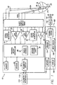
- FIG. 1 An implantable stimulation device 10 in accordance with this invention is shown in FIG. 1 .
- the implantable stimulation device 10 is coupled to a heart 24 by way of leads 32 and 34, the lead 32 having a tip and ring electrodes 18, 19 which are in contact with one of the atria of the heart 24, and the lead 34 having a tip and ring electrode 20, 21 which are in contact with one of the ventricles.
- the lead 32 delivers stimulating pulses from an atrial pulse generator 16 to the atrium, while the lead 34 delivers stimulating pulses from a ventricular pulse generator 22 to the ventricle.
- electrical signals from the atria are delivered by the lead 32 to the input terminal of an atrial sense amplifier 26.
- Electrical signals from the ventricles are delivered through the lead 34 to the input terminal of a ventricular sense amplifier 28.
- Controlling the dual-chamber implantable stimulation device 10 is a control system 30.
- the control system 30 is preferably a microprocessor-based system such as the one disclosed in commonly assigned U.S. Patent No. 4,940,052 of Mann, which is hereby incorporated by reference in its entirety.
- the control system 30 may also be a state logic-based system such as the one disclosed in above-incorporated U.S. Patent No. 4,944,298 of Sholder.
- the control system 30 also includes a real-time clock (not shown) for providing timing for monitoring cardiac events and for timing the application of therapeutic pulses by the pulse generators 16 and 22.
- control system 30 may optionally include circuitry (not shown) for verifying capture and determining the pacing threshold, such for example as disclosed in the above-incorporated U.S. Patent No. 5,417,718 to Kleks et al.; U.S. Patent No. 5,549,652 to McClure et al.; and U.S. Patent No. 4,817,605 to Sholder.
- the implantable stimulation device 10 also includes a memory 14 which is coupled to the control system 30.
- the memory 14 allows certain control parameters used by the control system 30 in controlling the operation of the implantable stimulation device 10 to be telemetrically stored and modified, as required, in order to customize the operation of the implantable stimulation device 10 to suit the needs of a particular patient.
- the pacing capture threshold parameters for the atrial and ventricular pacing pulses are stored in the memory 14.
- data sensed during the operation of the implantable stimulation device 10 may be stored in the memory 14 for later retrieval and analysis.
- the control system 30 receives the output signals from the atrial amplifier 26 and from the ventricular amplifier 28 each time that an atrial event (e.g., a P-wave) or a ventricular event (e.g., an R-wave), respectively, are sensed within the heart 24.
- an atrial event e.g., a P-wave
- a ventricular event e.g., an R-wave
- An A/D converter 42 is shown for providing the intracardiac electrograms (IEGM's)from the leads 32 and 34 to the control system 30. Based on the IEGM's, the controller 30 can apply markers for sensed and paced events, and timing of events, using a marker channel logic unit 38 and a timing and control unit 40, either internal to the control system software/hardware (as shown) or external.
- IEGM's intracardiac electrograms
- the control system 30 also generates an atrial trigger signal which is sent to the atrial pulse generator 16, and a ventricular trigger signal which is sent to the ventricular pulse generator 22. These trigger signals are generated each time that a stimulation pulse is to be generated by one of the pulse generators 16 or 22.
- the atrial stimulation pulse is referred to simply as the "A-pulse,” and the ventricular stimulation pulse is referred to as the "V-pulse".
- the characteristics of these stimulation pulses are determined by the pacing stimulus energy settings that are stored in the memory 14.
- the corresponding atrial amplifier 26 or the ventricular amplifier 28 is typically disabled by way of a blanking signal presented to the appropriate amplifier 26 or 28 from the control system 30.
- This blanking action prevents the amplifiers 26 and 28 from becoming saturated with the relatively large stimulation pulses that are present at their input terminals during pacing pulse delivery.
- This blanking action also prevents residual electrical signals (known as "after-potentials" or polarization) present in the muscle tissue as a result of the implantable stimulation device stimulation from being interpreted as atrial or ventricular events.
- the implantable stimulation device 10 may include an optional sensor 36 connected to the control system 30 for providing additional capture verification by sensing mechanical changes associated with the contraction of the heart 24 and/or for rate modulation.
- a suitable sensor 36 include, but are not limited to, a cardiac wall motion sensor, a cardiac accelerometer, an integral pressure transducer, or an electrical impedance-based ventricular volume sensor.
- the sensor 36 may also be disposed on one or both of the leads 32 and 34, respectively.
- a telemetry circuit 12 is further included in the implantable stimulation device 10 connected to the control system 30.
- the telemetry circuit 12 may be selectively coupled to an external programmer 100 by means of an appropriate communication link 112.
- the communication link 112 may be an electromagnetic telemetry link or a remote communication link such as a pair of modems interconnected via a telecommunications link and equipped with telemetry capabilities.
- the programmer 100 is controlled by a programmer control system 102, which is preferably microprocessor-based.
- a programmer memory 104 is used by the programmer control system 102 for software operation, data processing, and long-term data storage.
- the programmer memory 104 may include random access memory and any type of memory suitable for long-term data storage including a hard disk drive, flash memory, or a rewritable optical disk.
- one or more capture verification assessment and threshold assessment programs may be stored in the programmer memory 102 for selective use by the medical practitioner.
- the programmer 100 is also provided with an display device 108.
- the display device 108 is used to display results of a capture verification test obtained from the implantable stimulation device 10 or performed by the programmer 100.
- An telemetry interface 110 is used to communicate with the implantable stimulation device 10 via the communication link 112.
- the telemetry interface 110 may be a telemetry wand or another type of communication device, for wireless communication with the implantable stimulation device 10.
- the programmer is provided with the capability for detecting and displaying of the patient's surface ECG via surface electrodes and cable, 118, and ECG detection amplifier 116.
- the ECG detection amplifier 116 interacts with the programmer control system 102 such that the surface ECG can be displayed on the display device 108. While the preferred embodiment utilizes the intracardiac electrograms and/or markers from the implantable device 10, the present invention may be adapted to assess electrical signals from the surface ECG for the capture verification assessment function.
- the medical practitioner interacts with the programmer 100 through a user input device 106, which may for example be a keyboard, a pen, or a voice interface. Through the user input device 106, the medical practitioner may also issue commands to the implantable stimulation device 10 when the implantable stimulation device 10 is in communication with the programmer 100.
- An optional printer 114 may be used to print the results of the capture verification and pacing threshold determination test at the medical practitioner's request.
- the operation of the implantable stimulation device 10 is generally controlled by a control program stored in the memory 14 and executed by the control system 30.
- This control program usually consists of multiple integrated program modules, with each module bearing responsibility for controlling one or more functions of the implantable stimulation device 10.
- one program module may control the delivery of stimulating pulses to the heart 24, while another module may control the verification of atrial and/or ventricular capture and pacing threshold determination.
- each program module is a control program dedicated to a specific function or a set of functions of the implantable stimulation device 10.
- the operation of the programmer 100 is generally controlled by a main control program stored in the programmer memory 104 and executed by the programmer control system 102.
- This main control program also consists of multiple integrated program modules that correspond to various features of the programmer 100.
- the control program module dedicated to controlling the capture verification and pacing threshold assessment procedure is described below in connection with FIG. 2 .
- the control program module of FIG. 2 automatically interacts with appropriate control program modules of the implantable stimulation device 10 to conduct one or more portions of the procedure.
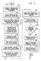
- FIG. 2 a logic flow diagram representing the control program for controlling the capture verification assessment and pacing threshold determination procedure executed by the programmer control system 102 of FIG. 1 in accordance with the present invention is described.
- the programmer control system 102 establishes communication between the implantable stimulation device 10 and the programmer 100.
- the medical practitioner selects one of the chambers of the heart 24 in which capture verification and/or pacing threshold assessment is to be performed. Either the atrial or the ventricular chamber may be selected.
- the medical practitioner may select a particular capture verification assessment and/or threshold assessment function.
- advanced implantable stimulation device and programmer models may be capable of several different capture verification assessment and threshold assessment functions.
- the programmer 100 has superior IEGM analysis capabilities
- Examples of various superior capture verification functions are disclosed in the above-incorporated U.S. Patent No. 5,417,718 (Kleks et al.); U.S. Patent No. 5,549,652 (McClure et al.); and U.S. Patent No. 4,817,605 (Sholder).
- the programmer control system 102 initiates capture verification assessment using a function selected at the step 206.
- the actual capture verification assessment may be performed by the control system 30, by the programmer control system 102, or by both systems 30 and 102 working in conjunction with one another.
- the implantable stimulation device control system 102 composes a capture verification record representative of cardiac events in the atrial and ventricular channels, such as P-waves and R-waves, and implantable stimulation device events, such as A-pulses and V-pulses.
- the cardiac events are identified by the control system 30 from signals received through the atrial and ventricular sense amplifiers 26 and 28, respectively, while the pacing pulses correspond to the trigger signals that are transmitted by the control system 30 to the atrial and ventricular pulse generators 16 and 22, respectively.
- the capture verification record may be based on an IEGM measured by the control system 30.
- the programmer control system 102 may utilize the surface ECG of the patient via the electrodes and cable 118 and the surface ECG input amplifier 116 for the purposes of performing the capture verification assessment function.
- the programmer control system may store a particular surface ECG waveform morphology consistent with ventricular capture in the memory 104 of the programmer. By performing beat by beat comparison of waveform morphology, the programmer will assess the consistency of capture and generate a capture record for display on the programmer display device 108.
- the programmer control system 102 marks A- and/or V- pacing pulses in each of the ventricular and atrial channel portions of the capture verification record with an appropriate PACING PULSE marker.
- an A-pulse may be marked with a letter "A”
- a V-pulse may be marked with a letter "V”.
- Other markers representative of pacing pulses may also be used as a matter of design choice.
- the programmer control system 102 marks verified capture events in the capture verification record with a CAPTURE marker.
- the CAPTURE marker may be a text marker, such as the word "capture” displayed next to a capture event, or it may be a letter "C". Other markers representative of a capture event may also be used as a matter of design choice.
- the programmer control system 102 places a NO CAPTURE marker in each location on the capture verification record where a capture event is expected but does not occur.
- the NO CAPTURE marker may be a text marker, such as the words "no capture” displayed next to a capture event, or it may be the letters "NC”. Other markers representative of the absence of a capture event may also be used as a matter of design choice.
- the programmer control system 102 may also mark the pacing pulses with markers representative of their respective amplitude and duration characteristics. These markers provide the medical practitioner with additional information useful for analysis of the capture verification record.
- the steps 210 through 218 may alternately be performed by the control system 30 of the implantable stimulation device 10 as a matter of design choice without departing from the spirit of the invention.
- the capture verification record may be composed at the implantable stimulation device 10 and then transmitted to the programmer 100 via the communication link 112.
- an exemplary capture verification and threshold assessment record of an atrial capture test is shown.
- the atrial capture threshold is set to 1.8 volts, and thus a 1.6 volt pacing pulse does not capture.
- CAPTURE markers are indicated with "capture”
- the NO CAPTURE marker is indicated with "no capture”.
- the amplitude and duration of pacing pulses is also indicated.
- FIG. 4 an exemplary capture verification and threshold assessment record of a ventricular capture test is shown. In the exemplary record, the ventricular capture threshold is set to 2.2 volts and thus a 2.0 volt pacing pulse does not capture.
- the programmer control system 102 displays the capture verification record to the medical practitioner on the display device 108.
- the capture verification record may also be printed by the printer 114.
- the medical practitioner is prompted by the programmer control system 102 to indicate whether pacing threshold assessment is to be conducted. If the capture verification record shows loss of capture, the medical practitioner will most likely initiate the pacing threshold assessment procedure. If the medical practitioner indicates that pacing capture threshold assessment is to be conducted, the programmer control system 102 proceeds to a step 226. Otherwise, the programmer control system 102 proceeds to a step 224 where the control program ends.
- the pacing capture threshold assessment test may be initiated automatically without input from the medical practitioner.
- the programmer control system 102 performs a pacing capture threshold assessment test to determine an appropriate pacing threshold for the implantable stimulation device 10. Examples of automatic pacing threshold assessment tests are disclosed in the above-incorporated U.S. Patent No. 5,417,718 to Kleks et al.; U.S. Patent No. 5,549,652 to McClure et al.; and U.S. Patent No. 4,817,605 to Sholder.
- the programmer control system 102 composes a pacing threshold assessment record that indicates the atrial and/or ventricular capture thresholds and also indicates the appropriate pacing thresholds for the atrial and/or ventricular channels.
- an automatic threshold assessment function the programmer controls the temporary programming of stimulus capture energy and terminates the threshold assessment function as soon as loss of capture is detected.
- the programmer control system 102 displays the pacing capture threshold assessment record to the medical practitioner on the display device 108.
- the pacing capture threshold assessment record may also be printed by the printer 114.
- the programmer control unit 102 then proceeds to the step 224 where the control program operation ends.
- the medical practitioner is thus presented with complete visual records of automatic capture verification assessment and automatic capture threshold assessment, so that the records may be analyzed and the proper operation of the implantable stimulation device 10 confirmed without subjecting the patient to intensive time consuming procedures such as analysis of the surface ECG during the threshold determination sequence performed by the medical practitioner.
Landscapes
- Health & Medical Sciences (AREA)
- Cardiology (AREA)
- Heart & Thoracic Surgery (AREA)
- Engineering & Computer Science (AREA)
- Biomedical Technology (AREA)
- Nuclear Medicine, Radiotherapy & Molecular Imaging (AREA)
- Radiology & Medical Imaging (AREA)
- Life Sciences & Earth Sciences (AREA)
- Animal Behavior & Ethology (AREA)
- General Health & Medical Sciences (AREA)
- Public Health (AREA)
- Veterinary Medicine (AREA)
- Electrotherapy Devices (AREA)
- Measurement And Recording Of Electrical Phenomena And Electrical Characteristics Of The Living Body (AREA)
Applications Claiming Priority (2)
| Application Number | Priority Date | Filing Date | Title |
|---|---|---|---|
| US764617 | 2001-01-16 | ||
| US09/764,617 US20020095190A1 (en) | 2001-01-16 | 2001-01-16 | System and method for automating capture verification assessment and pacing threshold assessment using a programmer |
Publications (3)
| Publication Number | Publication Date |
|---|---|
| EP1222942A2 true EP1222942A2 (de) | 2002-07-17 |
| EP1222942A3 EP1222942A3 (de) | 2004-01-21 |
| EP1222942B1 EP1222942B1 (de) | 2006-06-21 |
Family
ID=25071258
Family Applications (1)
| Application Number | Title | Priority Date | Filing Date |
|---|---|---|---|
| EP02250262A Expired - Lifetime EP1222942B1 (de) | 2001-01-16 | 2002-01-15 | Vorrichtung zur Festsetzung des Einfangens und des Schwellwertes mittels einer Programmiereinrichtung |
Country Status (3)
| Country | Link |
|---|---|
| US (1) | US20020095190A1 (de) |
| EP (1) | EP1222942B1 (de) |
| DE (1) | DE60212467T2 (de) |
Cited By (4)
| Publication number | Priority date | Publication date | Assignee | Title |
|---|---|---|---|---|
| WO2004112898A3 (en) * | 2003-06-17 | 2005-03-24 | Medtronic Inc | Cardiac pacing apparatus and method for continuous capture management |
| WO2006104846A1 (en) * | 2005-03-31 | 2006-10-05 | Medtronic, Inc. | System and method for remote pacing threshold assessment |
| WO2008134620A1 (en) * | 2007-04-30 | 2008-11-06 | Medtronic, Inc. | Mechanical ventricular pacing non-capture detection for a refractory period stimulation (rps) pacing therapy using at least one lead-based accelerometer |
| US7587243B1 (en) | 2006-05-08 | 2009-09-08 | Pacesetter, Inc. | System and method for verifying capture and/or event sensing during manual threshold evaluations of an implantable cardiac stimulation device |
Families Citing this family (7)
| Publication number | Priority date | Publication date | Assignee | Title |
|---|---|---|---|---|
| US6353761B1 (en) * | 1999-08-20 | 2002-03-05 | Cardiac Pacemakers, Inc. | Cardiac rhythm management system with user interface for threshold test |
| US7076301B1 (en) * | 2002-12-20 | 2006-07-11 | Pacesetter | Implantable cardiac stimulation device that minimizes parasitic muscle stimulation and method |
| US9037239B2 (en) * | 2007-08-07 | 2015-05-19 | Cardiac Pacemakers, Inc. | Method and apparatus to perform electrode combination selection |
| US8755902B2 (en) * | 2009-12-30 | 2014-06-17 | ResQCor | Systems and methods for placing electronic devices into “cautery-safe” mode |
| US8639323B2 (en) * | 2010-11-01 | 2014-01-28 | Medtronic, Inc. | System and apparatus to monitor biopacemaker maturation |
| US10004907B2 (en) | 2014-02-21 | 2018-06-26 | Pacesetter, Inc. | Automatic capture verification within leadless implantable medical devices |
| WO2018081237A1 (en) * | 2016-10-27 | 2018-05-03 | Cardiac Pacemakers, Inc. | Use of a separate device in managing the pace pulse energy of a cardiac pacemaker |
Citations (3)
| Publication number | Priority date | Publication date | Assignee | Title |
|---|---|---|---|---|
| US4817605A (en) | 1984-10-19 | 1989-04-04 | Siemens-Pacesetter, Inc. | Pacemaker system and method for measuring and monitoring cardiac activity and for determining and maintaining capture |
| US5417718A (en) | 1992-11-23 | 1995-05-23 | Pacesetter, Inc. | System for maintaining capture in an implantable pulse generator |
| US5549652A (en) | 1993-11-15 | 1996-08-27 | Pacesetter, Inc. | Cardiac wall motion-based automatic capture verification system and method |
Family Cites Families (5)
| Publication number | Priority date | Publication date | Assignee | Title |
|---|---|---|---|---|
| US4055189A (en) * | 1975-05-19 | 1977-10-25 | Medalert Corporation | Condition monitoring pacer |
| US5304209A (en) * | 1991-09-24 | 1994-04-19 | Angeion Corporation | Remote-control temporary pacemaker |
| US5549654A (en) * | 1994-04-15 | 1996-08-27 | Medtronic, Inc. | Interactive interpretation of event markers in body-implantable medical device |
| US5702427A (en) * | 1996-03-28 | 1997-12-30 | Medtronic, Inc. | Verification of capture using pressure waves transmitted through a pacing lead |
| US5873898A (en) * | 1997-04-29 | 1999-02-23 | Medtronic, Inc. | Microprocessor capture detection circuit and method |
-
2001
- 2001-01-16 US US09/764,617 patent/US20020095190A1/en not_active Abandoned
-
2002
- 2002-01-15 DE DE60212467T patent/DE60212467T2/de not_active Expired - Lifetime
- 2002-01-15 EP EP02250262A patent/EP1222942B1/de not_active Expired - Lifetime
Patent Citations (3)
| Publication number | Priority date | Publication date | Assignee | Title |
|---|---|---|---|---|
| US4817605A (en) | 1984-10-19 | 1989-04-04 | Siemens-Pacesetter, Inc. | Pacemaker system and method for measuring and monitoring cardiac activity and for determining and maintaining capture |
| US5417718A (en) | 1992-11-23 | 1995-05-23 | Pacesetter, Inc. | System for maintaining capture in an implantable pulse generator |
| US5549652A (en) | 1993-11-15 | 1996-08-27 | Pacesetter, Inc. | Cardiac wall motion-based automatic capture verification system and method |
Cited By (7)
| Publication number | Priority date | Publication date | Assignee | Title |
|---|---|---|---|---|
| WO2004112898A3 (en) * | 2003-06-17 | 2005-03-24 | Medtronic Inc | Cardiac pacing apparatus and method for continuous capture management |
| US7831303B2 (en) | 2003-06-17 | 2010-11-09 | Medtronic, Inc. | Cardiac pacing apparatus and method for continuous capture management |
| WO2006104846A1 (en) * | 2005-03-31 | 2006-10-05 | Medtronic, Inc. | System and method for remote pacing threshold assessment |
| US7738960B2 (en) | 2005-03-31 | 2010-06-15 | Medtronic, Inc. | System and method for remote pacing threshold assessment |
| US7587243B1 (en) | 2006-05-08 | 2009-09-08 | Pacesetter, Inc. | System and method for verifying capture and/or event sensing during manual threshold evaluations of an implantable cardiac stimulation device |
| WO2008134620A1 (en) * | 2007-04-30 | 2008-11-06 | Medtronic, Inc. | Mechanical ventricular pacing non-capture detection for a refractory period stimulation (rps) pacing therapy using at least one lead-based accelerometer |
| US7787942B2 (en) | 2007-04-30 | 2010-08-31 | Medtronic, Inc. | Mechanical ventricular pacing non-capture detection for a refractory period stimulation (RPS) pacing therapy using at least one lead-based accelerometer |
Also Published As
| Publication number | Publication date |
|---|---|
| EP1222942B1 (de) | 2006-06-21 |
| DE60212467D1 (de) | 2006-08-03 |
| US20020095190A1 (en) | 2002-07-18 |
| DE60212467T2 (de) | 2007-01-04 |
| EP1222942A3 (de) | 2004-01-21 |
Similar Documents
| Publication | Publication Date | Title |
|---|---|---|
| US6345201B1 (en) | System and method for ventricular capture using far-field evoked response | |
| US6324427B1 (en) | Implantable cardiac stimulation device having T-wave discrimination of fusion events during autocapture/autothreshold assessment | |
| US5421830A (en) | Programming system having means for recording and analyzing a patient's cardiac signal | |
| US6101416A (en) | System and method for atrial autocapture in single-chamber pacemaker modes using far-field detection | |
| US5605158A (en) | Apparatus for annotating physiological waveforms | |
| USRE42836E1 (en) | Method for assessing cardiac functional status | |
| US8886300B2 (en) | Methods and systems for selecting capture verification modes | |
| US7096065B2 (en) | Cardiac rhythm management system with user interface for threshold test | |
| JP5674737B2 (ja) | 逆行管理を実行する心臓システム | |
| US6408210B1 (en) | System and method for automatic atrial capture detection and atrial pacing threshold determination | |
| US6389316B1 (en) | System and method for automatic atrial capture detection and atrial pacing threshold determination | |
| US6295471B1 (en) | System and method for automatic atrial capture detection and atrial pacing threshold determination | |
| CN109219468B (zh) | 用于多部位刺激的方法和系统 | |
| EP0922468B1 (de) | Automatische Feststellung des Ansprechens des Herzens wärend einer nichtinvasiven Herzstimulation | |
| EP1222942B1 (de) | Vorrichtung zur Festsetzung des Einfangens und des Schwellwertes mittels einer Programmiereinrichtung | |
| US11779771B2 (en) | Implantable medical device for stimulating a human or animal heart employing an evaluation of signals between a His electrode and a further electrode | |
| US8750975B2 (en) | Implantable heart monitoring device and method | |
| US20100099994A1 (en) | Implantable heart analyzing device, system and method | |
| US7587243B1 (en) | System and method for verifying capture and/or event sensing during manual threshold evaluations of an implantable cardiac stimulation device |
Legal Events
| Date | Code | Title | Description |
|---|---|---|---|
| PUAI | Public reference made under article 153(3) epc to a published international application that has entered the european phase |
Free format text: ORIGINAL CODE: 0009012 |
|
| AK | Designated contracting states |
Kind code of ref document: A2 Designated state(s): AT BE CH CY DE DK ES FI FR GB GR IE IT LI LU MC NL PT SE TR |
|
| AX | Request for extension of the european patent |
Free format text: AL;LT;LV;MK;RO;SI |
|
| PUAL | Search report despatched |
Free format text: ORIGINAL CODE: 0009013 |
|
| AK | Designated contracting states |
Kind code of ref document: A3 Designated state(s): AT BE CH CY DE DK ES FI FR GB GR IE IT LI LU MC NL PT SE TR |
|
| AX | Request for extension of the european patent |
Extension state: AL LT LV MK RO SI |
|
| 17P | Request for examination filed |
Effective date: 20040629 |
|
| 17Q | First examination report despatched |
Effective date: 20040810 |
|
| AKX | Designation fees paid |
Designated state(s): CH DE FR IE IT LI |
|
| GRAP | Despatch of communication of intention to grant a patent |
Free format text: ORIGINAL CODE: EPIDOSNIGR1 |
|
| RTI1 | Title (correction) |
Free format text: SYSTEM FOR AUTOMATING CAPTURE VERIFICATION ASSESSMENT AND PACING THRESHOLD ASSESSMENT USING A PROGRAMMER |
|
| GRAS | Grant fee paid |
Free format text: ORIGINAL CODE: EPIDOSNIGR3 |
|
| GRAA | (expected) grant |
Free format text: ORIGINAL CODE: 0009210 |
|
| AK | Designated contracting states |
Kind code of ref document: B1 Designated state(s): CH DE FR IE IT LI |
|
| PG25 | Lapsed in a contracting state [announced via postgrant information from national office to epo] |
Ref country code: IT Free format text: LAPSE BECAUSE OF FAILURE TO SUBMIT A TRANSLATION OF THE DESCRIPTION OR TO PAY THE FEE WITHIN THE PRESCRIBED TIME-LIMIT;WARNING: LAPSES OF ITALIAN PATENTS WITH EFFECTIVE DATE BEFORE 2007 MAY HAVE OCCURRED AT ANY TIME BEFORE 2007. THE CORRECT EFFECTIVE DATE MAY BE DIFFERENT FROM THE ONE RECORDED. Effective date: 20060621 |
|
| REG | Reference to a national code |
Ref country code: CH Ref legal event code: EP |
|
| REG | Reference to a national code |
Ref country code: IE Ref legal event code: FG4D |
|
| REF | Corresponds to: |
Ref document number: 60212467 Country of ref document: DE Date of ref document: 20060803 Kind code of ref document: P |
|
| REG | Reference to a national code |
Ref country code: CH Ref legal event code: NV Representative=s name: KIRKER & CIE SA |
|
| PG25 | Lapsed in a contracting state [announced via postgrant information from national office to epo] |
Ref country code: IE Free format text: LAPSE BECAUSE OF NON-PAYMENT OF DUE FEES Effective date: 20070115 |
|
| ET | Fr: translation filed | ||
| PLBE | No opposition filed within time limit |
Free format text: ORIGINAL CODE: 0009261 |
|
| STAA | Information on the status of an ep patent application or granted ep patent |
Free format text: STATUS: NO OPPOSITION FILED WITHIN TIME LIMIT |
|
| 26N | No opposition filed |
Effective date: 20070322 |
|
| PGFP | Annual fee paid to national office [announced via postgrant information from national office to epo] |
Ref country code: FR Payment date: 20100303 Year of fee payment: 9 Ref country code: IT Payment date: 20100225 Year of fee payment: 9 |
|
| REG | Reference to a national code |
Ref country code: FR Ref legal event code: ST Effective date: 20110930 |
|
| PG25 | Lapsed in a contracting state [announced via postgrant information from national office to epo] |
Ref country code: FR Free format text: LAPSE BECAUSE OF NON-PAYMENT OF DUE FEES Effective date: 20110131 |
|
| PG25 | Lapsed in a contracting state [announced via postgrant information from national office to epo] |
Ref country code: IT Free format text: LAPSE BECAUSE OF NON-PAYMENT OF DUE FEES Effective date: 20110115 |
|
| PGFP | Annual fee paid to national office [announced via postgrant information from national office to epo] |
Ref country code: CH Payment date: 20140129 Year of fee payment: 13 |
|
| REG | Reference to a national code |
Ref country code: CH Ref legal event code: PL |
|
| PG25 | Lapsed in a contracting state [announced via postgrant information from national office to epo] |
Ref country code: LI Free format text: LAPSE BECAUSE OF NON-PAYMENT OF DUE FEES Effective date: 20150131 Ref country code: CH Free format text: LAPSE BECAUSE OF NON-PAYMENT OF DUE FEES Effective date: 20150131 |
|
| PGFP | Annual fee paid to national office [announced via postgrant information from national office to epo] |
Ref country code: DE Payment date: 20181219 Year of fee payment: 18 |
|
| REG | Reference to a national code |
Ref country code: DE Ref legal event code: R119 Ref document number: 60212467 Country of ref document: DE |
|
| PG25 | Lapsed in a contracting state [announced via postgrant information from national office to epo] |
Ref country code: DE Free format text: LAPSE BECAUSE OF NON-PAYMENT OF DUE FEES Effective date: 20200801 |