EP1222967A2 - Sprühverfahren und Sprühvorrichtung für Beschichtungsflüssigkeit - Google Patents
Sprühverfahren und Sprühvorrichtung für Beschichtungsflüssigkeit Download PDFInfo
- Publication number
- EP1222967A2 EP1222967A2 EP02000318A EP02000318A EP1222967A2 EP 1222967 A2 EP1222967 A2 EP 1222967A2 EP 02000318 A EP02000318 A EP 02000318A EP 02000318 A EP02000318 A EP 02000318A EP 1222967 A2 EP1222967 A2 EP 1222967A2
- Authority
- EP
- European Patent Office
- Prior art keywords
- spray
- liquid
- jet
- additional liquid
- spray jet
- Prior art date
- Legal status (The legal status is an assumption and is not a legal conclusion. Google has not performed a legal analysis and makes no representation as to the accuracy of the status listed.)
- Granted
Links
- 239000007788 liquid Substances 0.000 title claims abstract description 140
- 239000011248 coating agent Substances 0.000 title claims abstract description 58
- 238000000576 coating method Methods 0.000 title claims abstract description 58
- 238000005507 spraying Methods 0.000 title claims abstract description 25
- 238000000034 method Methods 0.000 title claims abstract 3
- 239000007921 spray Substances 0.000 claims abstract description 97
- 230000002093 peripheral effect Effects 0.000 claims description 23
- 239000002826 coolant Substances 0.000 claims description 21
- 238000001816 cooling Methods 0.000 claims description 14
- 230000009969 flowable effect Effects 0.000 claims description 3
- 239000000654 additive Substances 0.000 claims 1
- 230000000996 additive effect Effects 0.000 claims 1
- 238000000889 atomisation Methods 0.000 abstract description 2
- 239000002245 particle Substances 0.000 description 6
- 239000002904 solvent Substances 0.000 description 5
- 239000007789 gas Substances 0.000 description 4
- 238000001035 drying Methods 0.000 description 2
- 230000005686 electrostatic field Effects 0.000 description 2
- 239000000126 substance Substances 0.000 description 2
- 239000003039 volatile agent Substances 0.000 description 2
- XLYOFNOQVPJJNP-UHFFFAOYSA-N water Substances O XLYOFNOQVPJJNP-UHFFFAOYSA-N 0.000 description 2
- 230000006978 adaptation Effects 0.000 description 1
- 238000004140 cleaning Methods 0.000 description 1
- 239000000112 cooling gas Substances 0.000 description 1
- 238000001704 evaporation Methods 0.000 description 1
- 230000008020 evaporation Effects 0.000 description 1
- 239000012530 fluid Substances 0.000 description 1
- 239000003292 glue Substances 0.000 description 1
- 239000004615 ingredient Substances 0.000 description 1
- 239000004922 lacquer Substances 0.000 description 1
- 239000002184 metal Substances 0.000 description 1
- 239000003595 mist Substances 0.000 description 1
- 239000000615 nonconductor Substances 0.000 description 1
- 239000003973 paint Substances 0.000 description 1
- 238000007493 shaping process Methods 0.000 description 1
- 238000011144 upstream manufacturing Methods 0.000 description 1
Images

Classifications
-
- B—PERFORMING OPERATIONS; TRANSPORTING
- B05—SPRAYING OR ATOMISING IN GENERAL; APPLYING FLUENT MATERIALS TO SURFACES, IN GENERAL
- B05B—SPRAYING APPARATUS; ATOMISING APPARATUS; NOZZLES
- B05B5/00—Electrostatic spraying apparatus; Spraying apparatus with means for charging the spray electrically; Apparatus for spraying liquids or other fluent materials by other electric means
- B05B5/001—Electrostatic spraying apparatus; Spraying apparatus with means for charging the spray electrically; Apparatus for spraying liquids or other fluent materials by other electric means incorporating means for heating or cooling, e.g. the material to be sprayed
-
- B—PERFORMING OPERATIONS; TRANSPORTING
- B05—SPRAYING OR ATOMISING IN GENERAL; APPLYING FLUENT MATERIALS TO SURFACES, IN GENERAL
- B05B—SPRAYING APPARATUS; ATOMISING APPARATUS; NOZZLES
- B05B15/00—Details of spraying plant or spraying apparatus not otherwise provided for; Accessories
- B05B15/50—Arrangements for cleaning; Arrangements for preventing deposits, drying-out or blockage; Arrangements for detecting improper discharge caused by the presence of foreign matter
- B05B15/55—Arrangements for cleaning; Arrangements for preventing deposits, drying-out or blockage; Arrangements for detecting improper discharge caused by the presence of foreign matter using cleaning fluids
-
- B—PERFORMING OPERATIONS; TRANSPORTING
- B05—SPRAYING OR ATOMISING IN GENERAL; APPLYING FLUENT MATERIALS TO SURFACES, IN GENERAL
- B05B—SPRAYING APPARATUS; ATOMISING APPARATUS; NOZZLES
- B05B5/00—Electrostatic spraying apparatus; Spraying apparatus with means for charging the spray electrically; Apparatus for spraying liquids or other fluent materials by other electric means
- B05B5/025—Discharge apparatus, e.g. electrostatic spray guns
- B05B5/04—Discharge apparatus, e.g. electrostatic spray guns characterised by having rotary outlet or deflecting elements, i.e. spraying being also effected by centrifugal forces
-
- B—PERFORMING OPERATIONS; TRANSPORTING
- B05—SPRAYING OR ATOMISING IN GENERAL; APPLYING FLUENT MATERIALS TO SURFACES, IN GENERAL
- B05B—SPRAYING APPARATUS; ATOMISING APPARATUS; NOZZLES
- B05B5/00—Electrostatic spraying apparatus; Spraying apparatus with means for charging the spray electrically; Apparatus for spraying liquids or other fluent materials by other electric means
- B05B5/025—Discharge apparatus, e.g. electrostatic spray guns
- B05B5/04—Discharge apparatus, e.g. electrostatic spray guns characterised by having rotary outlet or deflecting elements, i.e. spraying being also effected by centrifugal forces
- B05B5/0426—Means for supplying shaping gas
Definitions
- the invention relates to a spraying method and a spraying device for Coating liquid according to the preamble of claim 1 and of Claim 6.
- Spray devices with a rotary atomizer body in the form of a rotating bell for atomizing and spraying coating liquid an object to be coated are from US 4,275,838, US 4,505,430, DE 30 00 002 A1 and DE 35 09 874 A1 known. From this it is also known that Rotary atomizer and / or the spray coating liquid on electrical high voltage potential, which is a negative or positive High voltage potential can be connected. The high voltage lies usually in the range between 4,000 V and 140,000 V.
- a high-voltage spray device with a non-rotating spray nozzle is from US 3,731,145 known.
- Rotary atomizer bodies usually have a bell shape or one Disc shape and can rotate at up to 60,000 rpm.
- the coating liquid can be solvent-based or be water-dilutable liquid, in particular paint, colored lacquer, or Clearcoat.
- the different types of coating liquids have different ones Viscosities and different drying speeds.
- the Liquid particles in the spray jet have different shapes, sizes and Flight characteristics on the way from the liquid atomizer to the coating object.
- the high voltage creates an electrostatic field between the Spray device and an electrically conductive, grounded, to be coated Object. This reduces scatter losses in the spray jet and makes them faster Coating speeds and better coating qualities.
- the adherence of the liquid particles to the object to be coated are depending on the type of coating liquid and the electrostatic Field.
- the object of the invention is to be achieved in simple and inexpensive manner Way of coating efficiency and coating quality influence.
- the invention relates to a spraying method for coating liquid, in which from a spray device through a liquid atomizer Form of a non-rotating nozzle or in the form of a rotating Rotating atomizer body coating liquid on a to be coated Object is sprayed, characterized in that in the spray jet Coating liquid an additional liquid is metered and thus supplied the microclimate in the spray jet is influenced.
- the invention further relates to a spray device for coating liquid, containing a liquid atomizer in the form of a non-rotating nozzle or in the form of a rotating rotary atomizer body for spraying the Coating liquid on an object to be coated, thereby characterized in that an additional liquid supply device for metered supply of additional liquid is provided in the spray jet of the coating liquid is.
- This metered supply of additional liquid on or in the spray jet Coating liquid can affect the "microclimate" in the spray jet and thus also the Coating efficiency and the coating quality affected and the can be adapted to different conditions in practice.
- the "microclimate” contains in particular the moisture content in the spray jet and the ratio of volatiles to non-volatiles Ingredients in the spray jet.
- the color particles of low viscosity Coating liquids by adding additional liquid be “diluted” and thereby better atomized in the spray as well are better charged electrostatically.
- additional liquid it has also affect the electrical current generated by the spray from the Spray device flows to the grounded object to be coated.
- the Additional liquid also influences the fluidity of the liquid particles Coating liquid on the object to be coated.
- Cooled coating liquid in the spray device before its atomization e.g. B. in the liquid atomizer body or upstream thereof. This will make the Viscosity and the rate of evaporation (drying out) of the Coating liquid reduced. This also makes the "microclimate” influenceable and the coating efficiency and the coating quality improvable.
- water for water-dilutable is expediently Coating liquids or solvents for solvents Coating liquids used.
- the additional liquid is preferably in the initial region of the spray jet fed before its full diameter by the Additional liquid supply device in the initial area of the spray jet is judged.
- the Characteristics of this spray different types of objects and can be adapted to different types of coating liquids.
- the object surface to be coated is vertical or horizontal.
- the Spray jet axis around or partially extending slot nozzle or one or a plurality of round or arranged around the spray jet axis angular openings, in particular nozzle openings, on the spray device be provided.
- the spray device can have one or more of the following compressed air supplies: shaping air, which on the spray is applied, for example surrounding it in a bell shape and with flows with him to shape him; Bearing air on which the Rotary atomizer body and / or a turbine driving it is mounted; Turbine air for driving the turbine; Break air to Braking the turbine and the rotary atomizer body.
- shaping air which on the spray is applied, for example surrounding it in a bell shape and with flows with him to shape him
- Turbine air for driving the turbine
- Break air to Braking the turbine and the rotary atomizer body.
- One or more Types of this air can be cooled according to the invention and as Cooling medium for cooling the coating liquid in the spray device be used.
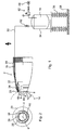
- the spray device 2 shown in the drawings according to the invention for Coating liquid contains a liquid atomizer in the form of a an air turbine (not shown) drivable rotary atomizer body 4.
- This is preferably an atomizer bell or an atomizer disc rotates about an axis of rotation 6, an outer peripheral surface 8 and a front End face 10 has.
- the end face 10 has a bell shape (or plate shape). about the rotating end face 10 flows radially from the inside to the outside Coating liquid flowing from the bell rim 12, i.e. the Outer peripheral edge of the end face 10, by the centrifugal force of the rotating Rotary atomizer body 4 in the form of a forward spray 14 is delivered.
- the rotary atomizer body 4 is preferably at high electrical voltage to create a high voltage field between it and the coating object connected.
- a supply device 16 for the metered supply of additional liquid 18 and / or in the spray jet 14 contains itself (on or) through a housing 20 of the spray device extending auxiliary liquid line 22 to an on (on or outlet body 24 arranged in the housing 20.
- the outlet body 24 has at least one, for example three outlet openings 26 through which the Additional liquid 18 flows forward into the spray jet 14.
- the additional liquid line 22 is at the rear end of the housing 20 through a external auxiliary liquid supply line 30, which has a controllable valve 32 contains, connected to a supply container 34, in which the Additional liquid 18 is stored.
- the additional liquid 18 can be the same electrical high voltage can be connected like the rotary atomizer body 4 and therefore stands on electrical insulators 36 on a base 38.
- FIG. 1 shows another embodiment in which Supply container 34 through a gas pressure control device 42 a gas pressure is generated, preferably compressed air from a compressed air source 34, through which at open valve 32 additional liquid 18 from the supply container 34 to Outlet body 24 and is pressed into the spray 14 by this.
- the additional liquid 18 is preferably water if the Coating liquid of the spray jet 14 is a water-soluble substance.
- the additional liquid is preferably a solvent if the Coating liquid of the spray jet 14 is a solvent-containing substance.
- the supply of additional liquid in the spray jet 14 enables one Change and adaptation of the spray mist consistency or the microclimate of the Spray jet 14 for various coating liquids.
- the device for supplying coating liquid to the Rotary atomizer body 4 is not shown since it is from the prior art is known, for example from US 4,275,838 and US 4,505,430.
- the at least one outlet opening 26 for additional liquid 18 can be one have a circular or angular cross section or a slot shape, for example be a slit nozzle that extends around part or all of it Device scope extends around the axis of rotation 6.
- the additional liquid 18 is metered into the spray jet 14. So that can the microclimate (moisture content, temperature, viscosity) in the liquid jet 14 depending on operating conditions such as type of Coating liquid and type of object to be coated are affected during coating efficiency and coating quality be improved.
- microclimate moisture content, temperature, viscosity
- the additional liquid 18 becomes the initial area of the liquid jet 14 supplied before the liquid jet 14 reaches its largest diameter Has.
- the additional liquid 18 is preferably directly at the front end of the Liquid atomizer 4 fed to the spray jet 14.
- the outlet opening or openings 26 can be used as nozzle openings be formed, from which the additional liquid 18 as a bundled jet or emerges as an atomizing jet.
- the additional liquid 18 can flow from the at least one outlet opening 26 either be directed directly into the spray 14 or such that at least part or all of the additional liquid 18 from the Outlet openings 26 on the outer peripheral end portion 46 of the Rotary atomizer body 4 arrives and from this Outer peripheral end portion 46 is directed into the spray 14.
- the Feed device 16 for the additional liquid 18, in particular the Outlet openings 26 and the supply pressure of the additional liquid 18 can either be designed such that the additional liquid 18 as Liquid jet emerges from the outlet openings 26, or formed in such a way be that the additional liquid only drops from the outlet openings 26th emerges and on the outer peripheral end portion 46 of Rotary atomizer body 4 drips.
- the rotation of the rotary atomizer body 4 generates a centrifugal force through which the additional liquid 18 from its Outer peripheral end portion 46 into the spray 14 of the coating liquid is thrown out.
- the spraying of at least part of the additional liquid 18 on the Outer peripheral end portion 46 of the rotary atomizer body 4 has the additional advantage that there is none on this outer peripheral end section 46 Can deposit particles of the coating liquid and harden there. Consequently this outer peripheral end portion 46 is kept clean.
- a cooling device 50 for cooling one of the coating liquid on its way to the spray jet 14 contacted device part, in the present embodiment of the Rotary atomizer body 4, by means of a flowable, cooled medium provided during the spray coating operation to the cold of the cooled cooling medium through the cold-conductive device part 4 transfer the spray coating fluid before it is sprayed.
- the cooling medium 52 is behind the Outer peripheral end portion 46 directed to the outer peripheral surface 54 and the Cooling of the coolant 52 is caused by the rotary atomizer body 4, which is cold conductive, for example made of metal, on the coating liquid transferred, which flows through it and then as a spray 14 is sprayed.
- the cooling device 50 guides the coolant 52, preferably cooled compressed gas, in particular cooled compressed air, in a cooling medium line 56 to one Coolant outlet 58, which on the outer peripheral surface 54 of the Rotary atomizer body 4 is directed.
- the cold of the cooling medium runs through the rotary atomizer body 4 through to its end face 10, over which the coating liquid when spun off by the rotating Rotary atomizer body 4 flows and from the outer edge of the body in the form of Spray jet 14 is thrown off.
- a cooling device 60 for cooling the cooling medium 52 is preferably immediate arranged on the spray device 2 or integrated into this. This results in short paths for the cooling medium 52.
- the cooling medium 52 preferably a Compressed gas, for example compressed air from a compressed air source 64, becomes the cooling device 60 metered in via a metering device 66 (e.g. valve arrangement), from cooled the cooling device 60 and then through the cooling medium line 56 to the Rotation atomizer body 4 directed.
- the cooling device 60 can be used to cool the Cooling medium 52 preferably contain a so-called cooling gas cartridge.
- the cooling of the rotary atomizer body by the cooling medium 52 has the Another advantage that it is the rotary atomizer body in its Outer peripheral end portion 46 cools. On this outer peripheral end portion 46 sometimes migrate backward from the spray 14 Be Anlagenungs remplikeitsteilchen. Due to the reduced temperature, this can Coating liquid particles on the outer peripheral end portion 46 only harden and glue at a much lower speed than with a warmer temperature. This means that less cleaning work is required.
Landscapes
- Application Of Or Painting With Fluid Materials (AREA)
- Electrostatic Spraying Apparatus (AREA)
- Nozzles (AREA)
Abstract
Description
- Fig. 1
- schematisch unten eine Seitenansicht und oben einen Längsschnitt einer Sprühvorrichtung nach der Erfindung,
- Fig. 2
- schematisch eine Frontansicht von links der Sprühvorrichtung von Fig. 1,
- Fig. 3
- schematisch unten eine Seitenansicht und oben einen Längsschnitt einer weiteren Ausführungsform einer Sprühvorrichtung nach der Erfindung.
Claims (20)
- Sprüverfahren für Beschichtungsflüssigkeit, bei welchem von einer Sprühvorrichtung (2) durch einen Flüssigkeitszerstäuber (4) in Form einer nicht-rotierenden Düse oder in Form eines rotierenden Rotationszerstäuberkörpers Beschichtungsflüssigkeit auf ein zu beschichtendes Objekt gesprüht wird,
dadurch gekennzeichnet, daß in den Sprühstrahl (14) der Beschichtungsflüssigkeit eine Zusatzflüssigkeit (18) dosiert zugeführt wird und damit das Mikroklima im Sprühstrahl beeinflußt wird. - Sprühverfahren nach Anspruch 1,
dadurch gekennzeichnet, daß die Zusatzflüssigkeit (18) dem Anfangsbereich des Sprühstrahles (14) zugeführt wird, bevor er seinen vollen Durchmesser erreicht hat. - Sprühverfahren nach Anspruch 2,
dadurch gekennzeichnet, daß die Zusatzflüssigkeit (18) am vorderen Ende des Flüssigkeitszerstäubers (4) oder kurz stromabwärts davon dem Sprühstrahl zugeführt wird. - Sprühverfahren nach einem der vorhergehenden Ansprüche,
dadurch gekennzeichnet, daß die Zusatzflüssigkeit (18) um mindestens einen Teilumfang des Sprühstrahles (14) herum verteilt dem Sprühstrahl zugeführt wird. - Sprühverfahren nach einem der vorhergehenden Ansprüche,
dadurch gekennzeichnet, daß mindestens ein Teil der Zusatzflüssigkeit (18) auf einen vorderen Außenumfangsendabschnitt (46) des Flüssigkeitszerstäubers (4) aufgebracht wird und dann durch diesen in den Sprühstrahl (14) geleitet wird. - Sprühverfahren nach einem der vorhergehenden Ansprüche,
dadurch gekennzeichnet, daß die Zusatzflüssigkeit (18) durch mindestens eine Düsenöffnung (26), die am vorderen Endabschnitt der Sprühvorrichtung (2) gebildet ist, in Form eines ununterbrochenen Strahles dem Sprühstrahl (14) zugeführt wird. - Sprühverfahren nach einem der vorhergehenden Ansprüche,
dadurch gekennzeichnet, daß der Flüssigkeitszerstäuber (4) ein Rotationszerstäuberkörper ist und daß die Zusatzflüssigkeit (18) auf den Außenumfangsendabschnitt (46) des Rotationszerstäuberköpers (4) aufgetropft wird und dann von diesem Außenumfangsendabschnitt (46) durch dessen Rotationsfliekräfte in den Sprühstrahl (14) abgeschleudert wird. - Sprühverfahren nach einem der vorhergehenden Ansprüche,
dadurch gekennezeichnet,
daß ein Vorrichtungsteil (4), welcher von der Beschichtungsflüssigkeit auf ihrem Weg zum Sprühstrahl (14) in der Sprühvorrichtung kontaktiert wird, mittels eines strömungsfähigen gekühlten Kühlmediums (52) gekühlt wird und daß diese Kälte des Kühlmediums durch die Kälteleitfähigkeit des Vorrichtungsteiles (4) auf die Sprühbeschichtungsflüssigkeit übertragen wird. - Sprühvorrichtung für Beschichtungsflüssigkeit, enthaltend einen Flüssigkeitszerstäuber (4) in Form einer nicht-rotierenden Düse oder in Form eines rotierenden Rotationszerstäuberkörper zum Sprühen der Beschichtungsflüssigkeit auf ein zu beschichtendes Objekt,
dadurch gekennzeichnet, daß eine Zusatzflüssigkeits-Zufuhreinrichtung (16) mit mindestens einem Auslaß (26) zur dosierten Zufuhr von Zusatzflüssigkeit (18) in den Sprühstrahl (14) der Beschichtungsflüssigkeit vorgesehen ist. - Sprühvorrichtung nach Anspruch 9,
dadurch gekennzeichnet, daß die Zusatzflüssigkeits-Zufuhreinrichtung (16) zur Zufuhr der Zusatzflüssigkeit (18) in den Anfangsbereich des Sprühstrahles (14) ausgebildet ist, bevor dieser seinen größten Durchmesser erreicht. - Sprühvorrichtung nach Anspruch 9 oder 10,
dadurch gekennzeichnet, daß die Zusatzflüssigkeits-Zufuhreinrichtung (16) ausgebildet ist zur Zufuhr der Zusatzflüssigkeit (18) in den Sprühstrahl (14) am vorderen Ende des Flüssigkeitszerstäubers (4). - Sprühvorrichtung nach einem der Ansprüche 9 bis 11,
dadurch gekennzeichnet, daß die Zusatzflüssigkeits-Zufuhreinrichtung (16) ausgebildet ist zur Zufuhr der Zusatzflüssigkeit (18) in den Sprühstrahl (14) um den Sprühstrahl herum verteilt. - Sprühvorrichtung nach einem der Ansprüche 9 bis 12,
dadurch gekennzeichnet, daß die Zusatzflüssigkeits-Zufuhreinrichtung (16) ausgebildet ist, um mindestens einen Teil der Zusatzflüssigeit (18) auf einen vorderen Außenumfangsendabschnitt (46) des Flüssigkeitszerstäuber (4) aufzubringen und dann von diesem Außenumfangsendabschnitt (46) in den Sprühstrahl (14) zu leiten. - Sprühvorrichtung nach einem der Ansprüche 9 bis 13,
dadurch gekennzeichnet, daß der mindestens eine Auslaß (26) für Zusatzflüssigkeit (18) am vorderen Endabschnitt der Sprühvorrichtung (2) gebildet ist. - Sprühvorrichtung nach Anspruch 14,
dadurch gekennzeichnet, daß der Flüssigkeitszerstäuber (4) ein Rotationszerstäuberkörper ist und
daß die Zusatzflüssigkeits-Zufuhreinrichtung (16) ausgebildet ist zum Auftropfen der Zusatzsflüssigkeit (18) auf den vorderen Außenumfangsendabschnitt (46) des Rotationszerstäuberkörpers und zum Abschleudern der aufgetropften Zusatzflüssigkeit (18) von dem Rotationszerstäuberkörper durch dessen Rotations-Fliekräfte in den Sprühstrahl. - Sprühvorrichtung nach Anspruch 14,
dadurch gekennzeichnet, daß die Zusatzflüssigkeits-Zufuhreinrichtung (16) einschließlich ihres mindestens einen Auslasses (26) ausgebildet ist zur Abgabe der Zusatzflüssigeit (18) in Form eines ununterbrochenen Strahles. - Sprühvorrichtung nach einem der vorhergehenden Ansprüche,
dadurch gekennzeichnet, daß eine Kühleinrichtung (50) zum Kühlen von mindestens einem Vorrichtungsteil (4) der Sprühvorrichtung (2) mittels eines strömungsfähigen gekühlten Kühlmediums (52) vorgesehen ist, welcher Vorrichtungsteil (4) von der Beschichtungsflüssigkeit auf ihrem Weg zum Sprühstrahl (14) kontaktiert wird und kälteleitfähig ist zur Übertragung von Kälte des Kühlmediums (52) auf die Sprühbeschichtungsflüssigkeit. - Sprühvorrichtung nach Anspruch 17,
dadurch gekennzeichnet, daß der Vorrichtungsteil (4) eine von der Sprühbeschichtungsflüssigkeit auf ihrem Weg zum Sprühstrahl (14) kontaktierte Stelle (10) und eine von der Sprühbeschichtungsflüssigkeit auf ihrem Weg zum Sprühstrahl (14) nicht kontaktierte Stelle (54) aufweist, und daß die Kühleinrichtung (50) zur Zufuhr des Kühlmediums (52) zu der nicht-kontaktierten Stelle (54) des Vorrichtungsteiles (4) ausgebildet ist. - Sprühvorrichtung nach Anspruch 18,
dadurch gekennzeichnet, daß der Flüssigkeitszerstäuber ein Rotationszerstäuberkörper (4) ist, durch welchen die Beschichtungsflüssigkeit hindurchströmt, und daß die vom Kühlmedium kontaktierte Stelle (54) eine Außenumfangsfläche des Rotationszerstäuberkörpers (4) ist. - Sprühvorrichtung nach einem der Ansprüche 17 bis 19,
dadurch gekennzeichnet, daß das Kühlmedium ein gekühltes Gas ist.
Applications Claiming Priority (2)
| Application Number | Priority Date | Filing Date | Title |
|---|---|---|---|
| DE10101372 | 2001-01-13 | ||
| DE10101372A DE10101372A1 (de) | 2001-01-13 | 2001-01-13 | Sprühverfahren und Sprühvorrichtung für Beschichtungsflüssigkeit |
Publications (3)
| Publication Number | Publication Date |
|---|---|
| EP1222967A2 true EP1222967A2 (de) | 2002-07-17 |
| EP1222967A3 EP1222967A3 (de) | 2003-11-12 |
| EP1222967B1 EP1222967B1 (de) | 2009-10-14 |
Family
ID=7670473
Family Applications (1)
| Application Number | Title | Priority Date | Filing Date |
|---|---|---|---|
| EP02000318A Expired - Lifetime EP1222967B1 (de) | 2001-01-13 | 2002-01-04 | Sprühverfahren und Sprühvorrichtung für Beschichtungsflüssigkeit |
Country Status (4)
| Country | Link |
|---|---|
| US (1) | US6857581B2 (de) |
| EP (1) | EP1222967B1 (de) |
| CA (1) | CA2367254C (de) |
| DE (2) | DE10101372A1 (de) |
Families Citing this family (5)
| Publication number | Priority date | Publication date | Assignee | Title |
|---|---|---|---|---|
| DE50303937D1 (de) * | 2003-01-31 | 2006-08-03 | Hauni Maschinenbau Ag | Verfahren zum Beleimen einer bewegten Bahn, sowie Vorrichtung, insbesondere zur Durchführung des Verfahrens |
| US8602326B2 (en) | 2007-07-03 | 2013-12-10 | David M. Seitz | Spray device having a parabolic flow surface |
| CN107930986A (zh) * | 2017-12-08 | 2018-04-20 | 浙江华龙机械股份有限公司 | 一种卷烟机自流式涂胶装置 |
| CN114308536B (zh) * | 2021-12-10 | 2023-06-23 | 武汉航空仪表有限责任公司 | 一种无级调节式点油装置 |
| CN117101896A (zh) * | 2023-08-22 | 2023-11-24 | 四川航天川南火工技术有限公司 | 一种灌药类火工品药面柔性定量自动喷涂装置 |
Citations (5)
| Publication number | Priority date | Publication date | Assignee | Title |
|---|---|---|---|---|
| US3731145A (en) | 1970-11-23 | 1973-05-01 | Nordson Corp | Electrostatic spray gun with self-contained miniaturized power pack integral therewith |
| US4275838A (en) | 1977-09-12 | 1981-06-30 | Ransburg Corporation | Rotating atomizing device |
| DE3000002A1 (de) | 1980-01-02 | 1981-07-09 | Ernst Mueller Gmbh & Co, 7057 Winnenden | Elektrostatische farbspritzpistole mit rotationszertaeuber |
| US4505430A (en) | 1982-11-22 | 1985-03-19 | Ransburg Corporation | Self-cleaning atomizer |
| DE3509874A1 (de) | 1985-03-19 | 1986-09-25 | Hermann Behr & Sohn Gmbh & Co, 7121 Ingersheim | Einrichtung zum vernebeln fluessiger farbe |
Family Cites Families (44)
| Publication number | Priority date | Publication date | Assignee | Title |
|---|---|---|---|---|
| DE220888C (de) | ||||
| DE847578C (de) | 1947-04-10 | 1952-08-25 | Carl Andermatt | Einrichtung an Lagern von schnellaufenden Zerstaeuberscheibenwellen, insbesondere fuer Trockner |
| DE825379C (de) | 1948-11-26 | 1951-12-17 | Emil Kirschbaum Dr Ing | Zerstaeubungsduese |
| DE913520C (de) | 1951-09-22 | 1954-06-14 | Erich Schmarbeck | Vorrichtung zum Zerstaeuben von fluessigen oder pulverfoermigen Stoffen in luftschwebenden Nebel |
| US3033472A (en) * | 1957-11-18 | 1962-05-08 | Flintkote Co | Spraying of liquid plastic and an additive material |
| US3606154A (en) * | 1968-12-23 | 1971-09-20 | Mono Therm Insulation Systems | Spray coating apparatus |
| US5845846A (en) * | 1969-12-17 | 1998-12-08 | Fujisaki Electric Co., Ltd. | Spraying nozzle and method for ejecting liquid as fine particles |
| BE795236A (fr) | 1972-02-09 | 1973-05-29 | Vysoka Skola Banska Ostrava | Bruleur a plasma avec alimentation axiale du gaz stabilisant |
| US3927833A (en) * | 1974-04-29 | 1975-12-23 | Ransburg Corp | Apparatus for forming multiple-component composite structures |
| US4236059A (en) | 1978-11-03 | 1980-11-25 | United Technologies Corporation | Thermal spray apparatus |
| US4275383A (en) | 1979-09-28 | 1981-06-23 | White Roland A | Patient signalling system |
| US4361285A (en) | 1980-06-03 | 1982-11-30 | Fluid Kinetics, Inc. | Mixing nozzle |
| DE3105186A1 (de) * | 1981-02-13 | 1982-09-09 | Kümmel, Joachim, Dipl.-Ing., 4044 Kaarst | Rotationszerstaeuber |
| DE3135721C3 (de) * | 1981-09-09 | 1991-04-18 | Ransburg Gmbh | Verfahren und anlage zum verspruehen von farben |
| DE3225844C2 (de) | 1982-07-09 | 1985-06-20 | Sprimag Spritzmaschinenbau Gmbh, 7312 Kirchheim | Verfahren und Vorrichtung zum Auftragen von Schichten aus thermoplastischen Kunststoffen |
| US4597919A (en) | 1982-08-31 | 1986-07-01 | Aluminum Company Of America | Process for the production of particulate metal |
| JPS5993804A (ja) | 1982-11-17 | 1984-05-30 | Hitachi Ltd | 回転式噴霧化装置 |
| DE3504167A1 (de) | 1985-02-07 | 1986-08-07 | L. & C. Steinmüller GmbH, 5270 Gummersbach | Verfahren und vorrichtung zur reinigung von rauchgasen mit additivsuspensionen nach dem prinzip der luftstromzerstaeubung |
| CA1268672A (en) | 1986-01-23 | 1990-05-08 | Reinhold Hoffman | Process and apparatus for applying chilled electrostatically charged particles to the surface of a large metal article |
| DE8607841U1 (de) | 1986-03-21 | 1986-05-15 | Behr-Industrieanlagen GmbH & Co, 7121 Ingersheim | Vorrichtung zum Vernebeln flüssiger Farbe, insbesondere Lackzerstäuber |
| US4928883A (en) | 1986-06-26 | 1990-05-29 | The Devilbiss Company | Air turbine driven rotary atomizer |
| EP0480226A1 (de) | 1986-06-26 | 1992-04-15 | DeVILBISS AIR POWER COMPANY | Halterung für die Luftkappe eines mit Luftlager ausgerüsteten rotierenden Zerstäubers |
| DE8704300U1 (de) | 1987-03-23 | 1987-09-24 | Behr-Industrieanlagen GmbH & Co, 7121 Ingersheim | Rotationszerstäuber mit einem Turbinenmotor |
| DE3718154A1 (de) | 1987-05-29 | 1988-12-08 | Gema Ransburg Ag | Sprueheinheit mit einem rotationsspruehorgan |
| FR2626199B1 (fr) | 1988-01-25 | 1990-11-23 | Mediterranee Const Navales Ind | Dispositif de turbine d'atomisation d'un liquide, le cas echeant charge dans un gaz chaud |
| FR2652518B1 (fr) * | 1989-10-03 | 1994-04-08 | Sames Sa | Dispositif de projection de produit de revetement a organe rotatif de pulverisation. |
| US5065692A (en) | 1990-04-30 | 1991-11-19 | At&T Bell Laboratories | Solder flux applicator |
| DE4017603C1 (de) | 1990-05-31 | 1991-07-18 | Wagner International Ag, Altstaetten, Ch | |
| US5303865A (en) * | 1990-07-26 | 1994-04-19 | Binks Manufacturing Company | Plural component external mix spray gun and method |
| US5120582A (en) | 1991-01-16 | 1992-06-09 | Browning James A | Maximum combustion energy conversion air fuel internal burner |
| US5219690A (en) * | 1991-04-12 | 1993-06-15 | Xerox Corporation | Substrate and process for coating a substrate with multi-pigment charge generation layers |
| US6081281A (en) | 1991-12-30 | 2000-06-27 | Vutek, Inc. | Spray head for a computer-controlled automatic image reproduction system |
| US5233153A (en) | 1992-01-10 | 1993-08-03 | Edo Corporation | Method of plasma spraying of polymer compositions onto a target surface |
| DE9419641U1 (de) | 1994-12-07 | 1995-02-02 | Dürr GmbH, 70435 Stuttgart | Rotationszerstäuber mit einem Glockenkörper |
| US5639027A (en) * | 1994-12-08 | 1997-06-17 | Ransburg Corporation | Two component external mix spray gun |
| DE4443811A1 (de) | 1994-12-09 | 1996-06-13 | Kuenzli Franz Ag | Universell anwendbarer Hochgeschwindigkeits-Flammspritzbrenner zum Verspritzen von draht-, stab- und/oder pulverförmigen Spritzzusatz-Werkstoffen |
| US6056215A (en) | 1995-03-15 | 2000-05-02 | Nordson Corporation | Electrostatic rotary atomizing spray device |
| DE19636159A1 (de) * | 1996-09-06 | 1998-03-12 | Abb Patent Gmbh | Rotationszerstäuber |
| US5948476A (en) * | 1996-11-08 | 1999-09-07 | Matsushita Electric Industrial Co., Ltd. | Method and apparatus for producing molecular film |
| KR100265890B1 (ko) * | 1996-12-03 | 2000-09-15 | 라붸 린도베르 | 회전무화 헤드형 도장장치 |
| US5803372A (en) * | 1997-04-03 | 1998-09-08 | Asahi Sunac Corporation | Hand held rotary atomizer spray gun |
| US5914153A (en) * | 1997-08-19 | 1999-06-22 | Georgia-Pacific Corporation | Liquid coating apparatus and system for cleaning rotary coating applicator thereof without interruption of coating process |
| DE19919037A1 (de) | 1999-04-27 | 2000-11-02 | Itw Oberflaechentechnik Gmbh | Sprühbeschichtungspistole |
| TW487602B (en) * | 1999-09-09 | 2002-05-21 | Yu-Tsai Liu | Nozzle device |
-
2001
- 2001-01-13 DE DE10101372A patent/DE10101372A1/de not_active Ceased
-
2002
- 2002-01-04 DE DE50213910T patent/DE50213910D1/de not_active Expired - Lifetime
- 2002-01-04 EP EP02000318A patent/EP1222967B1/de not_active Expired - Lifetime
- 2002-01-11 CA CA002367254A patent/CA2367254C/en not_active Expired - Fee Related
- 2002-01-11 US US10/042,394 patent/US6857581B2/en not_active Expired - Fee Related
Patent Citations (5)
| Publication number | Priority date | Publication date | Assignee | Title |
|---|---|---|---|---|
| US3731145A (en) | 1970-11-23 | 1973-05-01 | Nordson Corp | Electrostatic spray gun with self-contained miniaturized power pack integral therewith |
| US4275838A (en) | 1977-09-12 | 1981-06-30 | Ransburg Corporation | Rotating atomizing device |
| DE3000002A1 (de) | 1980-01-02 | 1981-07-09 | Ernst Mueller Gmbh & Co, 7057 Winnenden | Elektrostatische farbspritzpistole mit rotationszertaeuber |
| US4505430A (en) | 1982-11-22 | 1985-03-19 | Ransburg Corporation | Self-cleaning atomizer |
| DE3509874A1 (de) | 1985-03-19 | 1986-09-25 | Hermann Behr & Sohn Gmbh & Co, 7121 Ingersheim | Einrichtung zum vernebeln fluessiger farbe |
Also Published As
| Publication number | Publication date |
|---|---|
| US20020092922A1 (en) | 2002-07-18 |
| EP1222967B1 (de) | 2009-10-14 |
| US6857581B2 (en) | 2005-02-22 |
| DE10101372A1 (de) | 2002-08-01 |
| EP1222967A3 (de) | 2003-11-12 |
| CA2367254A1 (en) | 2002-07-13 |
| CA2367254C (en) | 2007-04-17 |
| DE50213910D1 (de) | 2009-11-26 |
Similar Documents
| Publication | Publication Date | Title |
|---|---|---|
| DE4330602C2 (de) | Drehzerstäubervorrichtung | |
| EP1362640B1 (de) | Zerstäuber für die elektrostatische Serienbeschichtung von Werkstücken | |
| DE69317383T2 (de) | Verfahren und Vorrichtung zur Herstellung von zweifarbigen Kugeln für eine Drehkugelanzeige | |
| DE2852038A1 (de) | Fluessigkeitsspruehvorrichtung, insbesondere fluessigkeitsspritzpistole | |
| DE1825025U (de) | Handspritspistole. | |
| EP0442019A1 (de) | Verfahren zum Betreiben einer elektrostatischen Druckluft-Farbspritzpistole | |
| DE3001209A1 (de) | Einrichtung zum vernebeln fluessiger farbe | |
| DE3780874T2 (de) | Rotierender zerstaeuber mit luftlager. | |
| DE2412131C3 (de) | Vorrichtung zum elektrostatischen Überziehen von Gegenständen mit flüssigem oder pulverförmigem Überzugsmaterial | |
| DE68927035T2 (de) | Verfahren und Vorrichtung zur Reinigung eines elektrostatischen Sprühkopfes | |
| DE2125217A1 (de) | Düsenhalter | |
| DE102005049234A1 (de) | Elektrostatischer Sprühapparat | |
| EP0107030B1 (de) | Vorrichtung und Verfahren zum elektrostatischen Überziehen von Gegenständen mit Fluiden | |
| DE3716776A1 (de) | Nicht-leitender rotierender zerstaeuber | |
| EP1222967B1 (de) | Sprühverfahren und Sprühvorrichtung für Beschichtungsflüssigkeit | |
| DE3338378A1 (de) | Zerstaeuberkopf | |
| DE60101489T2 (de) | Elektrostatische Beschichtigungseinrichtung mit zwei Gebrauchsweisen und Verfahren dafür | |
| DE1141925B (de) | Fluessigkeitszerstaeuber fuer elektrostatische Auftragseinrichtungen | |
| DE1103195B (de) | Spritzpistole zum Zerstaeuben und Niederschlagen von fluessigen und pulverigen Stoffen | |
| DE69723757T2 (de) | Rotierende elektrostatische Sprühvorrichtung | |
| DE2659428C2 (de) | Vorrichtung zum elektrostatischen Versprühen von auf Werkstücken aufzutragendem flüssigen Überzugsmaterial | |
| DE20100573U1 (de) | Sprühvorrichtung für Beschichtungsflüssigkeiten | |
| DE3924425C1 (en) | Electrostatic sprayer for powder lacquering - has coaxial circular channels through which particles pass in zigzag formation | |
| EP2650051B1 (de) | Keileinsatz für eine Pulverrohrverlängerung einer mit Hochspannung betreibbaren Pulversprühistole und Pulverrohrverlängerung mit Keileinsatz | |
| EP1222966B1 (de) | Sprühverfahren und Sprühvorrichtung für Beschichtungsflüssigkeit |
Legal Events
| Date | Code | Title | Description |
|---|---|---|---|
| PUAI | Public reference made under article 153(3) epc to a published international application that has entered the european phase |
Free format text: ORIGINAL CODE: 0009012 |
|
| AK | Designated contracting states |
Kind code of ref document: A2 Designated state(s): AT BE CH CY DE DK ES FI FR GB GR IE IT LI LU MC NL PT SE TR |
|
| AX | Request for extension of the european patent |
Free format text: AL;LT;LV;MK;RO;SI |
|
| PUAL | Search report despatched |
Free format text: ORIGINAL CODE: 0009013 |
|
| AK | Designated contracting states |
Kind code of ref document: A3 Designated state(s): AT BE CH CY DE DK ES FI FR GB GR IE IT LI LU MC NL PT SE TR |
|
| AX | Request for extension of the european patent |
Extension state: AL LT LV MK RO SI |
|
| 17P | Request for examination filed |
Effective date: 20040227 |
|
| AKX | Designation fees paid |
Designated state(s): DE FR GB IT |
|
| GRAP | Despatch of communication of intention to grant a patent |
Free format text: ORIGINAL CODE: EPIDOSNIGR1 |
|
| GRAS | Grant fee paid |
Free format text: ORIGINAL CODE: EPIDOSNIGR3 |
|
| GRAA | (expected) grant |
Free format text: ORIGINAL CODE: 0009210 |
|
| RAP1 | Party data changed (applicant data changed or rights of an application transferred) |
Owner name: ITW OBERFLAECHENTECHNIK GMBH |
|
| AK | Designated contracting states |
Kind code of ref document: B1 Designated state(s): DE FR GB IT |
|
| REG | Reference to a national code |
Ref country code: GB Ref legal event code: FG4D Free format text: NOT ENGLISH |
|
| REF | Corresponds to: |
Ref document number: 50213910 Country of ref document: DE Date of ref document: 20091126 Kind code of ref document: P |
|
| PLBE | No opposition filed within time limit |
Free format text: ORIGINAL CODE: 0009261 |
|
| STAA | Information on the status of an ep patent application or granted ep patent |
Free format text: STATUS: NO OPPOSITION FILED WITHIN TIME LIMIT |
|
| 26N | No opposition filed |
Effective date: 20100715 |
|
| GBPC | Gb: european patent ceased through non-payment of renewal fee |
Effective date: 20100114 |
|
| REG | Reference to a national code |
Ref country code: FR Ref legal event code: ST Effective date: 20100930 |
|
| PG25 | Lapsed in a contracting state [announced via postgrant information from national office to epo] |
Ref country code: FR Free format text: LAPSE BECAUSE OF NON-PAYMENT OF DUE FEES Effective date: 20100201 |
|
| PG25 | Lapsed in a contracting state [announced via postgrant information from national office to epo] |
Ref country code: GB Free format text: LAPSE BECAUSE OF NON-PAYMENT OF DUE FEES Effective date: 20100114 |
|
| PG25 | Lapsed in a contracting state [announced via postgrant information from national office to epo] |
Ref country code: IT Free format text: LAPSE BECAUSE OF FAILURE TO SUBMIT A TRANSLATION OF THE DESCRIPTION OR TO PAY THE FEE WITHIN THE PRESCRIBED TIME-LIMIT Effective date: 20091014 |
|
| REG | Reference to a national code |
Ref country code: DE Ref legal event code: R081 Ref document number: 50213910 Country of ref document: DE Owner name: FINISHING BRANDS GERMANY GMBH, DE Free format text: FORMER OWNER: ITW OBERFLAECHENTECHNIK GMBH, 63128 DIETZENBACH, DE Effective date: 20140306 |
|
| REG | Reference to a national code |
Ref country code: DE Ref legal event code: R079 Ref document number: 50213910 Country of ref document: DE Free format text: PREVIOUS MAIN CLASS: B05B0015020000 Ipc: B05B0015500000 |
|
| PGFP | Annual fee paid to national office [announced via postgrant information from national office to epo] |
Ref country code: DE Payment date: 20180129 Year of fee payment: 17 |
|
| REG | Reference to a national code |
Ref country code: DE Ref legal event code: R119 Ref document number: 50213910 Country of ref document: DE |
|
| PG25 | Lapsed in a contracting state [announced via postgrant information from national office to epo] |
Ref country code: DE Free format text: LAPSE BECAUSE OF NON-PAYMENT OF DUE FEES Effective date: 20190801 |