EP1222986A2 - Bohr-Fräsmaschine zum Bearbeiten von Rahmenprofilen von Türkonstruktionen - Google Patents
Bohr-Fräsmaschine zum Bearbeiten von Rahmenprofilen von Türkonstruktionen Download PDFInfo
- Publication number
- EP1222986A2 EP1222986A2 EP02000518A EP02000518A EP1222986A2 EP 1222986 A2 EP1222986 A2 EP 1222986A2 EP 02000518 A EP02000518 A EP 02000518A EP 02000518 A EP02000518 A EP 02000518A EP 1222986 A2 EP1222986 A2 EP 1222986A2
- Authority
- EP
- European Patent Office
- Prior art keywords
- drilling
- milling
- milling device
- frame profile
- frame
- Prior art date
- Legal status (The legal status is an assumption and is not a legal conclusion. Google has not performed a legal analysis and makes no representation as to the accuracy of the status listed.)
- Withdrawn
Links
Images

Classifications
-
- B—PERFORMING OPERATIONS; TRANSPORTING
- B23—MACHINE TOOLS; METAL-WORKING NOT OTHERWISE PROVIDED FOR
- B23Q—DETAILS, COMPONENTS, OR ACCESSORIES FOR MACHINE TOOLS, e.g. ARRANGEMENTS FOR COPYING OR CONTROLLING; MACHINE TOOLS IN GENERAL CHARACTERISED BY THE CONSTRUCTION OF PARTICULAR DETAILS OR COMPONENTS; COMBINATIONS OR ASSOCIATIONS OF METAL-WORKING MACHINES, NOT DIRECTED TO A PARTICULAR RESULT
- B23Q39/00—Metal-working machines incorporating a plurality of sub-assemblies, each capable of performing a metal-working operation
- B23Q39/04—Metal-working machines incorporating a plurality of sub-assemblies, each capable of performing a metal-working operation the sub-assemblies being arranged to operate simultaneously at different stations, e.g. with an annular work-table moved in steps
-
- B—PERFORMING OPERATIONS; TRANSPORTING
- B23—MACHINE TOOLS; METAL-WORKING NOT OTHERWISE PROVIDED FOR
- B23B—TURNING; BORING
- B23B39/00—General-purpose boring or drilling machines or devices; Sets of boring and/or drilling machines
- B23B39/16—Drilling machines with a plurality of working-spindles; Drilling automatons
-
- B—PERFORMING OPERATIONS; TRANSPORTING
- B23—MACHINE TOOLS; METAL-WORKING NOT OTHERWISE PROVIDED FOR
- B23C—MILLING
- B23C3/00—Milling particular work; Special milling operations; Machines therefor
- B23C3/002—Milling elongated workpieces
-
- B—PERFORMING OPERATIONS; TRANSPORTING
- B23—MACHINE TOOLS; METAL-WORKING NOT OTHERWISE PROVIDED FOR
- B23P—METAL-WORKING NOT OTHERWISE PROVIDED FOR; COMBINED OPERATIONS; UNIVERSAL MACHINE TOOLS
- B23P23/00—Machines or arrangements of machines for performing specified combinations of different metal-working operations not covered by a single other subclass
- B23P23/02—Machine tools for performing different machining operations
-
- B—PERFORMING OPERATIONS; TRANSPORTING
- B23—MACHINE TOOLS; METAL-WORKING NOT OTHERWISE PROVIDED FOR
- B23Q—DETAILS, COMPONENTS, OR ACCESSORIES FOR MACHINE TOOLS, e.g. ARRANGEMENTS FOR COPYING OR CONTROLLING; MACHINE TOOLS IN GENERAL CHARACTERISED BY THE CONSTRUCTION OF PARTICULAR DETAILS OR COMPONENTS; COMBINATIONS OR ASSOCIATIONS OF METAL-WORKING MACHINES, NOT DIRECTED TO A PARTICULAR RESULT
- B23Q39/00—Metal-working machines incorporating a plurality of sub-assemblies, each capable of performing a metal-working operation
- B23Q39/02—Metal-working machines incorporating a plurality of sub-assemblies, each capable of performing a metal-working operation the sub-assemblies being capable of being brought to act at a single operating station
- B23Q39/021—Metal-working machines incorporating a plurality of sub-assemblies, each capable of performing a metal-working operation the sub-assemblies being capable of being brought to act at a single operating station with a plurality of toolheads per workholder, whereby the toolhead is a main spindle, a multispindle, a revolver or the like
- B23Q39/025—Metal-working machines incorporating a plurality of sub-assemblies, each capable of performing a metal-working operation the sub-assemblies being capable of being brought to act at a single operating station with a plurality of toolheads per workholder, whereby the toolhead is a main spindle, a multispindle, a revolver or the like with different working directions of toolheads on same workholder
- B23Q39/026—Metal-working machines incorporating a plurality of sub-assemblies, each capable of performing a metal-working operation the sub-assemblies being capable of being brought to act at a single operating station with a plurality of toolheads per workholder, whereby the toolhead is a main spindle, a multispindle, a revolver or the like with different working directions of toolheads on same workholder simultaneous working of toolheads
-
- B—PERFORMING OPERATIONS; TRANSPORTING
- B27—WORKING OR PRESERVING WOOD OR SIMILAR MATERIAL; NAILING OR STAPLING MACHINES IN GENERAL
- B27F—DOVETAILED WORK; TENONS; SLOTTING MACHINES FOR WOOD OR SIMILAR MATERIAL; NAILING OR STAPLING MACHINES
- B27F5/00—Slotted or mortised work
- B27F5/02—Slotting or mortising machines tools therefor
- B27F5/12—Slotting or mortising machines tools therefor for making holes designed for taking up fittings, e.g. in frames of doors, windows, furniture
-
- B—PERFORMING OPERATIONS; TRANSPORTING
- B23—MACHINE TOOLS; METAL-WORKING NOT OTHERWISE PROVIDED FOR
- B23Q—DETAILS, COMPONENTS, OR ACCESSORIES FOR MACHINE TOOLS, e.g. ARRANGEMENTS FOR COPYING OR CONTROLLING; MACHINE TOOLS IN GENERAL CHARACTERISED BY THE CONSTRUCTION OF PARTICULAR DETAILS OR COMPONENTS; COMBINATIONS OR ASSOCIATIONS OF METAL-WORKING MACHINES, NOT DIRECTED TO A PARTICULAR RESULT
- B23Q2240/00—Machine tools specially suited for a specific kind of workpiece
- B23Q2240/007—Elongated workpieces
-
- G—PHYSICS
- G05—CONTROLLING; REGULATING
- G05B—CONTROL OR REGULATING SYSTEMS IN GENERAL; FUNCTIONAL ELEMENTS OF SUCH SYSTEMS; MONITORING OR TESTING ARRANGEMENTS FOR SUCH SYSTEMS OR ELEMENTS
- G05B2219/00—Program-control systems
- G05B2219/30—Nc systems
- G05B2219/50—Machine tool, machine tool null till machine tool work handling
- G05B2219/50056—Profile, for operation on I-, T-profiles or other elongated profiles
Definitions
- the present invention relates to a drilling and milling machine for Processing of frame profiles of door structures.
- the Drilling and milling machine is used to make recesses in such frame profiles manufacture for those on door constructions provided door locking devices are required. Such Cutouts are used to insert the locks and locking structures and for attaching the handle fittings needed.
- the invention has for its object a drilling-milling machine of the type mentioned at the beginning, the one where possible economical production of said recesses in frame profiles door constructions.
- Such automatic work would also be so-called Machining centers possible. With such known ones Machining centers can do all conceivable machining steps automatically with a frame profile. However, this universality of a machining center is essential its correspondingly high price and consequently high prices Labour costs.
- the drilling and milling machine according to the invention is no machining center in this previously known sense, but is an automatic, programmable device for a very specific application, namely for manufacturing of recesses in frame profiles of door structures.
- the invention thus uses the knowledge that Save time with automatic processes leaves with qualitatively higher compared to a manual processing Work product. Compared to a known machining center amount to the manufacturing and corresponding follow-up costs only a tenth, so that said recesses can also be produced very economically.
- With the Drilling and milling machine according to the invention can also be used a qualitative one for small and medium-sized craft businesses high-quality processing of door frame profiles realize economically favorable way.
- a frame profile 10 consists of Aluminum material and has an approximately rectangular Cross section of a left and right side wall 12, 14. These two side walls 12, 14 are opposite and form the outside or inside of one such frame profile 10 having door structure.
- the frame profile 10 has in the present example two thermally separated from one another by a space 16 Chambers 18, 20.
- the chamber 20 which he laterally delimited by the right side wall 14 are the door closing devices, the to lock respectively Lock the door in the door construction serve, provided.
- the recesses 26, 28 have one upper cross-sectional area 26.1 with an annular Shape, towards which an elongated, cross-sectional area 26.2 rounded below.
- Cutout 28 largely corresponding cutouts available be around locking elements such as swivel hooks and like parts, from the plane of the upper side surface 22nd to swing out or in. Such locking parts then intervene in door locking devices that a spar profile adjacent to the frame profile 10, the largely in terms of cross-section and material Frame profile 10 corresponds, are present. The cutouts too in this spar profile, as below described in connection with the frame profile 10 is produced in a comparable way.
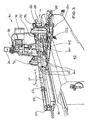
- the different recesses in the frame profile 10 are produced with a drilling-milling machine 40 as follows.
- the drilling and milling machine 40 has a base frame 42.
- this base frame 42 are those for operating the drilling-milling machine 40 required electrical and other supply lines, like pneumatic lines, and the required Electronics for controlling and operating the machine accommodated.
- the various can be controlled via a control panel 44 Units of the drilling-milling machine 40, as before control is described in more detail below.
- the control takes place in the present case above the respective frame profile and matched its intended recesses Operating programs.
- a support device 46 in X and Movable in Y direction On the base frame 42 is a support device 46 in X and Movable in Y direction. On this support device 46, the frame profile 10 to be processed is supported in such a way that it has its longitudinal axis 48 in the X direction the support device 46 rests.
- Fig. 2 that is Frame profile 10 shown schematically.
- a piston rod 52 which is in a cylinder 54 in the longitudinal direction X guided on the support device 46 adjustable is.
- the piston 52 moves out of the cylinder 54 so far that the foot-side end face 50 a predetermined distance 56 from the lower edge 58 of the recess 28 (Fig. 1). With the spacing 56, all the cutouts 28, according to their predetermined programming lower edge 58 are related.
- the frame profile 10 In the transverse direction, in the Y direction, the frame profile 10 by means of sideways in the present case against the left Side wall 12 acting buffer 60 held.
- This buffer 60 are provided on the front on corresponding piston rods, which are stored in cylinders 62 correspondingly extendable are. These buffers 60 and their piston rods become pneumatic emotional.
- the right side wall 14 of the frame profile 10, facing the buffers 60 is from a back wall 64 held.
- the frame profile 10 is in the transverse direction Y, thus clamped between the rear wall 64 and the buffers 60 held.
- a first drilling-milling device is on the base frame 42 70 available, the tool 72, which in the present case is a milling cutter, is aligned in the Z direction.
- the electric motor 74 can set the tool 72 in rotation become.
- the electric motor 74 with the tool 72 is on a Z-carriage 76 held by an electric motor 78 can be moved in the Z direction.
- When activating the Electric motor 78 can thus tool 72 in the frame profile Immerse 10.
- the support device 46 can do this on the support device 46 accordingly held in frame profile 10 X-Y direction can be traversed by driving the tool 72 the ones in the upper side surface 22 Recesses, such as the recess 28 (Fig. 2), made can be.
- the Z-carriage 76 is moved upwards, in the Z-direction, so that the tool 72 from the frame profile 10 upwards wanders out.
- Various tools can then be used with the tool 72 Recesses in the upper side surface 22 of the frame profile 10 are manufactured.
- This drilling and milling device 80 has a tool 82, which in the present case Is a milling cutter.
- the tool 82 with its driving Electric motor 84 is mounted on a Y-slide 86. This Y carriage 86 can be driven in the Y direction by an electric motor 88 be moved.
- a third drilling milling device 90 is the second drilling milling device 80, the frame profile 10 opposite, so positioned that tool 92 of the third drilling and milling device 90, which corresponds to the tool 82, with the Tool 82 lies on the same Y axis 93.
- the third drilling-milling device 90 has also an electric motor driving the tool 92 94, which corresponds to the electric motor 84 and which is on a Y-carriage 96, which corresponds to the Y-slide 86, attached is.
- the carriage 96 can by means of an electric motor 98, which corresponds to the electric motor 88, move in the Y direction become.
- the two tools 82, 92 have a first, front one Section 100, which is designed as a milling cutter. Subsequently there is a second section 102 which a larger cross section than the first section 100 has. This second section 102 is also as Milling cutter trained. Then there is a third section 104 present opposite the second section 102 has a smaller diameter.
- the procedure is as follows. With the help of the first and second section 100, 102 becomes the upper cross-sectional area 26.1 manufactured. For this, the second drilling-milling device 80 with the help of the electric motor 88 against and move into the left side wall 12. By further immersion of the tool 82 in the left side wall 12 can with the help of the third section 104 then as Longitudinal slot showing cross-sectional area 26.2 getting produced. For this purpose, the frame profile 10 and thus also the support device 46 correspondingly in the X direction method.
- the third drilling and milling device is used in a comparable manner 90 the existing on the right side wall 14 Recess 28 made.
- the recesses above the recesses 26, 28 30, 32 in the two side walls 12, 14 are also with the second or third drilling-milling device 80, 90 manufactured. These circular cutouts 30, 32 are so large that they match the second section 102 of the tool 82 or 92 are produced can.
- the frame profile 10 is moved in the X-Y direction by corresponding movement of the support device 46 in said X-Y direction.
- An electric motor 110 is used for moving in the X direction a pinion 112 drives accordingly.
- the pinion 112 meshes with a rack 114 which is in the X direction on the bottom the support device 46 is attached.
- the rack 114 and thus the Support device 46 in the X direction or in the opposite direction Move in the X direction.
- an electric motor 120 is used Motor 120 rotatably connected threaded spindle 122 can Support device 46 in Y-guides 124 adjusted back and forth become.
- the two Y slides 86, 96 can be adjusted in the Z direction the recesses 26, 30, 28, 32 in the Z direction to be able to attach variably. Because in a manufacturing company of door structures regularly the same in cross section Frame profiles 10 are used is an adjustment of generally do not have two Y-slides 86, 96 in the Z-direction required. Therefore this adjustment is also in view on a cost reduction of the corresponding drilling and milling machine in the present example only in manual mode intended. Of course it would also be possible for Z-adjustment of these two Y-slides 86, 96 each to provide electromotive drives.
- the three buffers 60 in the present case and their holders are slidably mounted in the X direction. This prevents that the buffers 60 in the area from the side can be incorporated recesses 26, 30, which the Operation of the second drilling milling device 80 could interfere.
- the buffers 60 are therefore always outside of those to be attached lateral recesses 26, 30 attached.
Landscapes
- Engineering & Computer Science (AREA)
- Mechanical Engineering (AREA)
- Life Sciences & Earth Sciences (AREA)
- Physics & Mathematics (AREA)
- Optics & Photonics (AREA)
- Wood Science & Technology (AREA)
- Forests & Forestry (AREA)
- Milling, Drilling, And Turning Of Wood (AREA)
- Processing Of Stones Or Stones Resemblance Materials (AREA)
Abstract
Description
- Fig. 1
- eine perspektivische Teilansicht eines Rahmenprofils, das von einer erfindungsgemäßen Bohr-Fräsmaschine mit Aussparungen versehen ist,
- Fig. 2
- eine schematisierte, die Funktion einer erfindungsgemäßen Bohr-Fräsmaschine verdeutlichende Darstellung,
- Fig. 3
- eine perspektivische Seitenansicht der Bohr-Fräsmaschine, mit den Bearbeitungsmöglichkeiten gem. Fig. 2 zum Bearbeiten eines Rahmenprofils gemäß Fig. 1.
Claims (19)
- Bohr-Fräsmaschine für eine bohrende und fräsende Herstellung von in Rahmenprofilen von Türkonstruktionen vorzusehenden Aussparungen von Türschließeinrichtungen,
gekennzeichnet durcheine in X-Y-Richtung ausgerichtete Auflagevorrichtung (46),die in X-Y-Richtung verfahrbar auf einem Grundgestell (42) gelagert ist undauf der zumindest eines der zu bearbeitenden Rahmenprofile (10), in X-Richtung ausgerichtet, flachliegend lagefixierbar auflagerbar ist,eine in Z-Richtung auf ein Rahmenprofil (10) einwirksame erste Bohr-Fräsvorrichtung (70),eine zweite und dritte Bohr-Fräsvorrichtung (80, 90), die in Y-Richtung auf das Rahmenprofil (10) einwirksam sind, wobei diese beiden Bohr-Fräsvorrichtungen (80, 90) aus zueinander entgegengesetzten Richtungen auf das Rahmenprofil (10) einwirksam sind,eine Regel- und Steuereinrichtung zum vorbestimmbaren, beliebigen Ansteuern der motorischen Antriebe zum Verstellen des Grundgestells (42), der drei Bohr-Fräsvorrichtungen (70, 80, 90) und zum Antreiben der drei Werkzeuge (72, 82, 92) dieser drei Bohr-Fräsvorrichtungen (70, 80, 90). - Bohr-Fräsmaschine nach Anspruch 1,
dadurch gekennzeichnet, dassdie zweite und dritte Bohr-Fräsvorrichtung (80, 90) längs derselben Y-Achse (93) ausgerichtet sind. - Bohr-Fräsvorrichtung nach einem der vorstehenden Ansprüche,
dadurch gekennzeichnet, dassdie erste Bohr-Fräsvorrichtung (70) einen elektromotorischen Antrieb (78) zum Verstellen des Bohr-Fräswerkzeuges (72) längs der Z-Achse hat. - Bohr-Fräsvorrichtung nach einem der vorstehenden Ansprüche,
dadurch gekennzeichnet, dassdie zweite Bohr-Fräsvorrichtung (80) einen elektromotorischen Antrieb (88) zum Verstellen des Bohr-Fräswerkzeuges (82) längs der Y-Achse (93) hat. - Bohr-Fräsvorrichtung nach einem der vorstehenden Ansprüche,
dadurch gekennzeichnet, dassdie dritte Bohr-Fräsvorrichtung (90) einen elektromotorischen Antrieb (98) zum Verstellen des Bohr-Fräswerkzeuges (92) längs der Y-Achse (93) hat. - Bohr-Fräsvorrichtung nach einem der vorstehenden Ansprüche,
dadurch gekennzeichnet, dassdie zweite Bohr-Fräsvorrichtung (80) in Z-Richtung parallel verstellbar ist. - Bohr-Fräsvorrichtung nach einem der vorstehenden Ansprüche,
dadurch gekennzeichnet, dassdie dritte Bohr-Fräsvorrichtung (90) in Z-Richtung parallel verstellbar ist. - Bohr-Fräsvorrichtung nach einem der vorstehenden Ansprüche,
dadurch gekennzeichnet, dassein motorischer Antrieb (110) zum Verstellen des Grundgestells (42) in X-Richtung und ein zweiter motorischer Antrieb (120) zum Verstellen des Grundgestells (42) in Y-Richtung vorhanden sind. - Bohr-Fräsvorrichtung nach Anspruch 8,
dadurch gekennzeichnet, dassein Ritzel-Zahnstangen-Antrieb (112, 114) für die Verstellung des Grundgestells (42) in X-Richtung vorhanden ist. - Bohr-Fräsvorrichtung nach Anspruch 8,
dadurch gekennzeichnet, dassein Spindeltrieb (122) für die Verstellung des Grundgestells (42) in Y-Richtung vorhanden ist. - Bohr-Fräsvorrichtung nach einem der vorstehenden Ansprüche,
dadurch gekennzeichnet, dasseine in X-Richtung verstellbare erste Puffervorrichtung zum Lagefixieren eines auf der Auflagevorrichtung (46) aufliegenden Rahmenprofils (10) vorhanden ist. - Bohr-Fräsvorrichtung nach Anspruch 11,
dadurch gekennzeichnet, dassdie erste Puffervorrichtung eine gegen die fußseitige Stirnfläche (50) des Rahmenprofils (10) einwirksame Kolben-Zylinder-Anordnung (52, 54) enthält. - Bohr-Fräsvorrichtung nach Anspruch 12,
dadurch gekennzeichnet, dassdie gegen die fußseitige Stirnfläche (50) des Rahmenprofils (10) verfahrbare Kolbenstange auf einen vorwählbaren X-Wert ausfahrbar ist. - Bohr-Fräsvorrichtung nach Anspruch 11 oder 12,
dadurch gekennzeichnet, dassdie erste Puffervorrichtung eine gegen die kopfseitige Stirnfläche des Rahmenprofils (10) einwirksame Kolben-Zylinder-Anordnung (53, 55) enthält. - Bohr-Fräsvorrichtung nach einem der vorstehenden Ansprüche,
dadurch gekennzeichnet, dasseine in Y-Richtung verstellbare zweite Puffervorrichtung zum Lagefixieren eines auf der Auflagevorrichtung (46) aufliegenden Rahmenprofils (10) vorhanden ist. - Bohr-Fräsvorrichtung nach Anspruch 15,
dadurch gekennzeichnet, dassdie zweite Puffervorrichtung mehrere, parallel zueinander ausgerichtete und mit gegenseitigem Abstand längs des Rahmenprofils (10) angeordnete Kolben-Zylinder-Anordnungen (60, 62) besitzt. - Bohr-Fräsvorrichtung nach Anspruch 16,
dadurch gekennzeichnet, dassdie Kolbenstangen der zweiten Puffervorrichtung gemeinsam aktivierbar sind. - Bohr-Fräsvorrichtung nach einem der Ansprüche 11 bis 17,
dadurch gekennzeichnet, dassdie Kolbenstangen der Kolben-Zylinder-Anordnungen pneumatisch bewegbar sind. - Bohr-Fräsvorrichtung nach einem der vorstehenden Ansprüche,
dadurch gekennzeichnet, dassdie zweite und dritte Bohr-Fräsvorrichtung (80, 90) jeweils einen Stufenfräser als Werkzeug (82, 92) besitzen, mit einem im Durchmesser kleineren (100), sich anschließenden größeren (102) und sich anschließenden wiederum kleineren (104) Fräsabschnitt.
Applications Claiming Priority (2)
| Application Number | Priority Date | Filing Date | Title |
|---|---|---|---|
| DE20100465U DE20100465U1 (de) | 2001-01-11 | 2001-01-11 | Bohr-Fräsmaschine zum Bearbeiten von Rahmenprofilen von Türkonstruktionen |
| DE20100465U | 2001-01-11 |
Publications (2)
| Publication Number | Publication Date |
|---|---|
| EP1222986A2 true EP1222986A2 (de) | 2002-07-17 |
| EP1222986A3 EP1222986A3 (de) | 2002-10-09 |
Family
ID=7951468
Family Applications (1)
| Application Number | Title | Priority Date | Filing Date |
|---|---|---|---|
| EP02000518A Withdrawn EP1222986A3 (de) | 2001-01-11 | 2002-01-09 | Bohr-Fräsmaschine zum Bearbeiten von Rahmenprofilen von Türkonstruktionen |
Country Status (2)
| Country | Link |
|---|---|
| EP (1) | EP1222986A3 (de) |
| DE (1) | DE20100465U1 (de) |
Cited By (6)
| Publication number | Priority date | Publication date | Assignee | Title |
|---|---|---|---|---|
| EP1588810A1 (de) * | 2004-04-15 | 2005-10-26 | Scagis s.r.l. | Maschine zum Fräsen und Bohren der zu verbindenden Enden von Profilen aus Holz oder Holz-Metall zur Herstellung von Rahmen, insbesondere Tür- und Fensterrahmen |
| US7159831B2 (en) | 2003-02-21 | 2007-01-09 | Carl-Zeiss-Stiftung | Adjusting device |
| CN102328210A (zh) * | 2011-09-09 | 2012-01-25 | 山东省淄博蠕墨铸铁股份有限公司 | 组合钻铣机床 |
| DE10330581B4 (de) * | 2002-08-23 | 2015-02-19 | Carl Zeiss Meditec Ag | Verstellvorrichtung |
| CN109926855A (zh) * | 2019-03-27 | 2019-06-25 | 广州会港智能装备有限公司 | 一种夹持位置可调的加工夹具及其加工装置 |
| EP3608052A1 (de) | 2018-07-23 | 2020-02-12 | Cesare Galdabini S.p.A. | Werkzeugmaschine zum bearbeiten prismatischer profile |
Families Citing this family (4)
| Publication number | Priority date | Publication date | Assignee | Title |
|---|---|---|---|---|
| WO2008143596A1 (en) * | 2007-05-22 | 2008-11-27 | Murat Makina Sanayi Ve Ticaret Limited Sirketi | Delay line with triple drilling and boring group for processing pvc sections |
| ITMO20090023A1 (it) * | 2009-01-30 | 2009-05-01 | Framar S R L | Macchina per la lavorazione automatica di sedi per mostrine quadre nei serramenti ed altri manufatti in legno e/o compositi e metodo relativo |
| CN106363711B (zh) * | 2016-11-16 | 2019-04-02 | 东阳市新和电子机械有限公司 | 一种新型数控榫卯机及其实现方法 |
| CN116551405B (zh) * | 2023-07-06 | 2023-11-03 | 山东辰禾智能装备有限公司 | 一种型材成框后定位加工装置及方法 |
Family Cites Families (3)
| Publication number | Priority date | Publication date | Assignee | Title |
|---|---|---|---|---|
| DE19526616A1 (de) * | 1994-07-21 | 1996-07-18 | Reiner Dorner | Verfahren zum Bearbeiten von Längsprofilen endlicher Länge |
| IT1283048B1 (it) * | 1996-05-21 | 1998-04-07 | Alberti Vittorio Spa | Dispositivo atto a comandare l'avanzamento passo a passo di pannelli, particolarmente studiato per macchine operatrici per lavorazioni |
| DE19641171A1 (de) * | 1996-10-08 | 1998-04-09 | Kurt Gautschi | Vorrichtung und Verfahren zum Bearbeiten von Fensterprofilen |
-
2001
- 2001-01-11 DE DE20100465U patent/DE20100465U1/de not_active Expired - Lifetime
-
2002
- 2002-01-09 EP EP02000518A patent/EP1222986A3/de not_active Withdrawn
Cited By (6)
| Publication number | Priority date | Publication date | Assignee | Title |
|---|---|---|---|---|
| DE10330581B4 (de) * | 2002-08-23 | 2015-02-19 | Carl Zeiss Meditec Ag | Verstellvorrichtung |
| US7159831B2 (en) | 2003-02-21 | 2007-01-09 | Carl-Zeiss-Stiftung | Adjusting device |
| EP1588810A1 (de) * | 2004-04-15 | 2005-10-26 | Scagis s.r.l. | Maschine zum Fräsen und Bohren der zu verbindenden Enden von Profilen aus Holz oder Holz-Metall zur Herstellung von Rahmen, insbesondere Tür- und Fensterrahmen |
| CN102328210A (zh) * | 2011-09-09 | 2012-01-25 | 山东省淄博蠕墨铸铁股份有限公司 | 组合钻铣机床 |
| EP3608052A1 (de) | 2018-07-23 | 2020-02-12 | Cesare Galdabini S.p.A. | Werkzeugmaschine zum bearbeiten prismatischer profile |
| CN109926855A (zh) * | 2019-03-27 | 2019-06-25 | 广州会港智能装备有限公司 | 一种夹持位置可调的加工夹具及其加工装置 |
Also Published As
| Publication number | Publication date |
|---|---|
| EP1222986A3 (de) | 2002-10-09 |
| DE20100465U1 (de) | 2001-03-15 |
Similar Documents
| Publication | Publication Date | Title |
|---|---|---|
| DE602006000545T2 (de) | Bearbeitungszentrum mit zwei Arbeitseinheiten mit Mitteln zur Handhabung des Werkstücks | |
| EP3943239B1 (de) | Werkzeugmaschine und verfahren zum betreiben der werkzeugmaschine | |
| DE102007022200B4 (de) | Werkzeugmaschine mit numerischer Steuerung | |
| DE4113629C2 (de) | Reihenbohr- und Fräsmaschine | |
| DE3823635A1 (de) | Einrichtung zur bearbeitung von profilstangen, insbesondere fuer die fenster- und tuerenherstellung | |
| DE102009019267A1 (de) | 4-Achsen-Werkzeugmaschine | |
| DE3633448A1 (de) | Schneidvorrichtung | |
| DE2747989A1 (de) | Bohrmaschine, insbesondere fuer glas- oder keramikwerkstuecke | |
| EP1677943A2 (de) | Aufspanntisch mit einer teleskoprohreinheit und einem saugteller aufweisenden spannelement | |
| DE4031911A1 (de) | Vorrichtung zum bearbeiten von stangen | |
| DE20100465U1 (de) | Bohr-Fräsmaschine zum Bearbeiten von Rahmenprofilen von Türkonstruktionen | |
| EP0787560B1 (de) | Vorrichtung zum Bearbeiten von Stangenmaterial, Profilen und dergleichen | |
| AT395835B (de) | Verfahren zum herstellen einer parallelachsigen rotationskolbenmaschine | |
| DE602006000992T2 (de) | Maschine zur Herstellung von Türrahmen | |
| AT521951B1 (de) | Werkzeugmaschine | |
| EP1125670B1 (de) | Verputzvorrichtung, insbesondere Schweissraupenputzmaschine | |
| DE4443512A1 (de) | Bearbeitungsmaschine für gerade und gekrümmte Werkstücke, insbesondere aus Holz | |
| DE102019003613A1 (de) | Verfahren zur Bearbeitung von Werkstücken aus Holz, Kunststoff und dergleichen | |
| EP0433788A2 (de) | Haltevorrichtung bzw. Schraubstock zum Festhalten von Werkstücken | |
| DE4014921C1 (de) | ||
| DE102016009430A1 (de) | Anlage und Verfahren zum Bearbeiten von Werkstücken aus Holz, Kunststoff und dergleichen | |
| DE3914008A1 (de) | Vorrichtung zum herstellen und bearbeiten von werkstuecken beliebiger geometrie | |
| DE69608372T2 (de) | Werkzeugmaschine für Bearbeitungsvorgänge auf langgestreckten Werkstücken wie Profilen und dergleichen | |
| DE8912243U1 (de) | Kurzhub-Werkzeugmaschine mit einem an einem Maschinengestell verfahrbar gelagerten Bohr- und Frässpindelstock | |
| EP3181276A1 (de) | Werkezugmaschine und verfahren zur feinbearbeitung |
Legal Events
| Date | Code | Title | Description |
|---|---|---|---|
| PUAI | Public reference made under article 153(3) epc to a published international application that has entered the european phase |
Free format text: ORIGINAL CODE: 0009012 |
|
| AK | Designated contracting states |
Kind code of ref document: A2 Designated state(s): AT BE CH CY DE DK ES FI FR GB GR IE IT LI LU MC NL PT SE TR |
|
| AX | Request for extension of the european patent |
Free format text: AL;LT;LV;MK;RO;SI |
|
| PUAL | Search report despatched |
Free format text: ORIGINAL CODE: 0009013 |
|
| AK | Designated contracting states |
Kind code of ref document: A3 Designated state(s): AT BE CH CY DE DK ES FI FR GB GR IE IT LI LU MC NL PT SE TR |
|
| AX | Request for extension of the european patent |
Free format text: AL;LT;LV;MK;RO;SI |
|
| 17P | Request for examination filed |
Effective date: 20030409 |
|
| AKX | Designation fees paid |
Designated state(s): DE |
|
| STAA | Information on the status of an ep patent application or granted ep patent |
Free format text: STATUS: THE APPLICATION IS DEEMED TO BE WITHDRAWN |
|
| 18D | Application deemed to be withdrawn |
Effective date: 20040803 |