EP1223013A2 - Vorrichtung und Strecke zur Sichterbeschickung - Google Patents
Vorrichtung und Strecke zur Sichterbeschickung Download PDFInfo
- Publication number
- EP1223013A2 EP1223013A2 EP02000668A EP02000668A EP1223013A2 EP 1223013 A2 EP1223013 A2 EP 1223013A2 EP 02000668 A EP02000668 A EP 02000668A EP 02000668 A EP02000668 A EP 02000668A EP 1223013 A2 EP1223013 A2 EP 1223013A2
- Authority
- EP
- European Patent Office
- Prior art keywords
- classifier
- distribution
- material flow
- rake
- width
- Prior art date
- Legal status (The legal status is an assumption and is not a legal conclusion. Google has not performed a legal analysis and makes no representation as to the accuracy of the status listed.)
- Withdrawn
Links
Images


Classifications
-
- B—PERFORMING OPERATIONS; TRANSPORTING
- B27—WORKING OR PRESERVING WOOD OR SIMILAR MATERIAL; NAILING OR STAPLING MACHINES IN GENERAL
- B27N—MANUFACTURE BY DRY PROCESSES OF ARTICLES, WITH OR WITHOUT ORGANIC BINDING AGENTS, MADE FROM PARTICLES OR FIBRES CONSISTING OF WOOD OR OTHER LIGNOCELLULOSIC OR LIKE ORGANIC MATERIAL
- B27N3/00—Manufacture of substantially flat articles, e.g. boards, from particles or fibres
- B27N3/08—Moulding or pressing
- B27N3/10—Moulding of mats
- B27N3/14—Distributing or orienting the particles or fibres
Definitions
- the invention relates to a device and a route for Sifter loading in the manufacturing process of wood fiber boards according to the preamble of claims 1, 6 and 9.
- the material flows from the gluing or drying systems are mostly used in the production of MDF boards via conveyor belt systems introduced that designed over longer distances are and therefore only relatively small widths of approx. 1 up to 1.5 m. Since the classifier systems work on the principle the wind separation work, the classifiers must be an even one Material flow in its entire feed width of approx. 3.5 m are fed. This usually happens over continuously running dosing belts with a range of also 3.5 m.
- intermediate bunkers used in which distribution and conveyor belts are provided were the fibers evenly to an approximately 3.5 m wide Have dispensed.
- Such intermediate bunkers require a relatively large construction effort and also need one relatively high space requirements, which also reduces the manufacturing costs of the fiberboard can be increased.
- processable Classifier quantities in individual wind classifier systems from physical The current sifter width is limited basically not significantly increased, so that with larger Material flows currently several wind classifier systems side by side must be used. So far, several parallel intermediate bunkers and dosing conveyor systems necessary, which the plant and space requirements for sifter feeding have also increased.
- the invention is therefore based on the object, the introduced To equalize material flows in front of each classifier, that a continuous classifier feed is made possible and this with the least possible outlay on equipment.
- the invention has the advantage that by the free fall of the Fiber flow in the conveyor channels of the vertical partition fan which slightly compacted due to their own weight Spread wood fibers by volume and thus the enlarging ones Fill the delivery channels evenly and thereby over the Width of the conveyor channels creates a uniform mass distribution becomes. This is also advantageous over the entire Feeder width of the classifier a uniform material flow Can be placed on a feed belt and thus in the classifier air flow recoverable.
- the invention advantageously also a considerable amount of space one that is particularly useful in the manufacture of fiberboard is particularly narrow in the horizontal direction, since the plate production is largely arranged in a row continuous horizontal work steps.
- the invention has the advantage that the broadening occurs during a short funding process, whereby the glued wood fibers due to the limited setting time can be pressed quickly after the widening process, which ensures a high quality standard in plate production remains guaranteed.
- the invention also has the advantage that the simple fan-like broadening of the feeder of the apparatus Effort is low, so that this leads to a reduction the production cost is achievable.
- the broadened material flow which is the capacity of a reformers exceeds evenly by a simple calculation system to divide between several wind classifiers, so that on simple How the plate production of a production line increases can be.
- MDF boards Medium Density Fibreboard
- the classifier feed section 2 serves primarily for Separation of heavy parts and lumps of glue that occur during the course of the drying and gluing process inevitably occur. These heavy parts must not be placed in the plate fleece reach, as this will reduce the quality of the plate and the sensitive ones during the continuous pressing process Press belts can be damaged.
- the glued wood fibers arrive after the gluing process by means of a relatively narrow conveyor belt 1 of approx. 1 m Width on the classifier feed line 2.
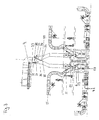
- the classifier feed line 2 consists of a vertical compartment 3, a weigh feeder 4, a rotary valve 5 and an air classifier 6, of which the wood fibers do not become one spreading station shown are promoted.
- the wood fibers After the promotion due to the relatively narrow conveyor belt 1, the wood fibers first fed to the vertical division fan 3, surrounded by a rectangular and tubular sheet metal housing is.
- the side walls 19 are in the vertical conveying direction 8 constant about 1 m wide while the pipe width transversely widened transversely to the conveying direction 8 downwards.
- the pipe width across the conveying direction is at the top the feed point at conveyor belt 1 about 1 to 1.5 m and the lower outlet opening about 3.5 m.
- FIG. 2 of the drawing is shown schematically.
- the contain like parts have the same reference numerals as in Fig. 1 of the Drawing.
- a transfer shaft 21 is arranged in the upper area, into which the wood fibers are introduced vertically from conveyor belt 1 become.
- the distribution compartment 3 is vertically below attached to the falling wood fibers over a width distributed transversely to the conveying direction 8, which at the outlet end of the Classifier width corresponds.
- These are expanded in the down Rectangular tube partitions 25 provided the total current divide into several separate streams.
- These partitions 25 are preferably designed as thin flat sheets, which are arranged along the flow. Between the partitions 25 and between the partitions 25 and the outer walls 22 thereby form parallel conveyor channels 23, which are downwards in width laterally and transversely to the conveying direction 8 widen.
- the width of the individual conveying channels 23 is through Longitudinal slots 29 in the mounting brackets 24 of the partitions 25, 26, 27 arranged adjustable.
- the mounting brackets 24 on the front and rear wall of the pipe housing preferably attached by means of a screw connection.
- the Delivery channels 23 are usually in the plate manufacturing process not adjustable, but can be attached to different conveyor belt and sifter widths can be adjusted.
- the partitions 25, 26, 27 are between the front and rear walls of the tube housing consistently arranged and have top and bottom oblique end sections, so that the fiber stream in the task and Exit area along the slopes in and out of the conveyor channels is discharged and there is no material jam can come.
- the sloping spout also provides additional support the distribution in width per partial material flow.
- the dosing belt scale 4 corresponds the width of the sifter and encourages you continuous fiber flow to one shown in Fig. 1 vertical conveyor shaft 11, under which the rotary valve 5 is arranged.
- the dosing belt scale 4 has a continuous Weighing device consisting of at least one weighing roller arrangement 9, which is supported on load cells and also includes a belt speed detection device, so that the feed rate to classifier 6 can be determined is.
- the binder dosage is determined via the determined delivery rate controllable.
- the tape running speed advantageously is adjustable.
- the distribution compartment 3 and the dosing belt scale 4 are in one common frame 10 attached to dust protection is clad with intermediate plates.
- the one on the dosing belt scale 4 conveyed fiber stream can have a head up to 1 m, and is at the end of the dosing belt scale 4 via a Dissolving head 18 in the conveyor shaft 11 to the rotary valve 5 scattered.
- the rotary valve 5 promotes the flow of material also continuously over a width of 3.5 m in the classifier 6 and serves mainly for pneumatic Separation of the classifier feed section 2 to the wind classifier 4th
- the classifier 6 has two wind feed pipes 12, 13, via which the preparerwindstrom 14 is brought up. The are in the Classifier wind flow 14 introduced wood fibers in a classifier flow chamber 16 pending and continuous an output 15 to the scattering station, not shown. Below the classifier chamber 16 is a collecting container 17 arranged for the heavy materials and lumps of glue in which these heavier parts fall out of the sifter stream 14 and be discarded.
- Such a classifying section 2 can be done in a simple manner the glued wood fibers continuously and over the whole Classifier width are fed uniformly to classifier 4, whereby the heavy parts and lumps of glue also from large quantities are separable.
- a classifier feed line is shown in Fig. 3 of the drawing.
- This classifier feed section differs from that in Fig. 1 shown only by the area after the dosing belt scale 4, so that only this part of the classifier loading section is shown in Fig. 3. It was for the functionally the same Parts used the same reference numbers as 1 and 2 of the drawing.
- Fig. 3 of the drawing is a classifier loading section shown for two similar air classifiers 6. With this Classifier feed sections are material flows of up to approx. 60 t / h processable.
- In the upper area is the one after the division fan 3 provided dosing belt scale 4 shown.
- This promotes the fiber stream to a splitting device 31 which the 3.5 m wide stream of material into two even fiber streams divided by 3.5 m wide.
- the splitting device 31 consists of a distribution chamber 32 with an upper one Inlet 33 and two lower outlets 34, 35 to the two rotary feeders 5.
- In the division chamber 32 is a division rake 36 and a guide flap 37 each around a pivot bearing 38, 39 arranged.
- the division rake 36 consists of a comb arranged teeth, which advantageously as Pipe pieces are formed and attached to a crossbar. There are preferably distances of approx. 50 mm is provided, the pipe sections also having a diameter of have about 50 mm. This rake 36 extends over the total chamber width, which is about the width of the weigh feeder 4 of 3.5 m corresponds.
- the division rake 36 is in the range of the upper inlet 33 diagonally opposite to the discharge point the dosing belt scale 4 arranged.
- Distribution rake 36 adjustable above a pivot point 38 stored and aligned to the vertical inclined inwards.
- the distribution flap 36 is opposite the guide flap 37 arranged, which is also rotatably mounted above.
- the Guide flap 37 also extends over the entire distribution chamber 32 and is designed as a closed sheet metal flap.
- the guide flap 37 is also opposite the vertical aligned inward so that between the guide flap 37 and the dividing rake 36 formed an acute angle becomes.
- the division rake 36 is used here Part of the material flow passed through the spaces between the pipes and the other part down the pipes to the second Outlet 35 promoted. Through the guide flap 37 the material flow more or less for the division rake 36 passed and thus directed towards the second outlet 34.
- both steering means 37, 36 allows one sensitive adjustment of the distribution on the two outlets 34, 35, so that the same delivery rates are always in each outlet can be initiated.
- Between the outlets 34, 35 is an acute one Separating edge 40 is provided, on which the guide flap 37 and the dividing rake 36 can be aligned and which is an exact one enables trouble-free introduction into the outlets 34, 35.
- Below each outlet 34, 35 is a cellular wheel sluice 5 and a wind sifter 6 with a collecting container 17 as in Fig. 1 of the drawing.
- the drawing is additionally a wind generating device 41 for each each air classifier 5 shown, the horizontal at the bottom of the Manufacturing hall is arranged and the classifier air to the Wind feed tubes 12, 13 promotes.
Landscapes
- Life Sciences & Earth Sciences (AREA)
- Engineering & Computer Science (AREA)
- Manufacturing & Machinery (AREA)
- Wood Science & Technology (AREA)
- Forests & Forestry (AREA)
- Dry Formation Of Fiberboard And The Like (AREA)
- Sorting Of Articles (AREA)
- Paper (AREA)
Abstract
Description
- Fig. 1:
- eine Sichterbeschickungsstrecke zwischen einer Beleimungsstation und einer Streustation mit einem Windsichter;
- Fig. 2:
- einen Aufteilungsfächer in der Sichterbeschickungsstrecke, und
- Fig. 3:
- einen Teil einer Sichterbeschickungsstrecke zwischen Dosierbandwaage und Streustation mit zwei Windsichtern.
Claims (10)
- Vorrichtung zur Sichterbeschickung bei Anlagen zur Herstellung von Holzfaserplatten bei der vor den Sichtern Verteilungsvorrichtungen vorgesehen sind, die den herangeführten Materialstrom von beleimten Holzfasern kontinuierlich dem Sichter zuführen, dadurch gekennzeichnet, daß als Verteilungsvorrichtung ein Aufteilungsfächer (3) vorgesehen ist, der aus einem vertikal angeordneten Rohr besteht, in dem längs und in Förderrichtung (8) Trennwände (25, 26, 27) vorgesehen sind, die den aufgegebenen Materialstrom in sich verbreiternde Förderkanäle (23) aufteilen.
- Vorrichtung zur Sichterbeschickung nach Anspruch 1, dadurch gekennzeichnet, daß der Aufteilungsfächer (3) als Rechteckrohr ausgebildet ist, zwischen dessen Vorderund Rückwand über die gesamte Rohrbreite mehrere Trennwände (25, 26, 27) angeordnet sind, die die Förderkanäle (23) bilden, dessen Breiten sich zur Austrittsöffnung vergrößern.
- Vorrichtung nach Anspruch 1 oder 2, dadurch gekennzeichnet, daß das Rechteckrohr mindestens eine Austrittsbreite von mindestens drei Metern aufweist und über mindestens sechs Förderkanäle (23) verfügt, wobei die Austrittsbreite des Rechteckrohrs ein Vielfaches der Austrittstiefe (Breite der Seitenwände 19) des Rechteckrohrs beträgt.
- Vorrichtung nach einem der vorhergehenden Ansprüche, dadurch gekennzeichnet, daß das Verhältnis der Einlaß- zur Auslaßbreite der Förderkanäle (23) fest oder einstellbar ist.
- Vorrichtung nach einem der vorhergehenden Ansprüche, dadurch gekennzeichnet, daß die Trennwände (25, 26, 27) im Einlaß- und/oder Austrittsbereich gegenüber der Horizontalen schräg oder rund ausgebildet sind, oder schräge und runde Einlaß- und Austrittsbereiche enthalten.
- Vorrichtung zur Sichterbeschickung bei Anlagen zur Herstellung von MDF-Platten, bei der vor den Sichtern Verteilungsvorrichtungen vorgesehen sind, die den herangeführten Materialstrom aus beleimten Holzfasern kontinuierlich den Sichtern zuführen, dadurch gekennzeichnet, daß die Verteilungsvorrichtung als Aufteilungsvorrichtung (31) mit einem Aufteilungsrechen (36) und einem Leitblech (37) ausgebildet ist, die den Materialstrom in zwei Teilströme aufteilt.
- Vorrichtung nach Anspruch 6, dadurch gekennzeichnet, daß der Aufteilungsrechen (36) kammartig angeordnete Zähne mit vorgegebenen Zwischenräumen enthält, durch die ein Teilstrom des beleimten Fasermaterials hindurch gelangt, wobei die Neigung des Rechens (36) gegenüber der Vertikalen fest oder einstellbar ist.
- Vorrichtung nach Anspruch 7, dadurch gekennzeichnet, daß das Leitblech gegenüberliegend zum Rechen (36) angeordnet ist und als weitgehend geschlossenes Teil ausgebildet ist, wobei die Neigung des Leitblechs (37) gegenüber der Vertikalen fest oder einstellbar ist und mit dem Rechen (36) einen spitzen Winkel bildet.
- Sichterbeschickungsstrecke bei Anlagen zur Herstellung von Holzfaserplatten, die aus Förder-, Verteil- und Sichtervorrichtungen besteht, dadurch gekennzeichnet, daß mindestens ein Aufteilungsfächer (3) als Verteilvorrichtung, eine Dosierbandwaage (4) oder ein Förderband als Fördervorrichtung und ein Windsichter (6) als Sichtervorrichtung vorgesehen ist.
- Sichterbeschickungsstrecke nach Anspruch 9, dadurch gekennzeichnet, daß als eine weitere Verteilvorrichtung eine Aufteilungsvorrichtung (31) mit Aufteilungsrechen (36) und Leitblech (37) vorgesehen ist, die den verbreiterten Materialstrom auf mindestens zwei Sichtervorrichtungen (6) aufteilt.
Applications Claiming Priority (2)
| Application Number | Priority Date | Filing Date | Title |
|---|---|---|---|
| DE10101380 | 2001-01-13 | ||
| DE2001101380 DE10101380B4 (de) | 2001-01-13 | 2001-01-13 | Sichterbeschickungungsstrecke bei Anlagen zur Herstellung von Holzfaserplatten |
Publications (2)
| Publication Number | Publication Date |
|---|---|
| EP1223013A2 true EP1223013A2 (de) | 2002-07-17 |
| EP1223013A3 EP1223013A3 (de) | 2005-08-10 |
Family
ID=7670479
Family Applications (1)
| Application Number | Title | Priority Date | Filing Date |
|---|---|---|---|
| EP02000668A Withdrawn EP1223013A3 (de) | 2001-01-13 | 2002-01-11 | Vorrichtung und Strecke zur Sichterbeschickung |
Country Status (2)
| Country | Link |
|---|---|
| EP (1) | EP1223013A3 (de) |
| DE (1) | DE10101380B4 (de) |
Families Citing this family (3)
| Publication number | Priority date | Publication date | Assignee | Title |
|---|---|---|---|---|
| DE20203427U1 (de) * | 2002-03-02 | 2003-04-17 | BINOS TECHNOLOGIES GmbH & Co. KG, 31832 Springe | Vorrichtung zur Herstellung eines Vlieses |
| DE102006047002A1 (de) * | 2006-10-02 | 2008-04-03 | Dieffenbacher Gmbh + Co. Kg | Verfahren, Vorrichtung und Anlage zum Feststellen und Ausscheiden von Unregelmäßigkeiten aus einem bewegten Materialstrom im Zuge der Herstellung von Werkstoffplatten |
| DE102006058626B3 (de) * | 2006-12-13 | 2008-04-10 | Siempelkamp Maschinen- Und Anlagenbau Gmbh & Co. Kg | Anlage zum Beleimen von Fasern für die Herstellung von Faserplatten, insbesondere MDF-Platten oder dergleichen Holzwerkstoffplatten |
Family Cites Families (6)
| Publication number | Priority date | Publication date | Assignee | Title |
|---|---|---|---|---|
| DE2422487C3 (de) * | 1974-05-09 | 1980-08-21 | Bison-Werke Baehre Und Greten Gmbh & Co Kg, 3257 Springe | Verfahren zum Aufstreuen eines Vlieses aus unsortierten Bestandteilen, vorzugsweise pflanzlicher Herkunft auf ein kontinuierlich bewegtes Förderband o.dgl. und eine Einrichtung zur Ausübung des Verfahrens |
| DE2942163A1 (de) * | 1979-10-18 | 1981-04-30 | Carl Schenck Ag, 6100 Darmstadt | Verfahren und vorrichtung zum aufteilen eines foerderstromes |
| DE3766247D1 (de) * | 1987-05-23 | 1990-12-20 | Schenck Ag Carl | Verfahren zum streuen eines spaenevlieses. |
| DE3717529A1 (de) * | 1987-05-25 | 1988-12-15 | Kartini Hans Georg Dipl Ing | Verfahren und vorrichtung zur bestimmung der fuer deren verarbeitung wichtigen eigenschaftswerte von holzspaenen, natuerlichen fasern oder dergleichen materialien |
| DE4113843A1 (de) * | 1991-04-27 | 1992-10-29 | Siempelkamp Gmbh & Co | Anlage fuer die aufbereitung und das streuen des streugutes zu streugutmatten im zuge der herstellung von faserplatten mit mittelschicht sowie oberer und unterer deckschicht |
| DE19916447A1 (de) * | 1999-04-12 | 2000-10-19 | Dieffenbacher Schenck Panel | Formstation |
-
2001
- 2001-01-13 DE DE2001101380 patent/DE10101380B4/de not_active Expired - Fee Related
-
2002
- 2002-01-11 EP EP02000668A patent/EP1223013A3/de not_active Withdrawn
Also Published As
| Publication number | Publication date |
|---|---|
| DE10101380A1 (de) | 2002-07-18 |
| EP1223013A3 (de) | 2005-08-10 |
| DE10101380B4 (de) | 2008-12-24 |
Similar Documents
| Publication | Publication Date | Title |
|---|---|---|
| EP1171269B1 (de) | Formstation | |
| DE2804413C3 (de) | Verfahren und Vorrichtung zum Beschicken einer Karde | |
| DE2942163C2 (de) | ||
| EP0109456B1 (de) | Verfahren und Vorrichtung zum Vergleichmässigen der Dichteverteilung in einer Kunstholzplatte | |
| EP0292581B1 (de) | Verfahren zum Streuen eines Spänevlieses | |
| DE10206595A1 (de) | Streustation zum homogenen Streuen von beleimten Streugütern insbesondere Holzspänen | |
| DE19835419A1 (de) | Vorrichtung und Verfahren zur Windsichtung | |
| DE3626053C2 (de) | ||
| AT412146B (de) | Vorrichtung zum sortieren von holzspänen in getrennte teilmengen | |
| DE68911533T2 (de) | Windsichter für produktteilchen. | |
| EP0069162B1 (de) | Verfahren zur Beeinflussung der Dichteverteilung eines zu streuenden Spänevlieses und Vorrichtung hierzu | |
| DE102017124063A1 (de) | Streuanlage und Verfahren zur Herstellung einer Streugutmatte im Zuge der Herstellung von Werkstoffplatten | |
| DE10101380B4 (de) | Sichterbeschickungungsstrecke bei Anlagen zur Herstellung von Holzfaserplatten | |
| EP1171268B1 (de) | Streustation für faserplatten | |
| DE1482452C3 (de) | Windsichter mit mehreren mit Ab stand übereinander angeordneten, von Sichtluft quer durchströmten Sicht gruppen | |
| DE10304147A1 (de) | Vorrichtung zum Streuen von Streugut auf eine kontinuierlich bewegte Unterlage sowie Bunker für die Vorrichtung zum Streuen von Streugut | |
| DE4326148B4 (de) | Einrichtung zur Streuung von Fasern, insbesondere von Spänen | |
| DE2422487C3 (de) | Verfahren zum Aufstreuen eines Vlieses aus unsortierten Bestandteilen, vorzugsweise pflanzlicher Herkunft auf ein kontinuierlich bewegtes Förderband o.dgl. und eine Einrichtung zur Ausübung des Verfahrens | |
| DE102016117383B4 (de) | Sichter | |
| DE2847109C3 (de) | Vorrichtung zum Streuen eines Vlieses | |
| DE2032128A1 (de) | Walzen-Austragskopf | |
| EP1328382A1 (de) | Vertikalbunker zur herstellung von holzwerkstoffplatten | |
| DE3435026A1 (de) | Einrichtung zum vermeiden von ueberlastungen von foerdereinrichtungen | |
| DE1728502C3 (de) | Streueinrichtung zur Herstellung mehrschichtiger Spänevliese | |
| DE1507685C (de) | Aufgabevornchtung fur einen Steig rohrsichter |
Legal Events
| Date | Code | Title | Description |
|---|---|---|---|
| PUAI | Public reference made under article 153(3) epc to a published international application that has entered the european phase |
Free format text: ORIGINAL CODE: 0009012 |
|
| AK | Designated contracting states |
Kind code of ref document: A2 Designated state(s): AT BE CH CY DE DK ES FI FR GB GR IE IT LI LU MC NL PT SE TR |
|
| AX | Request for extension of the european patent |
Free format text: AL;LT;LV;MK;RO;SI |
|
| RAP1 | Party data changed (applicant data changed or rights of an application transferred) |
Owner name: DIEFFENBACHER GMBH & CO. KG |
|
| PUAL | Search report despatched |
Free format text: ORIGINAL CODE: 0009013 |
|
| AK | Designated contracting states |
Kind code of ref document: A3 Designated state(s): AT BE CH CY DE DK ES FI FR GB GR IE IT LI LU MC NL PT SE TR |
|
| AX | Request for extension of the european patent |
Extension state: AL LT LV MK RO SI |
|
| STAA | Information on the status of an ep patent application or granted ep patent |
Free format text: STATUS: THE APPLICATION HAS BEEN WITHDRAWN |
|
| 18W | Application withdrawn |
Effective date: 20060123 |