EP1223029A2 - Vorrichtung zum Einsetzen von Giesstüllen in Dosen - Google Patents
Vorrichtung zum Einsetzen von Giesstüllen in Dosen Download PDFInfo
- Publication number
- EP1223029A2 EP1223029A2 EP02000687A EP02000687A EP1223029A2 EP 1223029 A2 EP1223029 A2 EP 1223029A2 EP 02000687 A EP02000687 A EP 02000687A EP 02000687 A EP02000687 A EP 02000687A EP 1223029 A2 EP1223029 A2 EP 1223029A2
- Authority
- EP
- European Patent Office
- Prior art keywords
- seat
- casing
- spout
- insertion device
- hammer
- Prior art date
- Legal status (The legal status is an assumption and is not a legal conclusion. Google has not performed a legal analysis and makes no representation as to the accuracy of the status listed.)
- Granted
Links
Images



Classifications
-
- B—PERFORMING OPERATIONS; TRANSPORTING
- B31—MAKING ARTICLES OF PAPER, CARDBOARD OR MATERIAL WORKED IN A MANNER ANALOGOUS TO PAPER; WORKING PAPER, CARDBOARD OR MATERIAL WORKED IN A MANNER ANALOGOUS TO PAPER
- B31B—MAKING CONTAINERS OF PAPER, CARDBOARD OR MATERIAL WORKED IN A MANNER ANALOGOUS TO PAPER
- B31B50/00—Making rigid or semi-rigid containers, e.g. boxes or cartons
-
- B—PERFORMING OPERATIONS; TRANSPORTING
- B31—MAKING ARTICLES OF PAPER, CARDBOARD OR MATERIAL WORKED IN A MANNER ANALOGOUS TO PAPER; WORKING PAPER, CARDBOARD OR MATERIAL WORKED IN A MANNER ANALOGOUS TO PAPER
- B31B—MAKING CONTAINERS OF PAPER, CARDBOARD OR MATERIAL WORKED IN A MANNER ANALOGOUS TO PAPER
- B31B50/00—Making rigid or semi-rigid containers, e.g. boxes or cartons
- B31B50/74—Auxiliary operations
- B31B50/81—Forming or attaching accessories, e.g. opening devices, closures or tear strings
- B31B50/84—Forming or attaching means for filling or dispensing contents, e.g. valves or spouts
Definitions
- the present invention relates to an insertion device for a machine for inserting pouring spouts in containers, as specified in the preamble to Claim 1.
- retractable elements made of cardboard or metal usually aluminium
- pouring spouts are commonly fitted in containers or packages, generally made of cardboard, which usually have rectangular cross-sections and are used in particular for products in granular or powder form such as, for example, soluble food products.
- the spouts are formed and fitted on the respective containers by suitable insertion machines cooperating with means for transporting the containers, such as chain conveyor lines.
- Figure 4 is a plan view of a rotary insertion machine, generally indicated 1, having a carousel structure which can be rotated by suitable drive means about a vertical axis coincident with the axis of a pin 2.
- the machine is positioned tangentially relative to a conveyor line, generally indicated 10, for example, with single or double chains, by means of which containers or packages 11, equally spaced on the conveyor line, are supplied at a constant speed.
- the insertion machine comprises a forming mechanism (not shown) which is supplied with a suitably-shaped strip of the material, generally aluminium or cardboard, of which the pouring spouts are made.
- the forming mechanism cuts off a portion of strip corresponding to a single pouring spout, gives it its final shape and, finally, inserts a spout 15 thus formed in one of the insertion devices 20 which will insert the spout in a corresponding container.
- the insertion devices which are equally angularly spaced around the periphery of the rotatable structure 3 of the insertion machine 1, are controlled by cam guides 4, 5 which impart to them a path of movement and an angular orientation corresponding to those of the containers 11 transported by the line 10.
- the feeding speed of the containers and the angular velocity of the devices for inserting the pouring spouts are synchronized with one another so that the devices are introduced into the spaces between two consecutive containers in the working region (the extent of which is indicated schematically by the segment A-B).
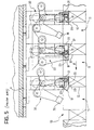
- Each insertion device 20 is provided ( Figure 5) with a thrust element or hammer 21 which is mounted in a seat 25 in a casing 22 and which can translate with a reciprocating rectilinear motion within the seat, between a retracted position in which a spout 15 can be received in the seat and a forward position in which the hammer pushes the spout out of the seat 25 into abutment with a container 11.
- the thrust element or hammer 21 also cooperates with a reaction element or anvil 50.
- the reaction element is translated towards the inside of a container, against the (inner) face of the respective wall opposite the (outer) face to which a pouring spout will be applied.
- the thrust element is moved forwards, guided by respective guide elements formed inside the casing 22, against the reaction element, so as to press the pouring spout against the container wall and to fix it (so that it is secured firmly by gluing or clinching).
- the insertion device Upon completion of the working phase, the insertion device continues to be moved along a predetermined path as a result of the rotation of the carousel until it arrives in front of the forming mechanism again, where it collects another pouring spout and then reaches the working region, along which it inserts the spout in a further container, and so on, in accordance with a cyclic mode of operation.
- Figures 6A and 6B of the appended drawings which have been extracted from United States patent No. 3 385 248, show an insertion device, generally indicated 20, as is used in conventional rotary insertion machines.
- Figure 6A is a side view of the device and Figure 6B shows the device in a horizontal view from above, sectioned on the line C-C, as indicated in Figure 6A.
- the thrust element or hammer 21 mounted in the seat 25 in a respective casing 22 forming part of a device 20 for inserting pouring spouts 15 has a substantially prismatic shape, rectangular in plan, with a predominant dimension along the axis of insertion of the spout, indicated by the arrow F.
- the hammer can be moved inside its casing, in the manner of a piston, with a reciprocating linear movement along the insertion axis.
- This axis is perpendicular to the plane of the working face 23 of the hammer, which has the function of pushing a spout against a corresponding container.
- the casing 22 in which the hammer 21 slides has a substantially inverted U-shaped cross-section so as to be able to receive in its seat 25 a pouring spout coming from the forming mechanism (not shown).
- the pouring spout remains temporarily held in the seat in the hammer casing by the friction against the side walls of the casing, by virtue of the fact that its lateral fins tend to open out resiliently, thus exerting a thrust force on the walls.
- the pouring spout has to be pushed against the wall 12 of the container 11 by means of the hammer which can slide along linear guides 24 formed on the internal side walls of the casing.
- the operation of the hammer which has to perform a stroke substantially equal to the dimension of the spout along the insertion axis F, is brought about by means of a control lever 30 mounted firmly on the insertion device 20.
- the control lever which is pivotable about a vertical axis 31, comprises two arms 32, 33 disposed on opposite sides of its pivot axis.
- An idle roller 34 mounted on the end of the arm 32 engages a guide ramp 35 formed on the fixed portion of the machine in the working region, causing the lever 30 to pivot in accordance with a predetermined rule of movement.
- the other arm 33 the end of which is articulated to the hammer 21, exerts a thrust force on the hammer as a result of the pivoting of the control lever 30.
- the hammer is thus caused to move forwards in its casing 22, in the direction of the arrow F, towards the face of the wall 12 to which the pouring spout is to be applied whilst, in the meantime, the anvil 25 is moved downwards into the container 11 with a rectilinear motion along an oblique axis inclined towards the opposite face of the wall 12.
- the pouring spout is inserted in the wall 12 of the respective container, by virtue of the fact that the spout and the wall are clamped between the hammer and the anvil.
- the main disadvantage of an insertion device of this type is that it is difficult to reconcile the conflicting requirements for the hammer casing to occupy little space along the insertion axis and for the risk of the hammer jamming inside the casing to be eliminated.
- the requirement for the hammer casing to occupy little space along the axis of insertion of the pouring spouts, that is, in the direction of transportation of the containers, is due to the need to reduce the gap between two consecutive packages to the minimum in order to increase the number of containers which reach the working region per unit of time, for a given linear speed of the conveyor line, and hence the productivity of the process.
- each of the devices 20 for the insertion of the pouring spouts has to be moved in a manner such as to be positioned in the gap between two consecutive containers at the start of the working region (point A), and to follow a straight path substantially coincident with the direction of movement of the containers until the insertion operation is completed.
- the maximum dimension of the hammer casing in the longitudinal direction (the term longitudinal refers hereinafter to the direction of insertion of the pouring spouts) is represented by the gap between two consecutive containers but, in practice, is further limited by the need to "link" the circular path of the insertion device to the straight path of movement of the containers at the start of the working region (point A).
- the longitudinal dimension of the hammer casing is determined by the sum of the longitudinal space occupied by the hammer (its thickness) and the stroke of the hammer, the stroke being substantially equal to the longitudinal dimension of the pouring spout.
- the jamming phenomenon is due to the necessary presence of clearance between the hammer and its guides and to the fact that the thrust force exerted on the hammer by the control lever during its pivoting movement is not purely longitudinal, but has also transverse components.
- the object of the present invention is to provide a device for inserting pouring spouts which occupies little space longitudinally and is free of risks of jamming of the thrust element inside its casing, in order to increase the productivity of the insertion process.
- a device 20 for inserting pouring spouts for rotary insertion machines comprises a thrust element or hammer 21, a casing 22 provided with a seat 25, a linear guide 24, a control lever 30, and a reaction element or anvil 50.
- the hammer 21 comprises two elements 26 and 27, that is, a lower element and an upper element, respectively, having the form of elongate plates of substantially rectangular cross-section, extending substantially vertically, and connected to one another, in conventional manner, by means of screws.
- the upper element 27 is welded perpendicularly to or formed integrally with a plate-like element 28 extending horizontally and in turn secured to a movable element or slide 29 which can slide on the linear guide 24.
- the set of elements 27, 28 and 29 constituting the upper portion of the hammer 21 is indicated 21b in Figures 1 and 2.
- the movable element or slide 29 preferably has sliding surfaces 29a, 29b made of material with a low friction coefficient.
- a slide 29 of a length such as to prevent risks of jamming, for example, a slide advantageously having a longitudinal dimension of the sliding surface which is comparable to or greater than its transverse dimension, as can be seen in Figures 1 and 2.
- the element 26 of the hammer 21 has a substantially rectangular longitudinal section with gradually reducing thicknesses towards its lower end.
- the thickness of the hammer is significantly less than the thickness to be seen at the level of the region in which it is fixed to the upper element 27. It is therefore possible to achieve the objective of reducing the longitudinal space occupied by the casing 22 and hence the gap between two consecutive containers.
- the working stroke of the hammer is controlled by the lever 30 which comprises two arms 32 and 33 and can pivot about a vertical axis 31.
- An idle roller 34 mounted on the free end of the arm 32 engages a ramp-like guide (not shown) mounted on the fixed portion of the machine in the working region in which the insertion device is guided along a straight path substantially coincident with that of the movement of the containers.
- a blade-like element 36 formed at the free end of the other arm 33 engages the lower portion 21a of the hammer.
- the hammer In rest conditions, the hammer is held in the retracted position inside its casing 22 by means of a resilient biasing element 45 such as, for example, a helical spring (shown schematically in Figure 1).
- the resilient element is preferably mounted between the movable element or slide 29 of the hammer and a fixed part of the insertion device 20.
- the control lever 30 is held in the rest position (indicated A in Figure 3) by means of a resilient biasing element 37 such as, for example, a helical spring.
- control lever and the hammer Upon completion of the insertion operation, the control lever and the hammer finally return to their respective rest positions by virtue of the biasing forces exerted by the respective resilient elements 45 and 37.
Landscapes
- Making Paper Articles (AREA)
- Auxiliary Devices For And Details Of Packaging Control (AREA)
- Filling Of Jars Or Cans And Processes For Cleaning And Sealing Jars (AREA)
- Automatic Analysis And Handling Materials Therefor (AREA)
- Automatic Assembly (AREA)
Applications Claiming Priority (2)
| Application Number | Priority Date | Filing Date | Title |
|---|---|---|---|
| IT2001TO000023A ITTO20010023A1 (it) | 2001-01-16 | 2001-01-16 | Dispositivo di inserimento per macchine inseritrici di beccucci erogatori su contenitori. |
| ITTO010023 | 2001-01-16 |
Publications (3)
| Publication Number | Publication Date |
|---|---|
| EP1223029A2 true EP1223029A2 (de) | 2002-07-17 |
| EP1223029A3 EP1223029A3 (de) | 2003-04-09 |
| EP1223029B1 EP1223029B1 (de) | 2005-03-30 |
Family
ID=11458378
Family Applications (1)
| Application Number | Title | Priority Date | Filing Date |
|---|---|---|---|
| EP02000687A Expired - Lifetime EP1223029B1 (de) | 2001-01-16 | 2002-01-11 | Vorrichtung zum Einsetzen von Giesstüllen in Dosen |
Country Status (6)
| Country | Link |
|---|---|
| EP (1) | EP1223029B1 (de) |
| AT (1) | ATE292014T1 (de) |
| BR (1) | BR0200049B1 (de) |
| DE (1) | DE60203415T2 (de) |
| ES (1) | ES2239179T3 (de) |
| IT (1) | ITTO20010023A1 (de) |
Cited By (1)
| Publication number | Priority date | Publication date | Assignee | Title |
|---|---|---|---|---|
| US20140083061A1 (en) * | 2012-09-26 | 2014-03-27 | Toyo Jidoki Co., Ltd | Method and Apparatus for Manufacturing Spout-Equipped Bags |
Family Cites Families (2)
| Publication number | Priority date | Publication date | Assignee | Title |
|---|---|---|---|---|
| US2998788A (en) * | 1958-08-20 | 1961-09-05 | Interstate Folding Box Co | Device for forming and applying pouring spouts to containers |
| US3025813A (en) * | 1959-12-14 | 1962-03-20 | Seal Spout Corp | Spout inserting machine |
-
2001
- 2001-01-16 IT IT2001TO000023A patent/ITTO20010023A1/it unknown
-
2002
- 2002-01-11 AT AT02000687T patent/ATE292014T1/de not_active IP Right Cessation
- 2002-01-11 DE DE60203415T patent/DE60203415T2/de not_active Expired - Lifetime
- 2002-01-11 ES ES02000687T patent/ES2239179T3/es not_active Expired - Lifetime
- 2002-01-11 EP EP02000687A patent/EP1223029B1/de not_active Expired - Lifetime
- 2002-01-14 BR BRPI0200049-0A patent/BR0200049B1/pt not_active IP Right Cessation
Cited By (1)
| Publication number | Priority date | Publication date | Assignee | Title |
|---|---|---|---|---|
| US20140083061A1 (en) * | 2012-09-26 | 2014-03-27 | Toyo Jidoki Co., Ltd | Method and Apparatus for Manufacturing Spout-Equipped Bags |
Also Published As
| Publication number | Publication date |
|---|---|
| EP1223029A3 (de) | 2003-04-09 |
| BR0200049A (pt) | 2002-10-22 |
| ITTO20010023A0 (it) | 2001-01-16 |
| ATE292014T1 (de) | 2005-04-15 |
| ES2239179T3 (es) | 2005-09-16 |
| DE60203415T2 (de) | 2006-03-09 |
| ITTO20010023A1 (it) | 2002-07-16 |
| EP1223029B1 (de) | 2005-03-30 |
| DE60203415D1 (de) | 2005-05-04 |
| BR0200049B1 (pt) | 2010-09-08 |
Similar Documents
| Publication | Publication Date | Title |
|---|---|---|
| EP3705199B1 (de) | Betätigungsmechanismus für eine senkrecht orientierte maschine zur herstellung von dosenkörpern | |
| EP2931634B1 (de) | Dosenkörperentnahmemechanismus für eine maschine mit einer vertikalachse zur herstellung von dosenkörpern | |
| JPS6138026B2 (de) | ||
| US20180200778A1 (en) | Apparatus for stacking and aligning laminar members blanked respectively and transporting the stacked and aligned laminar members to conveyor | |
| US7654384B1 (en) | Adjustable conveyor for varied size and shape containers | |
| KR20120135272A (ko) | 분절된 신장 워크피스를 운반하기 위한 운반장치 | |
| US9314036B2 (en) | Clipping tool assembly with crank shaft | |
| KR20170101945A (ko) | 브러쉬 스터핑 머신 | |
| WO2019180786A1 (ja) | 曲げ加工装置 | |
| DK2570206T3 (en) | Profile rolling machine | |
| US5558611A (en) | Apparatus for shaping blanks for hinge-lid packs with especially rounded longitudinal edges | |
| EP1223029B1 (de) | Vorrichtung zum Einsetzen von Giesstüllen in Dosen | |
| JP2019509898A (ja) | シェル用のシェルシステム配置アセンブリ | |
| EP3828106B1 (de) | Transportvorrichtung für behälter und verfahren zum an-/abhängen eines behälterträgers an einen bzw. von einem wagen | |
| US6481261B1 (en) | Feed mechanism | |
| US5794481A (en) | Device for bending or curving hollow-section strips | |
| US4705158A (en) | Cup feed apparatus | |
| US7117713B2 (en) | Terminal crimping machine | |
| US6385945B1 (en) | Packaging machine | |
| US20070186508A1 (en) | Cartoning machine | |
| KR101320523B1 (ko) | 포머 절단부 충격완화장치 | |
| KR101828842B1 (ko) | 절단 장치 | |
| US5147080A (en) | Staple forming and stapling machine | |
| US3385248A (en) | Machine for attaching spouts to containers | |
| CN105142455B (zh) | 停止用板弹簧成形机 |
Legal Events
| Date | Code | Title | Description |
|---|---|---|---|
| PUAI | Public reference made under article 153(3) epc to a published international application that has entered the european phase |
Free format text: ORIGINAL CODE: 0009012 |
|
| AK | Designated contracting states |
Kind code of ref document: A2 Designated state(s): AT BE CH CY DE DK ES FI FR GB GR IE IT LI LU MC NL PT SE TR |
|
| AX | Request for extension of the european patent |
Free format text: AL;LT;LV;MK;RO;SI |
|
| PUAL | Search report despatched |
Free format text: ORIGINAL CODE: 0009013 |
|
| AK | Designated contracting states |
Kind code of ref document: A3 Designated state(s): AT BE CH CY DE DK ES FI FR GB GR IE IT LI LU MC NL PT SE TR |
|
| AX | Request for extension of the european patent |
Extension state: AL LT LV MK RO SI |
|
| 17P | Request for examination filed |
Effective date: 20030925 |
|
| AKX | Designation fees paid |
Designated state(s): AT BE CH CY DE DK ES FI FR GB GR IE IT LI LU MC NL PT SE TR |
|
| GRAP | Despatch of communication of intention to grant a patent |
Free format text: ORIGINAL CODE: EPIDOSNIGR1 |
|
| GRAS | Grant fee paid |
Free format text: ORIGINAL CODE: EPIDOSNIGR3 |
|
| GRAA | (expected) grant |
Free format text: ORIGINAL CODE: 0009210 |
|
| AK | Designated contracting states |
Kind code of ref document: B1 Designated state(s): AT BE CH CY DE DK ES FI FR GB GR IE IT LI LU MC NL PT SE TR |
|
| PG25 | Lapsed in a contracting state [announced via postgrant information from national office to epo] |
Ref country code: AT Free format text: LAPSE BECAUSE OF FAILURE TO SUBMIT A TRANSLATION OF THE DESCRIPTION OR TO PAY THE FEE WITHIN THE PRESCRIBED TIME-LIMIT Effective date: 20050330 Ref country code: LI Free format text: LAPSE BECAUSE OF FAILURE TO SUBMIT A TRANSLATION OF THE DESCRIPTION OR TO PAY THE FEE WITHIN THE PRESCRIBED TIME-LIMIT Effective date: 20050330 Ref country code: FI Free format text: LAPSE BECAUSE OF FAILURE TO SUBMIT A TRANSLATION OF THE DESCRIPTION OR TO PAY THE FEE WITHIN THE PRESCRIBED TIME-LIMIT Effective date: 20050330 Ref country code: CH Free format text: LAPSE BECAUSE OF FAILURE TO SUBMIT A TRANSLATION OF THE DESCRIPTION OR TO PAY THE FEE WITHIN THE PRESCRIBED TIME-LIMIT Effective date: 20050330 |
|
| REG | Reference to a national code |
Ref country code: GB Ref legal event code: FG4D |
|
| REG | Reference to a national code |
Ref country code: CH Ref legal event code: EP |
|
| REF | Corresponds to: |
Ref document number: 60203415 Country of ref document: DE Date of ref document: 20050504 Kind code of ref document: P |
|
| REG | Reference to a national code |
Ref country code: IE Ref legal event code: FG4D |
|
| PG25 | Lapsed in a contracting state [announced via postgrant information from national office to epo] |
Ref country code: GR Free format text: LAPSE BECAUSE OF FAILURE TO SUBMIT A TRANSLATION OF THE DESCRIPTION OR TO PAY THE FEE WITHIN THE PRESCRIBED TIME-LIMIT Effective date: 20050630 Ref country code: DK Free format text: LAPSE BECAUSE OF FAILURE TO SUBMIT A TRANSLATION OF THE DESCRIPTION OR TO PAY THE FEE WITHIN THE PRESCRIBED TIME-LIMIT Effective date: 20050630 |
|
| PG25 | Lapsed in a contracting state [announced via postgrant information from national office to epo] |
Ref country code: PT Free format text: LAPSE BECAUSE OF FAILURE TO SUBMIT A TRANSLATION OF THE DESCRIPTION OR TO PAY THE FEE WITHIN THE PRESCRIBED TIME-LIMIT Effective date: 20050908 |
|
| REG | Reference to a national code |
Ref country code: ES Ref legal event code: FG2A Ref document number: 2239179 Country of ref document: ES Kind code of ref document: T3 |
|
| REG | Reference to a national code |
Ref country code: CH Ref legal event code: PL |
|
| PG25 | Lapsed in a contracting state [announced via postgrant information from national office to epo] |
Ref country code: IE Free format text: LAPSE BECAUSE OF NON-PAYMENT OF DUE FEES Effective date: 20060111 |
|
| PG25 | Lapsed in a contracting state [announced via postgrant information from national office to epo] |
Ref country code: LU Free format text: LAPSE BECAUSE OF NON-PAYMENT OF DUE FEES Effective date: 20060131 Ref country code: MC Free format text: LAPSE BECAUSE OF NON-PAYMENT OF DUE FEES Effective date: 20060131 |
|
| PLBE | No opposition filed within time limit |
Free format text: ORIGINAL CODE: 0009261 |
|
| STAA | Information on the status of an ep patent application or granted ep patent |
Free format text: STATUS: NO OPPOSITION FILED WITHIN TIME LIMIT |
|
| ET | Fr: translation filed | ||
| 26N | No opposition filed |
Effective date: 20060102 |
|
| REG | Reference to a national code |
Ref country code: IE Ref legal event code: MM4A |
|
| PG25 | Lapsed in a contracting state [announced via postgrant information from national office to epo] |
Ref country code: SE Free format text: LAPSE BECAUSE OF FAILURE TO SUBMIT A TRANSLATION OF THE DESCRIPTION OR TO PAY THE FEE WITHIN THE PRESCRIBED TIME-LIMIT Effective date: 20050630 |
|
| PG25 | Lapsed in a contracting state [announced via postgrant information from national office to epo] |
Ref country code: TR Free format text: LAPSE BECAUSE OF FAILURE TO SUBMIT A TRANSLATION OF THE DESCRIPTION OR TO PAY THE FEE WITHIN THE PRESCRIBED TIME-LIMIT Effective date: 20050330 |
|
| PG25 | Lapsed in a contracting state [announced via postgrant information from national office to epo] |
Ref country code: CY Free format text: LAPSE BECAUSE OF FAILURE TO SUBMIT A TRANSLATION OF THE DESCRIPTION OR TO PAY THE FEE WITHIN THE PRESCRIBED TIME-LIMIT Effective date: 20050330 |
|
| PGFP | Annual fee paid to national office [announced via postgrant information from national office to epo] |
Ref country code: ES Payment date: 20091202 Year of fee payment: 9 |
|
| PGFP | Annual fee paid to national office [announced via postgrant information from national office to epo] |
Ref country code: FR Payment date: 20100223 Year of fee payment: 9 Ref country code: IT Payment date: 20100123 Year of fee payment: 9 |
|
| PGFP | Annual fee paid to national office [announced via postgrant information from national office to epo] |
Ref country code: BE Payment date: 20100315 Year of fee payment: 9 Ref country code: DE Payment date: 20100331 Year of fee payment: 9 Ref country code: NL Payment date: 20100118 Year of fee payment: 9 |
|
| BERE | Be: lapsed |
Owner name: S.A. *TACOM Effective date: 20110131 |
|
| REG | Reference to a national code |
Ref country code: NL Ref legal event code: V1 Effective date: 20110801 |
|
| REG | Reference to a national code |
Ref country code: FR Ref legal event code: ST Effective date: 20110930 |
|
| PG25 | Lapsed in a contracting state [announced via postgrant information from national office to epo] |
Ref country code: FR Free format text: LAPSE BECAUSE OF NON-PAYMENT OF DUE FEES Effective date: 20110131 |
|
| PG25 | Lapsed in a contracting state [announced via postgrant information from national office to epo] |
Ref country code: BE Free format text: LAPSE BECAUSE OF NON-PAYMENT OF DUE FEES Effective date: 20110131 |
|
| PG25 | Lapsed in a contracting state [announced via postgrant information from national office to epo] |
Ref country code: IT Free format text: LAPSE BECAUSE OF NON-PAYMENT OF DUE FEES Effective date: 20110111 Ref country code: NL Free format text: LAPSE BECAUSE OF NON-PAYMENT OF DUE FEES Effective date: 20110801 |
|
| REG | Reference to a national code |
Ref country code: DE Ref legal event code: R119 Ref document number: 60203415 Country of ref document: DE Effective date: 20110802 |
|
| REG | Reference to a national code |
Ref country code: ES Ref legal event code: FD2A Effective date: 20120305 |
|
| PG25 | Lapsed in a contracting state [announced via postgrant information from national office to epo] |
Ref country code: ES Free format text: LAPSE BECAUSE OF NON-PAYMENT OF DUE FEES Effective date: 20110112 |
|
| PG25 | Lapsed in a contracting state [announced via postgrant information from national office to epo] |
Ref country code: DE Free format text: LAPSE BECAUSE OF NON-PAYMENT OF DUE FEES Effective date: 20110802 |
|
| PGFP | Annual fee paid to national office [announced via postgrant information from national office to epo] |
Ref country code: GB Payment date: 20140121 Year of fee payment: 13 |
|
| GBPC | Gb: european patent ceased through non-payment of renewal fee |
Effective date: 20150111 |
|
| PG25 | Lapsed in a contracting state [announced via postgrant information from national office to epo] |
Ref country code: GB Free format text: LAPSE BECAUSE OF NON-PAYMENT OF DUE FEES Effective date: 20150111 |