EP1223033A1 - Dispositif de refroidissement pour un système de gravure - Google Patents
Dispositif de refroidissement pour un système de gravure Download PDFInfo
- Publication number
- EP1223033A1 EP1223033A1 EP01129804A EP01129804A EP1223033A1 EP 1223033 A1 EP1223033 A1 EP 1223033A1 EP 01129804 A EP01129804 A EP 01129804A EP 01129804 A EP01129804 A EP 01129804A EP 1223033 A1 EP1223033 A1 EP 1223033A1
- Authority
- EP
- European Patent Office
- Prior art keywords
- cooling
- engraving
- cooling device
- engraving system
- heat
- Prior art date
- Legal status (The legal status is an assumption and is not a legal conclusion. Google has not performed a legal analysis and makes no representation as to the accuracy of the status listed.)
- Withdrawn
Links
Images


Classifications
-
- B—PERFORMING OPERATIONS; TRANSPORTING
- B41—PRINTING; LINING MACHINES; TYPEWRITERS; STAMPS
- B41C—PROCESSES FOR THE MANUFACTURE OR REPRODUCTION OF PRINTING SURFACES
- B41C1/00—Forme preparation
- B41C1/02—Engraving; Heads therefor
- B41C1/04—Engraving; Heads therefor using heads controlled by an electric information signal
- B41C1/045—Mechanical engraving heads
-
- B—PERFORMING OPERATIONS; TRANSPORTING
- B41—PRINTING; LINING MACHINES; TYPEWRITERS; STAMPS
- B41C—PROCESSES FOR THE MANUFACTURE OR REPRODUCTION OF PRINTING SURFACES
- B41C1/00—Forme preparation
- B41C1/02—Engraving; Heads therefor
Definitions
- the invention relates to a cooling device for cooling an engraving system according to claim 1 and to a method for cooling engraving systems 9.
- Machine parts are often mechanical in operation and / or exposed to thermal stress.
- thermal stress cooling devices are used, if necessary, which the Temperature of the machine part to be cooled below a certain tolerance value hold.
- Engraving systems are used in the printing and gravure industries uses a printing plate surface by means of an engraving tip, usually engrave a printing form cylinder. Because of the thermal losses electromagnetic excitation and high speed thermal stresses on the engraving system that lead to mechanical expansion and change the damping of the engraving head. This unwanted Changes to the engraving system in turn lead to unwanted ones Changes in the engraving result.
- engraving systems are common either with an ineffective air cooling or with a centrally located one Cooling device, each via an outgoing hose and a returning hose is connected to the engraving system and cooling water pumped cooled by a central recooler.
- a disadvantage of the latter variant are the elaborate hose connections, the long hose paths, the considerable Occupy operating space, and the high maintenance effort for this.
- the object of the invention is therefore to provide an effective cooling device Provide cooling of engraving systems that last long in a space-saving manner Avoids hose paths.
- the invention fulfills this object with the device features of claim 1 and with the procedural features of the claim 9.
- a cooling device for cooling a Engraving system of an engraving device for engraving printing forms in particular Printing form cylinder provided for gravure printing
- the engraving system has a plurality of engraving heads each supported by supports, and the cooling device comprises several cooling units, one cooling unit each is assigned to an engraving head.
- the cooling device comprises several cooling units, one cooling unit each is assigned to an engraving head.
- each cooling unit contains a heat pipe capillary structures arranged on its inner walls, one end of which in the area of the engraving head protrudes.
- the heat pipes (heat pipes) extend from the engraving system to the cooling device and the engraving system and the cooling device adjoin each other.
- the capillary structures on the inner walls The heat pipes increase the surface area through which a medium flows Interior of the heat pipes and therefore increase the absorption of heat from the Engraving system through the cooling medium flowing through the heat pipes.
- Another improvement of the cooling device is achieved by the heat pipes a liquid medium flows through, as suitable liquids a high thermal conductivity for the purpose of transferring thermal energy from the Engraving system via the conductive housing of the heat pipes to the liquid medium have, so that an even more effective cooling is achieved.
- FIG. 1 shows a heat exchanger 10 as part of an embodiment according to the invention a cooling device.
- the lower section of FIG. 1 is symbolic with three arrows running from bottom to top the supply of a medium indicated to a heat exchanger 10 of the cooling device.
- the medium can be, for example, a cooling liquid, which are pumped in and out by the cooling device into the heat exchanger 10 becomes.
- Adjacent to the heat exchanger 10 is a second heat exchanger 20 in the area of an engraving head (not shown) as part of an engraving system an engraving device.
- Heat pipes 30 extend from the interior one to the interior of the other heat exchanger 10 or 20.
- the heat pipes 30 are also known as heat pipes and are related to their surroundings sealed vacuum-tight.
- the two heat exchangers 10, 20 are made in one piece.
- the cooling device is included in the engraving system and the number of heat exchangers 10, 20 is advantageously reduced to one heat exchanger. This change is not further described below.
- the cooling liquid cooled in the cooling device is fed to the heat exchanger 10, as indicated by the directional arrows, and cools the surroundings of the heat pipes 30 and thus also the heat pipes 30 and the heat transport medium contained therein through the thermal line.
- the heat transport medium flows from one side of the individual heat pipes 30 to the other side and changes the state of matter from the gaseous state in the left side in the heat exchanger 10 of FIG. 1 to liquid in the right side in the second heat exchanger 20 in the region of the engraving heads.
- the heat transport medium is cooled in the heat pipes 30 by the supplied cooling liquid and takes up thermal energy in the area of the engraving heads in the second heat exchanger 20, as a result of which a cooling effect occurs in the heat exchanger 20 and thus in the engraving system.
- the heat transport medium is in the normal state at low temperatures in the section of the heat pipes 30, which is located in the heat exchanger 10 through which the coolant flows, and evaporates by supplying thermal energy arising during engraving in the section of the heat pipes 30, which is located in the heat exchanger 20 in the region of the engraving heads ,
- the evaporated heat transport medium flows through the heat pipes 30 in the direction of lower temperature to the heat exchanger 10 and condenses in the sections of the heat pipes 30 contained therein. In this way, a cooling circuit is formed within the individual heat pipes 30.
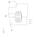
- Fig. 2 shows a further embodiment of the invention, in which the arrangement the heat exchanger 10, 20 of the cooling device or the engraving system is similar to that of FIG. 1.
- cooling circuits 40 in the form of Fig. 2 symbolically shown coils used to achieve a cooling effect are flooded with water.
- the water picks up similar to the first Embodiment of the ambient air in the heat exchanger 20 in the area heat or thermal energy from the engraving head flows in the cooling circuit 40 continues in one direction and releases to the ambient air in the heat exchanger 10 heat or thermal energy.
- the heat exchanger 10 is here from Air flows through and is therefore air-cooled, as indicated by the directional arrows in Fig. 2 is indicated.
- FIG. 3 shows a further variant of the invention. Basically you can essentially the same components are used as in FIG. 2. Indeed limit the heat exchangers 10, 20 of the cooling device in FIG. 3 not on each other or are not formed in one piece. As a result, the heat exchangers 10, 20 are walled on all sides.
- the illustrated Variation represents a locally arranged one for the engraving system of an engraving device Cooling device ready, the connection of the cooling circuit 40 of the Heat exchanger 10, 20 is made by quick couplings 65.
- the quick couplings 65 comprise a feed line 50 and a return line 60 for transporting the heat transport medium in a circuit and are preferred attached to supports, each with an engraving head (not shown).
- the heat exchangers 10, 20 can be approximately Disconnect and connect maintenance work quickly and are in a variable composition usable.
- Pump 70 may be arranged to add to the cooling circuit due to the Heat effect in the heat exchanger 40 acting forces to provide further pumping power.
Landscapes
- Engineering & Computer Science (AREA)
- Manufacturing & Machinery (AREA)
- Mechanical Engineering (AREA)
- Manufacture Or Reproduction Of Printing Formes (AREA)
- Heat-Exchange Devices With Radiators And Conduit Assemblies (AREA)
Applications Claiming Priority (2)
| Application Number | Priority Date | Filing Date | Title |
|---|---|---|---|
| DE10101134 | 2001-01-12 | ||
| DE10101134A DE10101134B4 (de) | 2001-01-12 | 2001-01-12 | Graviersystem mit einer Kühlungseinrichtung zur Kühlung des Graviersystems |
Publications (1)
| Publication Number | Publication Date |
|---|---|
| EP1223033A1 true EP1223033A1 (fr) | 2002-07-17 |
Family
ID=7670325
Family Applications (1)
| Application Number | Title | Priority Date | Filing Date |
|---|---|---|---|
| EP01129804A Withdrawn EP1223033A1 (fr) | 2001-01-12 | 2001-12-14 | Dispositif de refroidissement pour un système de gravure |
Country Status (4)
| Country | Link |
|---|---|
| US (1) | US6789470B2 (fr) |
| EP (1) | EP1223033A1 (fr) |
| JP (1) | JP3759718B2 (fr) |
| DE (1) | DE10101134B4 (fr) |
Families Citing this family (3)
| Publication number | Priority date | Publication date | Assignee | Title |
|---|---|---|---|---|
| DE10260253A1 (de) † | 2002-12-20 | 2004-07-01 | Giesecke & Devrient Gmbh | Verfahren und Vorrichtung zur Herstellung von Stichtiefdruckplatten und damit hergestellte Druckplatte |
| CA2449619A1 (fr) * | 2003-01-07 | 2004-07-07 | Heidelberger Druckmaschinen Aktiengesellschaft | Dispositif de production d'une forme d'impression |
| DE10354454B4 (de) * | 2003-11-21 | 2009-11-26 | Technotrans Ag | Temperiervorrichtung für Druckmaschinen |
Citations (3)
| Publication number | Priority date | Publication date | Assignee | Title |
|---|---|---|---|---|
| EP0710550A2 (fr) * | 1994-11-04 | 1996-05-08 | Ohio Electronic Engravers, Inc. | Procédé et appareil de gravure utilisant un actionneur magnétostrictif |
| DE19754379A1 (de) * | 1997-12-09 | 1999-06-10 | Heidelberger Druckmasch Ag | Verfahren zum Betrieb eines Gravierorgans |
| DE19812786A1 (de) * | 1998-03-24 | 1999-09-30 | Fraunhofer Ges Forschung | Elektromechanische Vorrichtung zur Ausführung linearer Bewegungen |
Family Cites Families (9)
| Publication number | Priority date | Publication date | Assignee | Title |
|---|---|---|---|---|
| JPH04259552A (ja) * | 1991-02-13 | 1992-09-16 | Yoshitaka Yoshii | ゴム判の製造装置 |
| US5663802A (en) * | 1993-02-25 | 1997-09-02 | Ohio Electronic Engravers, Inc. | Method and apparatus for engraving using multiple engraving heads |
| DE4426077A1 (de) * | 1994-07-22 | 1996-01-25 | Baldwin Gegenheimer Gmbh | Druckmaschinen-Temperierungsvorrichtung |
| US5731881A (en) * | 1994-11-04 | 1998-03-24 | Ohio Electronic Engravers, Inc. | Engraving method and apparatus using cooled magnetostrictive actuator |
| US6347891B1 (en) * | 1995-04-26 | 2002-02-19 | Ohio Electronic Engravers, Inc. | Engraving system and method comprising different engraving devices |
| US5947020A (en) * | 1997-12-05 | 1999-09-07 | Ohio Electronic Engravers, Inc. | System and method for engraving a plurality of engraved areas defining different screens |
| DE19857108A1 (de) * | 1998-12-10 | 2000-06-15 | Baldwin Grafotec Gmbh | Temperiervorrichtung einer Druckmaschine |
| IT1310833B1 (it) * | 1999-09-28 | 2002-02-22 | Sergio Sighinolfi | Apparato per incidere un rullo da stampa con un raggio laser |
| US6293199B1 (en) * | 2000-07-07 | 2001-09-25 | Baldwin Graphicssystems, Inc. | Printing press circulation system |
-
2001
- 2001-01-12 DE DE10101134A patent/DE10101134B4/de not_active Expired - Fee Related
- 2001-12-14 EP EP01129804A patent/EP1223033A1/fr not_active Withdrawn
- 2001-12-19 US US10/027,428 patent/US6789470B2/en not_active Expired - Fee Related
-
2002
- 2002-01-15 JP JP2002006630A patent/JP3759718B2/ja not_active Expired - Fee Related
Patent Citations (3)
| Publication number | Priority date | Publication date | Assignee | Title |
|---|---|---|---|---|
| EP0710550A2 (fr) * | 1994-11-04 | 1996-05-08 | Ohio Electronic Engravers, Inc. | Procédé et appareil de gravure utilisant un actionneur magnétostrictif |
| DE19754379A1 (de) * | 1997-12-09 | 1999-06-10 | Heidelberger Druckmasch Ag | Verfahren zum Betrieb eines Gravierorgans |
| DE19812786A1 (de) * | 1998-03-24 | 1999-09-30 | Fraunhofer Ges Forschung | Elektromechanische Vorrichtung zur Ausführung linearer Bewegungen |
Also Published As
| Publication number | Publication date |
|---|---|
| US20020104448A1 (en) | 2002-08-08 |
| JP2002303475A (ja) | 2002-10-18 |
| DE10101134A1 (de) | 2002-07-18 |
| JP3759718B2 (ja) | 2006-03-29 |
| US6789470B2 (en) | 2004-09-14 |
| DE10101134B4 (de) | 2008-11-06 |
Similar Documents
| Publication | Publication Date | Title |
|---|---|---|
| DE4125079C2 (de) | Ölkühler für automatisches Getriebe | |
| DE69005342T2 (de) | Zwischenstruktur zur Wärmeableitung vom elektrischen Modul. | |
| DE20105487U1 (de) | Kühlgerät mit mehreren Arbeitsmodi zur Optimierung der Effektivität. | |
| DE10354454A1 (de) | Temperiervorrichtung für Druckmaschinen | |
| DE102016215851A1 (de) | Kühlvorrichtung für eine Batteriebaugruppe sowie Einheit aus einer Batteriebaugruppe und einer Kühlvorrichtung | |
| WO2009059787A2 (fr) | Système de thermorégulation pour machines à imprimer, à plusieurs niveaux de température | |
| DE112025000085T5 (de) | Wärmeableitungsvorrichtung und Kommunikationsgerät | |
| EP0927861B1 (fr) | Appareil d'accumulation de froid avec stockage de glace | |
| DE19839477B4 (de) | Vorrichtung zur Wärmeableitung in einem Kraftfahrzeug | |
| DE10101134B4 (de) | Graviersystem mit einer Kühlungseinrichtung zur Kühlung des Graviersystems | |
| DE2732879A1 (de) | Waermetauscher | |
| DE102020203216A1 (de) | Vorrichtung zur Führung eines flüssigen oder gasförmigen Mediums, Verfahren zur Herstellung einer entsprechenden Vorrichtung, Feldfacettenmodul und Projektionsbelichtungsanlage | |
| EP2201632B1 (fr) | Pile à combustible à membrane électrolytique polymère à haute température (ht-pemfc) comprenant des dispositifs pour son refroidissement | |
| DE102018210141A1 (de) | Diodenlaseranordnung und Verfahren zur Herstellung einer Diodenlaseranordnung | |
| EP3791123B1 (fr) | Système de refroidissement et procédé pour thermoréguler un centre informatique en utilisant un système de refroidissement | |
| DE3341853A1 (de) | Fluid-kuehlvorrichtung fuer klimaanlagen | |
| DE112004002404B4 (de) | Wärmetauschvorrichtung | |
| DE2839638A1 (de) | Trockenkuehlsystem fuer kraftwerkanlagen | |
| DE102019119124A1 (de) | Kombinationswärmetauscher mit einem Chiller und einem inneren Wärmetauscher sowie Kühl-Kälte-Kreislaufsystem und Kraftfahrzeug mit einem solchen | |
| DE102022004555A1 (de) | Vorrichtung zum Temperieren zweier Medien | |
| DE102016010073A1 (de) | Kühleinrichtung für ein Kraftfahrzeug | |
| DE102024127240B3 (de) | Kühlmittelkreislaufanordnung für ein Kraftfahrzeug sowie Verfahren zum Betreiben einer Kühlmittelkreislaufanordnung | |
| DE20008740U1 (de) | Heißluft-Trockeneinrichtung | |
| DE102024200256B4 (de) | Thermomanagement-System für ein Fahrzeug und Fahrzeug mit einem solchen System | |
| DE10013094A1 (de) | Temperaturregelung für eine Werkzeugmaschine |
Legal Events
| Date | Code | Title | Description |
|---|---|---|---|
| PUAI | Public reference made under article 153(3) epc to a published international application that has entered the european phase |
Free format text: ORIGINAL CODE: 0009012 |
|
| AK | Designated contracting states |
Kind code of ref document: A1 Designated state(s): AT BE CH CY DE DK ES FI FR GB GR IE IT LI LU MC NL PT SE TR |
|
| AX | Request for extension of the european patent |
Free format text: AL;LT;LV;MK;RO;SI |
|
| RAP1 | Party data changed (applicant data changed or rights of an application transferred) |
Owner name: HELL GRAVURE SYSTEMS GMBH |
|
| AKX | Designation fees paid | ||
| REG | Reference to a national code |
Ref country code: DE Ref legal event code: 8566 |
|
| STAA | Information on the status of an ep patent application or granted ep patent |
Free format text: STATUS: THE APPLICATION IS DEEMED TO BE WITHDRAWN |
|
| 18D | Application deemed to be withdrawn |
Effective date: 20030118 |