EP1223241A2 - Vorrichtung zum Beschichten von Fäden und Leitwalze dafür - Google Patents
Vorrichtung zum Beschichten von Fäden und Leitwalze dafür Download PDFInfo
- Publication number
- EP1223241A2 EP1223241A2 EP02000517A EP02000517A EP1223241A2 EP 1223241 A2 EP1223241 A2 EP 1223241A2 EP 02000517 A EP02000517 A EP 02000517A EP 02000517 A EP02000517 A EP 02000517A EP 1223241 A2 EP1223241 A2 EP 1223241A2
- Authority
- EP
- European Patent Office
- Prior art keywords
- strand
- hub
- disposed
- guide
- shoulder flange
- Prior art date
- Legal status (The legal status is an assumption and is not a legal conclusion. Google has not performed a legal analysis and makes no representation as to the accuracy of the status listed.)
- Granted
Links
Images



Classifications
-
- B—PERFORMING OPERATIONS; TRANSPORTING
- B05—SPRAYING OR ATOMISING IN GENERAL; APPLYING FLUENT MATERIALS TO SURFACES, IN GENERAL
- B05C—APPARATUS FOR APPLYING FLUENT MATERIALS TO SURFACES, IN GENERAL
- B05C13/00—Means for manipulating or holding work, e.g. for separate articles
-
- D—TEXTILES; PAPER
- D06—TREATMENT OF TEXTILES OR THE LIKE; LAUNDERING; FLEXIBLE MATERIALS NOT OTHERWISE PROVIDED FOR
- D06B—TREATING TEXTILE MATERIALS USING LIQUIDS, GASES OR VAPOURS
- D06B23/00—Component parts, details, or accessories of apparatus or machines, specially adapted for the treating of textile materials, not restricted to a particular kind of apparatus, provided for in groups D06B1/00 - D06B21/00
- D06B23/06—Guiding means for preventing filaments, yarns or threads from sticking together
-
- B—PERFORMING OPERATIONS; TRANSPORTING
- B65—CONVEYING; PACKING; STORING; HANDLING THIN OR FILAMENTARY MATERIAL
- B65H—HANDLING THIN OR FILAMENTARY MATERIAL, e.g. SHEETS, WEBS, CABLES
- B65H57/00—Guides for filamentary materials; Supports therefor
- B65H57/14—Pulleys, rollers, or rotary bars
-
- B—PERFORMING OPERATIONS; TRANSPORTING
- B65—CONVEYING; PACKING; STORING; HANDLING THIN OR FILAMENTARY MATERIAL
- B65H—HANDLING THIN OR FILAMENTARY MATERIAL, e.g. SHEETS, WEBS, CABLES
- B65H57/00—Guides for filamentary materials; Supports therefor
- B65H57/16—Guides for filamentary materials; Supports therefor formed to maintain a plurality of filaments in spaced relation
-
- D—TEXTILES; PAPER
- D06—TREATMENT OF TEXTILES OR THE LIKE; LAUNDERING; FLEXIBLE MATERIALS NOT OTHERWISE PROVIDED FOR
- D06B—TREATING TEXTILE MATERIALS USING LIQUIDS, GASES OR VAPOURS
- D06B23/00—Component parts, details, or accessories of apparatus or machines, specially adapted for the treating of textile materials, not restricted to a particular kind of apparatus, provided for in groups D06B1/00 - D06B21/00
- D06B23/02—Rollers
-
- B—PERFORMING OPERATIONS; TRANSPORTING
- B65—CONVEYING; PACKING; STORING; HANDLING THIN OR FILAMENTARY MATERIAL
- B65H—HANDLING THIN OR FILAMENTARY MATERIAL, e.g. SHEETS, WEBS, CABLES
- B65H2701/00—Handled material; Storage means
- B65H2701/30—Handled filamentary material
- B65H2701/31—Textiles threads or artificial strands of filaments
Definitions
- the invention relates generally to strand coating systems, and more particularly to variable spacing strand coating systems and guide rollers therefor.
- An object of the present invention is to provide novel strand coating systems and guide rollers therefor that overcome problems in and improve upon the prior art.
- Another object of the invention is to provide in some embodiments thereof novel strand coating systems and guide rollers therefor that are economical.
- Another object of the invention is to provide in some embodiments thereof novel strand coating systems and guide rollers therefor that are reliable.
- a further object of the invention is to provide in some embodiments thereof novel strand guide rollers that are configured specifically for a particular application.
- Another object of the invention is to provide in some embodiments thereof novel strand coating systems and modular guide rollers therefor having a plurality of spaced apart grooves for guiding corresponding strands.
- Another object of the invention is to provide in some embodiments thereof novel strand coating systems and modular guide rollers therefor that may be assembled or configured from a limited set of components to provide different strand guide spacings.
- a further object of the invention is to provide in some embodiments thereof novel strand coating systems and guide rollers therefor that may be configured from a limited set of components to accommodate different numbers of strands.
- Another object of the invention is to provide in some embodiments thereof novel strand coating systems and guide rollers therefor that are made less susceptible to misalignment by providing no more strand guide grooves than are required for an application.
- a more particular object of the invention is to provide in some embodiments thereof novel strand coating applicator guide rollers comprising a hub, a strand guide and in some embodiments a plurality of strand guides disposed in stacked relation about the hub, each of the plurality of strand guides having a groove disposed on an outer surface thereof, the grooves spaced apart along the axis of the hub.
- Another more particular object of the invention is to provide in some embodiments thereof novel strand coating apparatuses comprising a coating material dispenser with an orifice coupled to an applicator head, a strand guide roller coupled to the applicator head in spaced apart relation to the coating material dispenser, the strand guide roller having a hub and one or more strand guides disposed thereabout, the strand guides each having an annular groove disposed thereabout and located adjacent the coating material orifice.
- Yet another more particular object of the invention is to provide in some embodiments thereof novel modular strand coating applicator guide roller systems comprising a hub having an axial support opening with bearings, the hub having a radial shoulder flange, a collar removably disposed about the hub, the collar spaced axially from the shoulder flange, one or more identical annular strand guides removably disposed in stacked relation about the hub between the shoulder flange and the removable collar, each strand guide having a corresponding annular groove disposed on an outer surface thereof.
- FIG. 1 illustrates a strand coating system comprising a coating material dispenser 10 for applying coating materials, for example a hot melt adhesive or an atomized substance, onto one or more strands, identified collectively by numeral 20, moving relative thereto.
- coating materials for example a hot melt adhesive or an atomized substance
- the strands 20 may for example be elastic rubber or LYCRA materials used in the manufacture of diapers, incontinence pads and hospital garments and other articles.
- the strands may also be wire or cable, for example a fiber optic cable, or some other elongated member onto which it is desirable to deposit a coating material.
- the exemplary dispenser 10 includes a plurality of conduits 12, shown only partially and in phantom, terminating at corresponding coating material orifices arranged in a spaced apart series on a side 14 of the dispenser.
- the orifices of the exemplary dispenser each emit therefrom a corresponding coating material flow 16, which may be a substantially continuous or discrete vacillating filament or an atomized spray, toward a corresponding strand in alignment with the orifice.
- some of the orifices 13 are illustrated schematically at the origin of the corresponding flows 16 spaced apart evenly in a single row on the dispenser.
- the orifices may be recessed or protrude from the side 14 of the dispenser. In other embodiments, the spacing between adjacent orifices is not necessarily the same. Alternatively, there may be more than one row or series of orifices arranged in alignment with the direction of the strand so that more than one orifice dispenses coating material onto each strand. In other embodiments, the orifices of adjacent rows may be offset.
- Coating material dispensers suitable for use with the present invention are disclosed for example in U.S. Patent No. 5,902,540, entitled “Meltblowing Method and Apparatus” and in U.S. Patent No. 5,904,298, entitled “Improved Meltblowing Method and System", both of which are assigned commonly with the present application.
- These preferred exemplary devices are capable of producing filaments and atomized spray patterns that vacillate predominately non-parallel to the axis of the strands and provide precise control over the coating material dispensed therefrom.
- the coating material dispenser 10 dispenses substantially continuous coating material filaments 17 having a repeating, generally omega shaped pattern from the orifices thereof, only one of which is illustrated, as disclosed more fully in co-pending U.S. Application No. 09/143,883 entitled “Omega Spray Pattern And Method Therefor", which is assigned commonly with the present application and is incorporated herein by reference.
- the coating material dispenser may be a spiral spray nozzle having a single orifice that dispenses a corresponding spiral filament onto one or more strands, or alternatively some other coating material dispensing apparatus.
- the exemplary coating material dispenser 10 is coupled to or mounted on an applicator head 40, which supplies coating material and in some embodiments heated air to the coating material dispenser, for example through a nozzle module 41, as is known generally by those having ordinary skill in the art.
- strands having coating material applied thereto are adhered to or deposited on a substrate moving relative to the coating material dispenser, usually in unison with the strands.
- the coating material dispenser however may move relative to the one or more strands and any substrate.
- a strand guide having a guiding surface is preferably disposed adjacent the coating material dispenser, preferably on an upstream side thereof, to guide the strands past the coating material dispenser.
- the one or more strands are generally drawn over the guiding surface of the strand guide, which aligns the strands side by side in spaced apart relation relative to corresponding orifices of the coating material dispenser, for dispensing coating material dispensed therefrom onto the strands.
- the strand guide is a rotatable strand guide roller 50 including a plurality of spaced apart grooves 52 disposed thereabout.
- the strands are each disposed in and guided along a corresponding groove.
- the spacing of at least some of the grooves generally corresponds with the spacing of the dispenser orifices.
- the roller aligns and guides the strands adjacent a corresponding orifice of the coating material dispenser, as illustrated in FIG. 3.
- coating material from a single orifice may be applied to multiple strands.
- the strand guide is preferably coupled to the coating material dispenser, in fixed relation relative thereto.
- the coating material dispenser and strand guide are both coupled to the applicator head, thereby eliminating or at least substantially reducing any misalignment therebetween, for example misalignment caused by vibrating machinery, as frequently occurs in prior art systems having the strand guide coupled to machinery other than the coating material dispenser.
- the exemplary roller guide 50 is rotatably coupled to a roller axle or shaft 54, preferably with roller bearings.
- the exemplary roller guide 50 is retained on the roller shaft 54 by a collar 56 fastened thereto with a set screw or other fastening means.
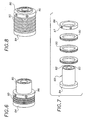
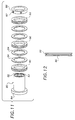
- the exemplary strand guide rollers of FIGS. 6, 8 and 10 are modular assemblies each configured differently from a limited set of components to accommodate different numbers of strands with different spacings therebetween.
- each strand guide roller is assembled about a hub 80 having an axial support opening 82 with bearings disposed thereabout, for example sealed bearings 83 located toward or at opposite ends of the axial support opening, only one of which is illustrated.
- a bushing may be a suitable equivalent for some applications.
- the hub 80 may thus be rotatably disposed about the roller shaft 54 as discussed above.
- the exemplary hub 80 also includes a shoulder flange 84 toward or at one end thereof and a removable locking collar 86 retained about the hub by a set screw 87 or other retention member toward or at an opposite end of the hub.
- the exemplary shoulder 84 is an integral part of the hub, but in alternative embodiments it may be in the form of the removable locking collar or some other discrete member assembled with the hub.
- the strand guide rollers include a plurality of at least two strand guides 90 disposed about the hub and retained in side-by-side, or stacked relation, between the shoulder 84 and locking collar 86. In other embodiments, however, the strand guide rollers may include only a single strand guide.
- the strand guide 90 is an annular member having at least one annular groove 92 disposed thereabout on an outer surface thereof.
- the strand guides 90 also have a characteristic width that determines the spacing between adjacent grooves along the axis of the hub. For example, the strand guides 90 of FIGS. 6 and 7 are more narrow than the strand guides of FIGS. 8 and 9, thereby providing a closer strand spacing in FIG. 6.
- the strand guide roller includes annular spacers 94 between the plurality of strand guides 90, thereby further separating the spacing between grooves.
- the strand guides 90 are available in several widths, for example 3 mm, 4 mm and 5 mm widths and the spacer has a 1 mm width.
- a variety of strand guide rollers having different numbers of grooves and different spacings therebetween may thus be configured with the limited number of components of the exemplary system.
- Other systems may include components having additional dimensions and/or other dimensions.
- the roller shaft 54 extends from a roller arm 58 adjustably coupled to the applicator head 40.
- the roller shaft is also preferably adjustably coupled to the roller arm, for example by threaded engagement with a threaded opening 59 of the roller arm 58.
- the roller guide 50 and/or roller shaft 54 is adjustable in either direction along the axis of the shaft 54 to align the guide grooves of the roller 50 relative to the one or more orifices of the coating material dispenser.
- the roller arm 58 is pivotally coupled to a guide arm 62 by a pivot pin 64 extending from one or the other.
- the guide arm 62 is also preferably adjustably coupled to the applicator, for example by a pivot pin 66 extending from a bracket 63 mounted thereon.
- the guide roller 50 may be adjustably positioned toward and away from a bottom side 42 the applicator head 40.
- the guide roller 50 may also be adjustably positioned in the upstream and downstream direction of the strands, closer or farther away from the dispenser.
- the roller axle 54 is secured in the opening 59 of the roller arm 58 by a bolt 60 disposed through prongs 61 thereof, which are clamped about the shaft 54 upon tightening the bolt.
- the guide arm 62 is similarly secured to the pivot pin 66, and the roller arm 58 is similarly secured to the guide arm 62.
- the guide roller is adjustably coupled to the applicator head by other structure.
- the strand guide is adjustably mounted on a pivot member to change the orientation of the guiding surface of the strand guide to vary the spacing of the strands relative to the substrate.
- the coating material dispenser is preferably adjustable in unison with the strand guide, for example by adjusting the position or orientation of the applicator head, to facilitate application of the coating material onto the strands.
- spacing between the plurality of strands 20 as they are deposited onto the substrate 30 is varied by changing the orientation of the strand guide, not illustrated, and particularly the guiding surface thereof relative to a surface 32 of the substrate.
- the plane of the strands 20 corresponds generally to the orientation of the guiding surface of the strand guide relative to the substrate surface 32.
- the grooved guiding surface of the strand guide 50 is parallel to the substrate surface 32, so that the plane of the strands 20 is also parallel to the substrate, as illustrated best in FIG. 3.
- the spacing between adjacent strands relative to the substrate surface 32 thus corresponds generally with the spacing between the grooves on the strand guide over which the strands are drawn. In FIG. 3, for example the spacing between the outermost strands is D1.
- the strand guide has been pivoted to orient the grooved guiding surface thereof at an angle relative to the substrate so that the plane of the strands is at a corresponding angle relative to the substrate.
- the spacing between adjacent strands relative to the substrate surface 32 is thus reduced in some proportion to the angle between the substrate and the guiding surface of the strand guide over which the strands are drawn.
- the spacing between the outermost strands disposed over an angled strand guide is D2, which is less than the spacing D1 in FIG. 3.
- FIGS. 1 and 2 illustrate the applicator head 40 pivotally mounted on a pivot or bolt shaft 70 having an axis substantially transverse to the side by side arrangement of the plurality of orifices, which permits adjustment of the orientation of the coating material dispenser and strands, as illustrated in FIGS. 3 and 4.
- the pivot axis of the coating material dispenser and strand guide is aligned substantially in a direction of the moving substrate, which moves into or out of the page of the drawing.
- the pivot shaft 70 extends through a mounting block 72 supported by a support member 74, in the exemplary form of a rod.
- the mounting block 72 includes one or more arcuate slots 76 disposed about the pivot shaft 70.
- a bolt 77 extends through the corresponding slot 76 and into a threaded bore of the applicator head 40.
Landscapes
- Engineering & Computer Science (AREA)
- Textile Engineering (AREA)
- Coating Apparatus (AREA)
- Application Of Or Painting With Fluid Materials (AREA)
- Rolls And Other Rotary Bodies (AREA)
- Yarns And Mechanical Finishing Of Yarns Or Ropes (AREA)
- Guides For Winding Or Rewinding, Or Guides For Filamentary Materials (AREA)
- Treatment Of Fiber Materials (AREA)
- Processes Specially Adapted For Manufacturing Cables (AREA)
- Catching Or Destruction (AREA)
- Unwinding Of Filamentary Materials (AREA)
- Conveying And Assembling Of Building Elements In Situ (AREA)
- Spinning Or Twisting Of Yarns (AREA)
- Surface Treatment Of Glass Fibres Or Filaments (AREA)
Applications Claiming Priority (2)
| Application Number | Priority Date | Filing Date | Title |
|---|---|---|---|
| US09/758,702 US6613146B2 (en) | 2001-01-11 | 2001-01-11 | Variable spacing strand coating system and modular guide roller therefor |
| US758702 | 2001-01-11 |
Publications (3)
| Publication Number | Publication Date |
|---|---|
| EP1223241A2 true EP1223241A2 (de) | 2002-07-17 |
| EP1223241A3 EP1223241A3 (de) | 2004-05-26 |
| EP1223241B1 EP1223241B1 (de) | 2008-03-12 |
Family
ID=25052751
Family Applications (1)
| Application Number | Title | Priority Date | Filing Date |
|---|---|---|---|
| EP02000517A Expired - Lifetime EP1223241B1 (de) | 2001-01-11 | 2002-01-09 | Vorrichtung zum Beschichten von Fäden und Leitwalze dafür |
Country Status (14)
| Country | Link |
|---|---|
| US (1) | US6613146B2 (de) |
| EP (1) | EP1223241B1 (de) |
| JP (1) | JP2002249282A (de) |
| KR (1) | KR100812673B1 (de) |
| CN (1) | CN1152751C (de) |
| AT (1) | ATE389049T1 (de) |
| AU (1) | AU755868B2 (de) |
| BR (1) | BR0106124A (de) |
| CA (1) | CA2365049C (de) |
| DE (1) | DE60225495T2 (de) |
| HK (1) | HK1047146A1 (de) |
| MX (1) | MXPA01013141A (de) |
| NO (1) | NO20020114L (de) |
| TW (1) | TW512125B (de) |
Cited By (1)
| Publication number | Priority date | Publication date | Assignee | Title |
|---|---|---|---|---|
| EP1243347A3 (de) * | 2001-03-23 | 2004-05-26 | Nordson Corporation | Führungssystem zum Positionieren von langgestrecktem Strang in der Umgebung eines Flüssigkeitsverteilers |
Families Citing this family (39)
| Publication number | Priority date | Publication date | Assignee | Title |
|---|---|---|---|---|
| US7462240B2 (en) * | 2003-01-24 | 2008-12-09 | Nordson Corporation | Module, nozzle and method for dispensing controlled patterns of liquid material |
| JP2007519016A (ja) | 2003-07-08 | 2007-07-12 | コーニンクレッカ フィリップス エレクトロニクス エヌ ヴィ | 可変焦点眼鏡 |
| US7485187B2 (en) * | 2003-07-18 | 2009-02-03 | Illinois Tool Works Inc. | Strand orientation alignment in strand coating systems and methods |
| US7067009B2 (en) * | 2004-06-09 | 2006-06-27 | Illinois Tool Works Inc. | Strand guide implements or mechanisms for use in connection with material dispensing and coating nozzles |
| US8277430B2 (en) | 2004-12-28 | 2012-10-02 | Kimberly-Clarl Worldwide, Inc. | Absorbent garment with strand coated adhesive components |
| US8033243B2 (en) * | 2007-06-29 | 2011-10-11 | Illinois Tool Works Inc. | Strand positioning guide having reversely oriented V-shaped slots for use in connection with strand coating applicators |
| MX2011000634A (es) * | 2010-01-18 | 2011-11-04 | Basf Se | Conjunto de guia de hebra y metodo para controlar un flujo de termoplastico fundido. |
| US8961720B2 (en) * | 2012-11-26 | 2015-02-24 | Nordson Corporation | Method for guiding and bonding strands to a substrate |
| US9820894B2 (en) | 2013-03-22 | 2017-11-21 | The Procter & Gamble Company | Disposable absorbent articles |
| US10487199B2 (en) | 2014-06-26 | 2019-11-26 | The Procter & Gamble Company | Activated films having low sound pressure levels |
| RU2017102242A (ru) | 2014-08-27 | 2018-09-27 | Дзе Проктер Энд Гэмбл Компани | Абсорбирующие трусы, характеризующиеся эффективным изготовлением и эстетичным профилем заднего края ножного отверстия |
| JP2017538536A (ja) | 2014-12-25 | 2017-12-28 | ザ プロクター アンド ギャンブル カンパニー | 弾性ベルトを有する吸収性物品 |
| US10070997B2 (en) | 2015-01-16 | 2018-09-11 | The Procter & Gamble Company | Absorbent pant with advantageously channeled absorbent core structure and bulge-reducing features |
| US10376428B2 (en) | 2015-01-16 | 2019-08-13 | The Procter & Gamble Company | Absorbent pant with advantageously channeled absorbent core structure and bulge-reducing features |
| CN106475259A (zh) * | 2015-08-24 | 2017-03-08 | 吴娟香 | 一种电缆上料箱 |
| CN106540828A (zh) * | 2015-09-17 | 2017-03-29 | 李天天 | 一种喷涂装置 |
| CN105810367A (zh) * | 2016-03-18 | 2016-07-27 | 广东中天科技光缆有限公司 | 一种用于通信电缆的缆膏涂覆机 |
| CN105858341B (zh) * | 2016-05-12 | 2019-06-14 | 新泰市铜材厂 | 一种铜丝落线顶角机构及具有该机构的收线装置 |
| EP3747414B1 (de) | 2016-08-12 | 2024-12-11 | The Procter & Gamble Company | Verfahren und vorrichtung zur anordnung von absorbierenden artikeln |
| EP3528760B1 (de) | 2016-10-18 | 2024-08-07 | Kimberly-Clark Worldwide, Inc. | Elastifizierte saugfähige artikel und verfahren zur schwächung elastischer teile bei elastifizierten saugfähigen artikeln |
| US10828208B2 (en) | 2016-11-21 | 2020-11-10 | The Procte & Gamble Company | Low-bulk, close-fitting, high-capacity disposable absorbent pant |
| US11399986B2 (en) | 2016-12-16 | 2022-08-02 | The Procter & Gamble Company | Article comprising energy curable ink |
| US10898393B2 (en) | 2016-12-19 | 2021-01-26 | The Procter & Gamble Company | Absorbent article with absorbent core |
| CN106540852A (zh) * | 2017-01-10 | 2017-03-29 | 依合斯工程塑胶(上海)有限公司 | 一种轮毂辊胶装置 |
| US20180333310A1 (en) | 2017-05-18 | 2018-11-22 | The Procter & Gamble Company | Incontinence pant with low-profile unelasticized zones |
| DE202017005954U1 (de) | 2017-10-20 | 2018-03-15 | The Procter & Gamble Company | Absorptionsartikel mit Kanälen |
| DE202017005950U1 (de) | 2017-10-25 | 2018-03-01 | The Procter & Gamble Company | Absorptionsartikel mit Kanälen |
| DE202017005956U1 (de) | 2017-10-25 | 2018-02-22 | The Procter & Gamble Company | Absorptionsartikel mit Kanälen |
| DE202017005952U1 (de) | 2017-10-25 | 2018-02-22 | The Procter & Gamble Company | Absorptionsartikel mit Kanälen |
| EP3784188B1 (de) | 2018-04-24 | 2023-11-08 | The Procter & Gamble Company | Absorbierendes höschen mit einem absorbierenden kern mit kontinuierlichem kanal |
| US20200197240A1 (en) | 2018-12-19 | 2020-06-25 | The Procter & Gamble Company | Absorbent article comprising printed region |
| US11944522B2 (en) | 2019-07-01 | 2024-04-02 | The Procter & Gamble Company | Absorbent article with ear portion |
| CN111350037B (zh) * | 2020-04-15 | 2023-11-14 | 江苏鸿展新材料科技有限公司 | 一种纤丝涂覆装置及涂覆工艺 |
| EP3906908A1 (de) | 2020-05-07 | 2021-11-10 | Ontex BV | Absorbierende artikel mit integrierter dehnungsüberwachung |
| EP3906905A1 (de) | 2020-05-07 | 2021-11-10 | Ontex BV | Absorbierende artikel mit integrierter exsudatüberwachung |
| US12605290B2 (en) | 2020-06-09 | 2026-04-21 | The Procter & Gamble Company | Article having a bond pattern |
| US20230097347A1 (en) | 2021-09-30 | 2023-03-30 | The Procter & Gamble Company | Absorbent article with laminate bond pattern |
| JP7836420B2 (ja) | 2022-05-20 | 2026-03-26 | ザ プロクター アンド ギャンブル カンパニー | 積層体結合パターンを有する吸収性物品 |
| US20240091073A1 (en) | 2022-09-08 | 2024-03-21 | The Procter & Gamble Company | Disposable absorbent pants with elasticized waist panel structure and obscuring print patterns |
Family Cites Families (19)
| Publication number | Priority date | Publication date | Assignee | Title |
|---|---|---|---|---|
| US3125126A (en) * | 1964-03-17 | Engels | ||
| BE423096A (de) * | 1936-08-13 | |||
| US2704794A (en) * | 1952-05-23 | 1955-03-22 | Western Electric Co | Capstans for advancing a plurality of strands |
| US2841020A (en) * | 1954-01-05 | 1958-07-01 | Iv Christopher Van Deventer | Sheave assemblies for looms |
| US2882214A (en) * | 1955-09-22 | 1959-04-14 | Westinghouse Electric Corp | Contact pulley assembly for wire plating apparatus |
| GB986758A (en) * | 1962-11-08 | 1965-03-24 | Ashworth Engineers Ltd J | Improved thread or like guide means |
| US3245624A (en) * | 1964-02-25 | 1966-04-12 | Formica Corp | Filament winding apparatus |
| JPS58180601A (ja) * | 1982-04-14 | 1983-10-22 | ユニ・チヤ−ム株式会社 | 使い捨ておむつ |
| US4540610A (en) * | 1982-09-30 | 1985-09-10 | Burlington Industries, Inc. | Hot melt size applying |
| JPS6062855A (ja) * | 1983-09-13 | 1985-04-11 | Sanyo Electric Co Ltd | コイル巻線機 |
| US4750960A (en) | 1984-09-10 | 1988-06-14 | Rensselaer Polytechnic Institute | Robotic winding system and method |
| US4704311A (en) * | 1985-12-04 | 1987-11-03 | Basf Corporation | Process for making electrically conductive textile filaments |
| US4839205A (en) * | 1987-07-27 | 1989-06-13 | Essex Group, Inc. | Heated supply sheaves for wire coating apparatus |
| US5364489A (en) * | 1989-09-27 | 1994-11-15 | Hughes Aircraft Company | Apparatus for applying adhesive to an optical fiber during winding |
| JP3198877B2 (ja) * | 1995-07-24 | 2001-08-13 | 三菱マテリアル株式会社 | 簡易クランプ式圧延ロール |
| US5766411A (en) | 1995-08-28 | 1998-06-16 | Paragon Trade Brands. Inc. | Apparatus for producing a garment with barrier device |
| US5964973A (en) | 1998-01-21 | 1999-10-12 | Kimberly-Clark Worldwide, Inc. | Method and apparatus for making an elastomeric laminate web |
| US6077375A (en) | 1998-04-15 | 2000-06-20 | Illinois Tool Works Inc. | Elastic strand coating process |
| US6520237B1 (en) * | 2000-07-24 | 2003-02-18 | Illinois Tool Works Inc | Variable spacing strand coating system and method |
-
2001
- 2001-01-11 US US09/758,702 patent/US6613146B2/en not_active Expired - Fee Related
- 2001-11-23 KR KR1020010073365A patent/KR100812673B1/ko not_active Expired - Fee Related
- 2001-11-29 TW TW090129584A patent/TW512125B/zh not_active IP Right Cessation
- 2001-12-11 AU AU97183/01A patent/AU755868B2/en not_active Ceased
- 2001-12-14 BR BR0106124-0A patent/BR0106124A/pt not_active Application Discontinuation
- 2001-12-17 CA CA002365049A patent/CA2365049C/en not_active Expired - Fee Related
- 2001-12-18 MX MXPA01013141A patent/MXPA01013141A/es active IP Right Grant
- 2001-12-30 CN CNB011451386A patent/CN1152751C/zh not_active Expired - Fee Related
-
2002
- 2002-01-09 AT AT02000517T patent/ATE389049T1/de not_active IP Right Cessation
- 2002-01-09 DE DE60225495T patent/DE60225495T2/de not_active Expired - Lifetime
- 2002-01-09 EP EP02000517A patent/EP1223241B1/de not_active Expired - Lifetime
- 2002-01-10 NO NO20020114A patent/NO20020114L/no not_active Application Discontinuation
- 2002-01-10 JP JP2002003462A patent/JP2002249282A/ja active Pending
- 2002-10-25 HK HK02107765.6A patent/HK1047146A1/en unknown
Cited By (1)
| Publication number | Priority date | Publication date | Assignee | Title |
|---|---|---|---|---|
| EP1243347A3 (de) * | 2001-03-23 | 2004-05-26 | Nordson Corporation | Führungssystem zum Positionieren von langgestrecktem Strang in der Umgebung eines Flüssigkeitsverteilers |
Also Published As
| Publication number | Publication date |
|---|---|
| KR20020060566A (ko) | 2002-07-18 |
| US6613146B2 (en) | 2003-09-02 |
| BR0106124A (pt) | 2002-09-10 |
| JP2002249282A (ja) | 2002-09-03 |
| AU9718301A (en) | 2002-07-18 |
| NO20020114D0 (no) | 2002-01-10 |
| CA2365049A1 (en) | 2002-07-11 |
| KR100812673B1 (ko) | 2008-03-13 |
| MXPA01013141A (es) | 2004-05-21 |
| HK1047146A1 (en) | 2003-02-07 |
| US20020088392A1 (en) | 2002-07-11 |
| TW512125B (en) | 2002-12-01 |
| AU755868B2 (en) | 2003-01-02 |
| CA2365049C (en) | 2006-09-19 |
| DE60225495D1 (de) | 2008-04-24 |
| NO20020114L (no) | 2002-07-12 |
| EP1223241B1 (de) | 2008-03-12 |
| CN1152751C (zh) | 2004-06-09 |
| EP1223241A3 (de) | 2004-05-26 |
| ATE389049T1 (de) | 2008-03-15 |
| DE60225495T2 (de) | 2009-03-19 |
| CN1364662A (zh) | 2002-08-21 |
Similar Documents
| Publication | Publication Date | Title |
|---|---|---|
| US6613146B2 (en) | Variable spacing strand coating system and modular guide roller therefor | |
| EP1176232B1 (de) | Verfahren und Vorrichtung zum Beschichten von Fäden mit variablem Abstand zueinander | |
| EP2255887B1 (de) | Verfahren zur Abgabe gesteuerter Muster von Flüssigmaterial | |
| US7578882B2 (en) | Module, nozzle and method for dispensing controlled patterns of liquid material | |
| US20050013940A1 (en) | Strand orientation alignment in strand coating systems and methods | |
| WO2009005911A2 (en) | Strand positioning guide for use in connection with strand coating applications | |
| US8961720B2 (en) | Method for guiding and bonding strands to a substrate | |
| HK1081898B (en) | Module, nozzle and method for dispensing controlled patterns of liquid material |
Legal Events
| Date | Code | Title | Description |
|---|---|---|---|
| PUAI | Public reference made under article 153(3) epc to a published international application that has entered the european phase |
Free format text: ORIGINAL CODE: 0009012 |
|
| AK | Designated contracting states |
Kind code of ref document: A2 Designated state(s): AT BE CH CY DE DK ES FI FR GB GR IE IT LI LU MC NL PT SE TR |
|
| AX | Request for extension of the european patent |
Free format text: AL;LT;LV;MK;RO;SI |
|
| PUAL | Search report despatched |
Free format text: ORIGINAL CODE: 0009013 |
|
| AK | Designated contracting states |
Kind code of ref document: A3 Designated state(s): AT BE CH CY DE DK ES FI FR GB GR IE IT LI LU MC NL PT SE TR |
|
| AX | Request for extension of the european patent |
Extension state: AL LT LV MK RO SI |
|
| RIC1 | Information provided on ipc code assigned before grant |
Ipc: 7D 06B 23/02 A Ipc: 7B 05C 5/02 B Ipc: 7D 06B 23/06 B Ipc: 7B 65H 57/14 B Ipc: 7B 65H 57/16 B |
|
| 17P | Request for examination filed |
Effective date: 20040608 |
|
| AKX | Designation fees paid |
Designated state(s): AT BE CH CY DE DK ES FI FR GB GR IE IT LI LU MC NL PT SE TR |
|
| 17Q | First examination report despatched |
Effective date: 20060802 |
|
| GRAP | Despatch of communication of intention to grant a patent |
Free format text: ORIGINAL CODE: EPIDOSNIGR1 |
|
| GRAS | Grant fee paid |
Free format text: ORIGINAL CODE: EPIDOSNIGR3 |
|
| GRAA | (expected) grant |
Free format text: ORIGINAL CODE: 0009210 |
|
| AK | Designated contracting states |
Kind code of ref document: B1 Designated state(s): AT BE CH CY DE DK ES FI FR GB GR IE IT LI LU MC NL PT SE TR |
|
| REG | Reference to a national code |
Ref country code: GB Ref legal event code: FG4D |
|
| REG | Reference to a national code |
Ref country code: CH Ref legal event code: EP |
|
| REG | Reference to a national code |
Ref country code: IE Ref legal event code: FG4D |
|
| REF | Corresponds to: |
Ref document number: 60225495 Country of ref document: DE Date of ref document: 20080424 Kind code of ref document: P |
|
| REG | Reference to a national code |
Ref country code: SE Ref legal event code: TRGR |
|
| PG25 | Lapsed in a contracting state [announced via postgrant information from national office to epo] |
Ref country code: FI Free format text: LAPSE BECAUSE OF FAILURE TO SUBMIT A TRANSLATION OF THE DESCRIPTION OR TO PAY THE FEE WITHIN THE PRESCRIBED TIME-LIMIT Effective date: 20080312 |
|
| PG25 | Lapsed in a contracting state [announced via postgrant information from national office to epo] |
Ref country code: AT Free format text: LAPSE BECAUSE OF FAILURE TO SUBMIT A TRANSLATION OF THE DESCRIPTION OR TO PAY THE FEE WITHIN THE PRESCRIBED TIME-LIMIT Effective date: 20080312 |
|
| PG25 | Lapsed in a contracting state [announced via postgrant information from national office to epo] |
Ref country code: BE Free format text: LAPSE BECAUSE OF FAILURE TO SUBMIT A TRANSLATION OF THE DESCRIPTION OR TO PAY THE FEE WITHIN THE PRESCRIBED TIME-LIMIT Effective date: 20080312 |
|
| ET | Fr: translation filed | ||
| PG25 | Lapsed in a contracting state [announced via postgrant information from national office to epo] |
Ref country code: PT Free format text: LAPSE BECAUSE OF FAILURE TO SUBMIT A TRANSLATION OF THE DESCRIPTION OR TO PAY THE FEE WITHIN THE PRESCRIBED TIME-LIMIT Effective date: 20080818 Ref country code: ES Free format text: LAPSE BECAUSE OF FAILURE TO SUBMIT A TRANSLATION OF THE DESCRIPTION OR TO PAY THE FEE WITHIN THE PRESCRIBED TIME-LIMIT Effective date: 20080623 |
|
| PLBE | No opposition filed within time limit |
Free format text: ORIGINAL CODE: 0009261 |
|
| STAA | Information on the status of an ep patent application or granted ep patent |
Free format text: STATUS: NO OPPOSITION FILED WITHIN TIME LIMIT |
|
| PG25 | Lapsed in a contracting state [announced via postgrant information from national office to epo] |
Ref country code: DK Free format text: LAPSE BECAUSE OF FAILURE TO SUBMIT A TRANSLATION OF THE DESCRIPTION OR TO PAY THE FEE WITHIN THE PRESCRIBED TIME-LIMIT Effective date: 20080312 |
|
| 26N | No opposition filed |
Effective date: 20081215 |
|
| PG25 | Lapsed in a contracting state [announced via postgrant information from national office to epo] |
Ref country code: MC Free format text: LAPSE BECAUSE OF NON-PAYMENT OF DUE FEES Effective date: 20090131 |
|
| PG25 | Lapsed in a contracting state [announced via postgrant information from national office to epo] |
Ref country code: CY Free format text: LAPSE BECAUSE OF FAILURE TO SUBMIT A TRANSLATION OF THE DESCRIPTION OR TO PAY THE FEE WITHIN THE PRESCRIBED TIME-LIMIT Effective date: 20080312 |
|
| PG25 | Lapsed in a contracting state [announced via postgrant information from national office to epo] |
Ref country code: IE Free format text: LAPSE BECAUSE OF NON-PAYMENT OF DUE FEES Effective date: 20090109 |
|
| PGFP | Annual fee paid to national office [announced via postgrant information from national office to epo] |
Ref country code: CH Payment date: 20100125 Year of fee payment: 9 |
|
| PGFP | Annual fee paid to national office [announced via postgrant information from national office to epo] |
Ref country code: FR Payment date: 20100205 Year of fee payment: 9 Ref country code: IT Payment date: 20100126 Year of fee payment: 9 |
|
| PGFP | Annual fee paid to national office [announced via postgrant information from national office to epo] |
Ref country code: DE Payment date: 20100127 Year of fee payment: 9 Ref country code: GB Payment date: 20100125 Year of fee payment: 9 |
|
| PGFP | Annual fee paid to national office [announced via postgrant information from national office to epo] |
Ref country code: NL Payment date: 20100124 Year of fee payment: 9 |
|
| PG25 | Lapsed in a contracting state [announced via postgrant information from national office to epo] |
Ref country code: GR Free format text: LAPSE BECAUSE OF FAILURE TO SUBMIT A TRANSLATION OF THE DESCRIPTION OR TO PAY THE FEE WITHIN THE PRESCRIBED TIME-LIMIT Effective date: 20080613 |
|
| PGFP | Annual fee paid to national office [announced via postgrant information from national office to epo] |
Ref country code: SE Payment date: 20100127 Year of fee payment: 9 |
|
| PG25 | Lapsed in a contracting state [announced via postgrant information from national office to epo] |
Ref country code: LU Free format text: LAPSE BECAUSE OF NON-PAYMENT OF DUE FEES Effective date: 20090109 |
|
| REG | Reference to a national code |
Ref country code: NL Ref legal event code: V1 Effective date: 20110801 |
|
| REG | Reference to a national code |
Ref country code: HK Ref legal event code: WD Ref document number: 1047146 Country of ref document: HK |
|
| PG25 | Lapsed in a contracting state [announced via postgrant information from national office to epo] |
Ref country code: TR Free format text: LAPSE BECAUSE OF FAILURE TO SUBMIT A TRANSLATION OF THE DESCRIPTION OR TO PAY THE FEE WITHIN THE PRESCRIBED TIME-LIMIT Effective date: 20080312 |
|
| REG | Reference to a national code |
Ref country code: CH Ref legal event code: PL |
|
| REG | Reference to a national code |
Ref country code: SE Ref legal event code: EUG |
|
| GBPC | Gb: european patent ceased through non-payment of renewal fee |
Effective date: 20110109 |
|
| REG | Reference to a national code |
Ref country code: FR Ref legal event code: ST Effective date: 20110930 |
|
| PG25 | Lapsed in a contracting state [announced via postgrant information from national office to epo] |
Ref country code: CH Free format text: LAPSE BECAUSE OF NON-PAYMENT OF DUE FEES Effective date: 20110131 Ref country code: LI Free format text: LAPSE BECAUSE OF NON-PAYMENT OF DUE FEES Effective date: 20110131 Ref country code: FR Free format text: LAPSE BECAUSE OF NON-PAYMENT OF DUE FEES Effective date: 20110131 |
|
| PG25 | Lapsed in a contracting state [announced via postgrant information from national office to epo] |
Ref country code: GB Free format text: LAPSE BECAUSE OF NON-PAYMENT OF DUE FEES Effective date: 20110109 |
|
| REG | Reference to a national code |
Ref country code: DE Ref legal event code: R119 Ref document number: 60225495 Country of ref document: DE Effective date: 20110802 |
|
| PG25 | Lapsed in a contracting state [announced via postgrant information from national office to epo] |
Ref country code: IT Free format text: LAPSE BECAUSE OF NON-PAYMENT OF DUE FEES Effective date: 20110109 Ref country code: NL Free format text: LAPSE BECAUSE OF NON-PAYMENT OF DUE FEES Effective date: 20110801 |
|
| PG25 | Lapsed in a contracting state [announced via postgrant information from national office to epo] |
Ref country code: SE Free format text: LAPSE BECAUSE OF NON-PAYMENT OF DUE FEES Effective date: 20110110 |
|
| PG25 | Lapsed in a contracting state [announced via postgrant information from national office to epo] |
Ref country code: DE Free format text: LAPSE BECAUSE OF NON-PAYMENT OF DUE FEES Effective date: 20110802 |