EP1223290A2 - Drehtüranlage - Google Patents
Drehtüranlage Download PDFInfo
- Publication number
- EP1223290A2 EP1223290A2 EP01130802A EP01130802A EP1223290A2 EP 1223290 A2 EP1223290 A2 EP 1223290A2 EP 01130802 A EP01130802 A EP 01130802A EP 01130802 A EP01130802 A EP 01130802A EP 1223290 A2 EP1223290 A2 EP 1223290A2
- Authority
- EP
- European Patent Office
- Prior art keywords
- bearing
- wing
- axis
- revolving door
- door system
- Prior art date
- Legal status (The legal status is an assumption and is not a legal conclusion. Google has not performed a legal analysis and makes no representation as to the accuracy of the status listed.)
- Granted
Links
- 230000005540 biological transmission Effects 0.000 claims description 7
- 230000001276 controlling effect Effects 0.000 claims description 2
- 238000006073 displacement reaction Methods 0.000 claims description 2
- 230000001105 regulatory effect Effects 0.000 claims description 2
- 241000638935 Senecio crassissimus Species 0.000 claims 1
- 230000006378 damage Effects 0.000 description 9
- 208000027418 Wounds and injury Diseases 0.000 description 7
- 208000014674 injury Diseases 0.000 description 7
- 230000007774 longterm Effects 0.000 description 5
- 238000010276 construction Methods 0.000 description 4
- 230000002349 favourable effect Effects 0.000 description 4
- 238000009434 installation Methods 0.000 description 4
- 238000005553 drilling Methods 0.000 description 2
- 230000003287 optical effect Effects 0.000 description 2
- 230000000994 depressogenic effect Effects 0.000 description 1
- 230000000694 effects Effects 0.000 description 1
- 210000003746 feather Anatomy 0.000 description 1
- 230000001404 mediated effect Effects 0.000 description 1
- 230000001681 protective effect Effects 0.000 description 1
- 238000000926 separation method Methods 0.000 description 1
- 230000003068 static effect Effects 0.000 description 1
- 239000000725 suspension Substances 0.000 description 1
- 230000000007 visual effect Effects 0.000 description 1
Images


Classifications
-
- E—FIXED CONSTRUCTIONS
- E05—LOCKS; KEYS; WINDOW OR DOOR FITTINGS; SAFES
- E05D—HINGES OR SUSPENSION DEVICES FOR DOORS, WINDOWS OR WINGS
- E05D15/00—Suspension arrangements for wings
- E05D15/02—Suspension arrangements for wings for revolving wings
-
- E—FIXED CONSTRUCTIONS
- E06—DOORS, WINDOWS, SHUTTERS, OR ROLLER BLINDS IN GENERAL; LADDERS
- E06B—FIXED OR MOVABLE CLOSURES FOR OPENINGS IN BUILDINGS, VEHICLES, FENCES OR LIKE ENCLOSURES IN GENERAL, e.g. DOORS, WINDOWS, BLINDS, GATES
- E06B3/00—Window sashes, door leaves, or like elements for closing wall or like openings; Layout of fixed or moving closures, e.g. windows in wall or like openings; Features of rigidly-mounted outer frames relating to the mounting of wing frames
- E06B3/90—Revolving doors; Cages or housings therefor
-
- E—FIXED CONSTRUCTIONS
- E05—LOCKS; KEYS; WINDOW OR DOOR FITTINGS; SAFES
- E05F—DEVICES FOR MOVING WINGS INTO OPEN OR CLOSED POSITION; CHECKS FOR WINGS; WING FITTINGS NOT OTHERWISE PROVIDED FOR, CONCERNED WITH THE FUNCTIONING OF THE WING
- E05F15/00—Power-operated mechanisms for wings
- E05F15/60—Power-operated mechanisms for wings using electrical actuators
- E05F15/603—Power-operated mechanisms for wings using electrical actuators using rotary electromotors
- E05F15/608—Power-operated mechanisms for wings using electrical actuators using rotary electromotors for revolving wings
-
- E—FIXED CONSTRUCTIONS
- E05—LOCKS; KEYS; WINDOW OR DOOR FITTINGS; SAFES
- E05Y—INDEXING SCHEME ASSOCIATED WITH SUBCLASSES E05D AND E05F, RELATING TO CONSTRUCTION ELEMENTS, ELECTRIC CONTROL, POWER SUPPLY, POWER SIGNAL OR TRANSMISSION, USER INTERFACES, MOUNTING OR COUPLING, DETAILS, ACCESSORIES, AUXILIARY OPERATIONS NOT OTHERWISE PROVIDED FOR, APPLICATION THEREOF
- E05Y2201/00—Constructional elements; Accessories therefor
- E05Y2201/20—Brakes; Disengaging means; Holders; Stops; Valves; Accessories therefor
- E05Y2201/21—Brakes
-
- E—FIXED CONSTRUCTIONS
- E05—LOCKS; KEYS; WINDOW OR DOOR FITTINGS; SAFES
- E05Y—INDEXING SCHEME ASSOCIATED WITH SUBCLASSES E05D AND E05F, RELATING TO CONSTRUCTION ELEMENTS, ELECTRIC CONTROL, POWER SUPPLY, POWER SIGNAL OR TRANSMISSION, USER INTERFACES, MOUNTING OR COUPLING, DETAILS, ACCESSORIES, AUXILIARY OPERATIONS NOT OTHERWISE PROVIDED FOR, APPLICATION THEREOF
- E05Y2900/00—Application of doors, windows, wings or fittings thereof
- E05Y2900/10—Application of doors, windows, wings or fittings thereof for buildings or parts thereof
- E05Y2900/13—Type of wing
- E05Y2900/132—Doors
Definitions
- the invention relates to a revolving door system with an intermediate cylindrical segment-shaped boundary walls that opposite sides each have a passage area have taken up and around a vertical door rotation axis, preferably by means of a drive rotatable multi-wing Revolving door, the wing of which is close to the boundary walls reach up and at least one wing from them a vertical wing axis from a basic position in which the wings are preferably at equal angular distances extend from the door axis of rotation into one of the essentially Opening position allowing unhindered passage of people is pivotable.
- Such a revolving door system is known from EP 0 606 193 A1 known.
- the leaves are one multi-leaf swing door, which in turn by means of a drive motor is driven to rotate about an axis in order Area of the up to cylindrical segment-shaped boundary walls vertical articulation axes arranged reaching wing ends from a basic position, which is a controlled passage of people allows to release in a wide passage Open positions and from the latter back to their basic positionstechnischverschwenkbar.
- the swinging of the wings in their opening positions and back can be done by hand or also by means of motorized drives respectively.
- the swing door drive is controlled so that For example, with four-leaf revolving doors, the leaves with their ends distant from the revolving door axis of rotation at a standstill the revolving door near the boundary walls breakthrough passage areas.
- Such revolving doors with from their basic positions in opening positions hinged wings allow opening wide passages. This is with a large number of visitors or also useful for pushing through larger items. Such wide passages also come in particular as an escape route meaning too.
- the wing is expediently on a door axis of rotation containing and arranged coaxially to this bearing shaft stored. This enables long-term stable storage of the wing as well as simple assembly and disassembly conditions.
- the wing is stored in this way is that its weight is essentially one in the range the lower end of the bearing shaft arranged bearings added is. This allows unfavorable tipping conditions avoid and stable storage can be achieved.
- the hinged wing is advantageously with at least a bearing element which can be linked to the bearing shaft, the shaft bearing part assigned to the bearing shaft and comprises a wing bearing part assigned to the wing, wherein the shaft bearing part the bearing shaft at least partially included and preferably pioneering has parallel bearing surfaces for absorbing vertical forces, the wing bearing part by a parallel to the Bearing element axis arranged pivotally on bearing surfaces the shaft bearing part is articulated.
- This construction has Large ones in particular for large and / or heavy sashes
- Advantages because even with inaccurately aligned wing bearing parts always by the weight of the heavy wings conditional vertical forces over a large area and evenly the bearing surfaces of the shaft bearing parts are included can, which is preferably more suitable with the interposition Support the axial slide bearing on each other.
- wing bearing part and Shaft bearing part are releasably connected to one another easy assembly and disassembly of the wings on the bearing shaft to enable.
- a detachable connection for example two fitting bolts provided with an internal thread the correspondingly designed mounting holes can be used appropriately and by means of a suitable Aid device again from the fitting holes can be removed.
- the wing bearing part as a bearing fork and the shaft bearing part designed as a fork mount
- the storage fork includes the fork holder with its two fork legs, which can be pivoted about the bearing element axis on the fork mount are articulated.
- the vertical bearing shaft in the area of its lower end a camp stored so that they tilt-wobble movements relative to a vertical axis containing a fulcrum can run around that pivot point. That way a degree of freedom in the vertical direction is advantageous create, so that by this oscillating storage changing temperatures none due to different thermal expansion conditional difficulties, such as a stiff or jammed revolving door occur.
- the bearing shaft is expediently in the region of its lower one Endes and / or the wings on a spherical roller bearing stored.
- a preferred alternative embodiment has the bearing for the bearing shaft and / or that Bear a spherical bearing head for the wings, which is stored in a storage pan.
- This allows a particularly robust and inexpensive as well as a long one Create life bearing, with a simple Assembly and disassembly are possible.
- bearing pan is preferred recorded on or in a tapered roller bearing is.
- the wings and the bearing shaft on a common bearing stored so that the weight of the wing and the bearing shaft as well as the drive and the brake unit from a single one Camp is added.
- the bearing shaft in the area of its upper end detachable with a preferably designed as a hollow shaft gear output shaft of a gear motor connected and arranged coaxially to this.
- the bearing shaft is advantageously in the area of its upper one In the end, preferably releasably mounted on a support bearing, that over at least two, preferably three torque arms supported on a body of the revolving door system, each torque arm with adjustment means for adjustment the position of the support bearing and consequently the bearing shaft is provided relative to the body. That way the revolving door can be adjusted exactly to a constant Distance between the wings and the boundary walls make sure.
- the rotating element supports advantageously have one with a counter-rotating thread Adjustment element on that with a matching thread provided second adjusting element cooperates in such a way that with a rotation of the with the opposite thread provided first adjustment element a transverse Displacement of the first adjusting element relative to that second adjustment element is effected.
- the wings are advantageously by means of an output shaft having drive can be pivoted about the door axis of rotation, the output shaft with a cam can be coupled, which can be brought into operative connection with the wings is. It is useful if the cam fixed, preferably releasable with the output shaft of the Geared motor designed drive is connected.
- first locking element part with a U- or V-shaped, radially projecting guide flanks having recess and the second locking element part with a radially engaging in the recess and resiliently resettable from the guide flanks Pressure element are designed, preferably the latter Contact pressure is infinitely adjustable.
- the second locking element part is designed with a gas pressure spring attached to your the Recess of the first locking element part associated free End has a cam roller formed guide roller, on the leading edges of the recesses and intermediate ones Guide surfaces of the cam can be guided along is. This enables favorable pressing and guiding conditions and allows fine adjustment of the pressing force and consequently the restoring force.
- each locking bolt with the cam is connected and to the respective wing can be brought into locking engagement in such a way that pivoting of the wing about its wing axis to a predetermined Angular range is limited, and the locking bolt when a certain event occurs, such as a power failure or power cut, the wing releases so that this is freely pivotable about its wing axes. On this way the door can be used for escape and escape routes become.
- each folding wing a firmly connected to it in the area of its upper end Has bolt receptacle, which is a predetermined Angle extending around the respective wing axis Has recess for receiving the locking bolt.
- the Lock bolt in a driving position in which the drive the wing over the mutually engaging Locking element parts takes place relatively in a basic position to the recess extending on both sides, from which a swinging of the wing on both sides around the wing axis possible by a certain swivel angle is, preferably the pivot angle about plus / minus 10 degrees.
- a locking bolt is provided, which in the case of a specific Event, such as power failure or power cut, engages in the orbit of the wing and that on this Swing the wings around their wing axes in a circumferential angle of the associated boundary wall appropriate coverage area and this there are prevented from further pivoting.
- a preferably electromagnetic Brake can be coupled with a preferably annular brake disc is formed.
- the Brake disc expediently concentric to the door axis of rotation arranged, the disc plane normal to that Door axis of rotation is formed.
- each wing with at least one sensor for controlling or regulating the Rotation of the leaves around the door rotation axis or the leaf axis.
- sensors come in particular Impact protection sensors in question, being a first impact sensor can be provided in the form of a heel bar and wherein a second, optical, preferably IR sensor which is placed in the area of the upper end of each wing can be a visual control of the direction of rotation the rotating door leaf allows room.
- slip ring arrangements arranged concentrically to the door axis of rotation or the leaf axis Slip rings with the control device connected. It is also useful if a first slip ring arrangement at the upper end of the bearing shaft with several spaced apart in the direction of the door axis of rotation and arranged around the circumference of the door axis of rotation Slip rings, preferably as an encapsulated slip ring box is provided, and that one between the first slip ring assembly and the transmission output shaft arranged second slip ring arrangement with a plurality of concentrically spaced in a normal to the door axis of rotation or the leaf axis trained level spaced from each other Slip rings, preferably as a slip ring arrangement is designed. In this way, the revolving door can be rotated as desired without the risk of being twisted or sheared cables.
- the ones described above Slip ring arrangements mean an advantageous saving of space and enable easy assembly and disassembly.
- Very particularly advantageous assembly and disassembly conditions can also be achieved if the drive that Brake and preferably the cam a common, with the bearing shaft fixed, but releasably connectable unit form.
- This unit can be conveniently Pre-assemble the manufacturer and can then work on the actual one Installation site in a simple manner on the body of the Swing door system put on and there with the remaining parts of the revolving door system.
- every single foldable wing is separate, preferably independent of the other wings by one vertical arranged coaxially to the door axis of rotation Wing axis swiveling.
- the revolving door system 20 shown in FIGS. 1, 2, 12 and 13 comprises the frame-like body 95, which with the two lateral, cylindrical segment-shaped boundary walls 21, 22 is designed.
- the boundary walls 21, 22 have a passage area on opposite sides 23, 24.
- rotatable multi-leaf revolving door 27 added in the body 95 of the revolving door system 20 that about the vertical door axis of rotation 25 by means of the drive 26 rotatable multi-leaf revolving door 27 added.
- the revolving door 27 has the four wings 31, 32 in the exemplary embodiment, 33, 34 on the one containing the door axis of rotation 25 Bearing shaft 40 are articulated. It is understood that the Revolving door system 20 also with two, three or four to 8 or even more wings can be provided.
- 1 and 2 apparent basic position 36 extend the Wing 31, 32, 33, 34 of the door axis of rotation 25 with here in each case equal angular distances (here 90 degrees) between the individual wings 31, 32, 33, 34 on.
- this basic position 36 is a normal operation of the revolving door system 20 as Revolving door for individual separation and / or counting, So possible for a controlled passage of people.
- the transport of bulky goods and / or larger stocks through the revolving door system 20 can the wings 31, 32, 33, 34 about their vertical wing axis 35 pivoted from the basic position 36 into an open position 37 (Fig. 13).
- the wing axes 35th the wing 31, 32 33, 34 coaxial with the door axis of rotation 25 trained i.e. coincide with this, remains even when the wings 31, 32, 33, 34 are folded down into one essentially allowing unhindered passage of people Open position 37 the distance between the vertical Front edges of the wings 31, 32, 33, 34 and the vertical Boundary walls 21, 22 always the same size. This leaves yourself when folding one, several or each of the wings 31, 32, 33, 34 in his or her opening position a risk of injury exclude or minimize.
- the bearing shaft 40 rotatably mounted.
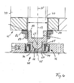
- the bearing 41 can be according to a first alternative embodiment with a spherical roller bearing 64 can be designed as shown in FIG. 3.
- the bearing sleeve 88 has from the spherical roller bearing 64, normal to the door axis of rotation 25 arranged storage areas on which a as Axial sliding ring designed sliding ring 84 is mounted. On the bottom of the slide ring 84 is supported by four Storage and support of the wing 31, 32, 33, 34 serving Bearing element 45 from.
- the bearing 41 with a ball head Bearing head 65 formed with a spherical cap 66.
- the bearing head 65 is received in a bearing pan 67 and is in the embodiment in one piece with one Receiving sleeve 83 provided for receiving the lower End 63 of the bearing shaft 40 is used.
- the receiving sleeve 83 is provided with an external thread, on which they fit with a threaded sleeve 87 is screwed on. This is also pointing away from the bearing head 65 Designed storage areas on which the bearing sleeve 86 is recorded, which with mutually pointing parallel, Bearing surfaces designed normal to the door axis of rotation 25 is designed.
- a sliding ring 84 is arranged on the bearing surface the bottom of the four for storage and support of the Wing 31, 32, 33, 34 serving bearing element 45 supports.
- the bearing head 65 comprises the spherical cap 66, which with the Sphere center 68 arranged spherical surface parts.
- the ball center 68 coincides with the door axis of rotation 25.
- the bearing pan 67 is a receptacle for the Bearing head 65 designed. For this, they are conical in Direction of the vertical central axis 69 in one of the Bearing head 65 pioneering direction tapered wall parts 70, 71 provided to support the spherical cap 66 serve. In this way, the bearing shaft 40 is more precise Position stably stored.
- the bearing pan 67 is also with from the wall parts 70, 71 in the direction of the central axis 69 extending wall parts formed, which is a cylindrical Allow inclusion of the bearing head 65 with little play.
- the bearing pan 67 is based on an inner ring of a tapered roller bearing 76 from, which in turn is on the tapered rollers on an outer ring supports, which in turn is included in a warehouse is.
- this serves both for mounting the wings 31, 32, 33, 34 and also for mounting the bearing shaft 40, both the weight of the wings 31, 32, 33, 34 and the weight of the bearing shaft 40 from the one, common Bearing 41 is added.
- the bearing shaft 40 is lower end 63 mounted on the bearing 41 so that it Tilt-tumble movements relative to a pivot point containing vertical axis, here the central axis 69, um can execute this pivot.
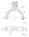
- Each wing 31, 32, 33, 34 is with a lower bearing element 42, 43, 44, 45 and an upper bearing element 72, 73, 74, 75 provided, each one end firmly with the respective Leaf 31, 32, 33, 34 in the area of the door axis of rotation 25 facing end is attached and each on the other hand are articulated on the bearing shaft 40.
- Each bearing element 42, 43, 44, 45; 72, 73, 74, 75 is with the fork seat 46, also referred to as the shaft bearing part and the bearing fork 50, also referred to as a wing bearing part designed (Fig. 5 to 9).
- the fork contains the steerer tube 60, which is in the two fork legs 51 and 52 branched.
- the fork seat 46 also referred to as the shaft bearing part, that is assigned to the bearing shaft 40 is disk-shaped formed and has the two parallel bearing surfaces 47th and 48 on that normal to the central axis of the bearing shaft 40 receiving cylinder bore 49 are arranged. At least one of the bearing surfaces 47, 48, here the bearing surface 47 is slight compared to the surface of the fork seat deepened and circular in this area designed. In the thus formed, a centering The slide ring can enable the groove to be turned out (Fig. 3, Fig. 4) can be safely recorded. These Perma slip rings 84 serve to minimize wear and tear allow a defined torque.
- the fork mount 46 is in the form of a segment of a circle in the plan view according to FIG.
- bearing elements 42, 43, 44, 45; 72, 73, 74, 75 will even with a slightly tilted in the vertical direction
- Mounting the bearing elements on the respective wing 31, 32, 33, 34 ensured that due to the possibility of pivoting the fork receptacle 46 relative to the bearing fork 50 around the bearing element axis 53, always in the entire area of Bearing surfaces 47, 48 a constant large area recording that caused by the weight of the wings 31, 32, 33, 34 Vertical forces is guaranteed.
- bearing elements 42, 43, 44, 45; 72, 73, 74, 75 is an inexpensive pre-assembly of the entire revolving door system 20 including that through the cylinder bore 49 of the Shaft bearing part 46 possible bearing shaft 40 inserted, the wings 31, 32, 33, 34 with their bearing forks 50 in the associated fork receptacle 46, for example with the help of the fitting bolts 28, can be pivotally attached.
- the Bearing shaft 40 is detachable in the area of its upper end 61 with the transmission output shaft designed here as a hollow shaft 80 of the gear motor 85 connected and coaxial with this arranged.
- the gear motor is in turn on the body 95 the revolving door system 20 on the crossbar shown in FIG. 12 96 attached.
- This crossbar 96 is about the arranged in a normal to the door axis of rotation 25 or hollow shaft 80
- Torque supports 91, 92, 93 supported and supported.
- the torque supports 91, 92, 93 are in turn on the frame-like body 95 of the revolving door system 20 attached.
- the torque supports 91, 92, 93 connected in an articulated manner to the body 95 at one end and articulated at its other end with crossbeams 96 connected.
- the torque arms 91, 92, 93 are with the Adjustment means 97, 98, 99 designed, each with opposing threaded sockets and between these connected with the sleeves, also with opposing ones Threaded threaded rods are formed.
- Threaded threaded rods By rotating the threaded rods or the threaded sleeves the respective distance between the ends of the torque arms 91, 92, 93 can be varied.
- the location of the also called support bearing and as Transmission output shaft acting hollow shaft 80 and consequently the position of the bearing shaft 40 and that with the Swing door 27 provided with wings 31, 32, 33, 34 relative to the Body 95, in particular relative to the boundary walls 21 and 22 can be set exactly.
- the bearing shaft 41 stored at its lower end 63 on the bearing 41 and is in the area of its upper end 61 on the transmission output shaft of the gear motor 85 mounted. It is on the upper end 61 of the bearing shaft 40 a disc-shaped Flange 62 is provided, which is welded to the bearing shaft 40 is and again in the embodiment detachable screw connection with an opposite also disc-shaped flange 77 can be connected, the is welded to the output shaft 55.
- the output shaft 55 is at its, from the upper end 61 of the bearing shaft 40th technological end, provided with a groove 82 and also the Hollow shaft 80 is provided with a corresponding groove, so that the output shaft 55 on the suitably received in the grooves Spring 81 rotatably and operatively connected to the hollow shaft 80 is.
- the cam disk 100 designed for the door axis of rotation 25, those running in a normal to the door axis of rotation 25 Level is arranged.
- the cam 100 rotates consequently, like the bearing shaft 40, with a rotary drive the hollow shaft 80 by the gear motor 85, preferably in the direction of rotation 135 shown in FIG. How 12, the cam 100 is along their circumference according to the number of four wings 31, 32, 33, 34 with those also referred to as first locking element part 101 U or V-shaped recesses 105 are provided, which here at equal angular intervals of 90 degrees above the Scope of the cam 100 are arranged distributed.
- This Recesses 105 serve as locking points for fixing the basic position 36, in which the wings 31, 32, 33, 34 from the door axis of rotation 25, here at equal angular distances, continue in the direction of the boundary walls 21 and 22.
- the gas pressure spring 107 In the basic position 36 engage in the recesses 105 which are also referred to as second locking element parts 102 Guide rollers 110 attached to the free end 108 the gas pressure spring 107 are arranged and fixed to the respective door leaf 31, 32, 33, 34, here on the upper horizontal front edge are attached.
- the adjustable Gas spring 107 can the pressing force of the referred to as pressure element 106 guide rollers 110 the outer circumference of the cam discs 100 can be set.
- the pressing force of the guide roller 110 on the cam 100 is set such that for the normal case the operation of the revolving door system as by the drive 26 Revolving revolving door driven by a drive 26 caused rotation of the cam, the wings 31, 32, 33, 34 are rotated, so that consequently in this operating state forming the guide rollers 110 with the locking points Recesses 105 of the cam are engaged.
- Locking latch devices 121 attached, accordingly the number of four provided in the exemplary embodiment Wing 31, 32, 33, 34 also four locking latch devices are provided.
- the locking bolt device 121 serves for actuating one with the respective wing 31, 32, 33, 34 engageable locking bolt 120.
- the Locking bolt 120 in the basic position shown in FIG. 9 128, which corresponds to the driving position 127, in a Recess 126 of a locking plate designed as a locking receptacle 125, which at the upper end 38 of each wing 31, 32, 33, 34 and fastened here on the front upper edge of the wing is.
- the locking latch device 121 is electrical controllable so that in the current-carrying state or at Application of an electrical voltage, the locking bolt 120 against the spring force of a locking bar 120 in a zero position pressing spring in which the locking bolt 120 is disengaged with the locking plate 125 presses.
- the locking bolt 120 becomes tension in the exemplary embodiment electromagnetically into that shown in FIGS. 9 and 10 Depressed engagement position in which the locking bolt 120 in the recess 126 of the locking plate 125 engages.
- the recess 126 is designed to match the locking bolt 120, that pivoting of the respective wing 31, 32, 33, 34 about its wing axis 35 in a predetermined Angular range allows, but at the same time on this predetermined Angular range is limited.
- the above measures achieve that in the event of a wing 31, 32, 33, 34 for an obstacle, especially for one in the revolving door system 20 in the passage area of the wings 31, 32, 33, 34 stopping person, even in the event of a failure Protection sensors, an effective interception of the impact energy by elastic pivoting of the wings 31, 32, 33, 34 around its wing axis 35 is made possible.
- the revolving door 27 of the revolving door system 20 If the revolving door 27 of the revolving door system 20 is in the through the drive 26 is in the driven driving position 127, engages when applied to the locking device 121 Tension the locking bolt 120 in the recess 126 of the locking plate 125. In this locking position is consequently due to the design of the Recess 126 and the locking bolt 125 of the pivoting area of the respective wing 31, 32, 33, 34 to the predetermined Angular range limited. This means that in this operating state, the revolving door system 20 in the usual Way of separating people and / or counting people as well as being used as an escape and rescue route door can.
- the locking bar is activated 120 pushed back via the return spring and thus comes out of engagement with locking plate 125.
- the revolving door system 20 can continue to operate the revolving door system 20 as a normal revolving door be when the wings 31, 32, 33, 34 under Applying a uniform pushing force around the door rotation axis 25 can be pivoted.
- a particularly useful one and safe opening position 37 can, as shown in Fig. 13, can be achieved in that all wings 31, 32, 33, 34 in the coverage area determined by the circumferential angle 133 134 of a lateral boundary wall 21 um their wing axis 35 are pivoted.
- At least one operable Locking bolt 132 provided to fix the wing 31, 32, 33, 34 in the cover area 134. This is in the range of one Closing edge 131 of one of the boundary walls 21 is provided and intervenes in the event of a certain event, such as a power cut or power cut off in the orbit of the wing 31 32, 33, 34 a, so that the wings 31, 32, 33, 34 at their pivoting about their wing axis 35 by the locking bolt 132 are prevented from pivoting further.
- the gear motor 85 downstream brake 140 is provided.
- the brake 140 also includes the two brake units 141 and 142, which are electromagnetic against the here Brake disc actuated brake shoes are designed.
- the Brake 140 enables quick and safe braking also of heavy wings 31, 32, 33, 34. Due to the Gear motor 85 and its gear downstream Brake disc, the braking forces are not on the gearbox reconciled. This ensures long-term safe operation of the entire swing door system 20 allows.
- Each wing 31, 32, 33, 34 is provided with protective sensors.
- the revolving door 27 opens, respectively the wing 31, 32, 33, 34, on one in the effective range the obstacle 31, 32, 33, 34 located, for example a person, via a suitable control or control device braking the wing 31, 32, 33, 34, so that running up or bumping is prevented or is done in a way that damage or injury is reduced.
- the first sensor to be essentially one over the entire door width of the wings 31, 32, 33, 34 in Region of its upper end 38, preferably at the upper Front edge of the wings 31, 32, 33, 34 arranged optical Sensor provided in the form of an IR sensor.
- each wing 31, 32, 33, 34 in the region of their lower ends 39 so-called heel strips are provided, which as electrical Contact strips are executed and which one Driving on an obstacle also to brake the wing 31, 32, 33, 34 lead.
- These electrical sensors are with electrical for reasons of robustness and safety Provide lines 150 which with the or corresponding regulation and / or control devices are coupled, which in turn are coupled to the drive 26 are.
- the electrical lines 150 of the sensor or Sensors are via a first slip ring arrangement 151 which at the upper end 61 of the bearing shaft 40 in the form of an encapsulated Slip ring box 155 is provided and a second Slip ring arrangement 152, which acts as a slip ring double disk is designed with the not shown in the figures Regulation and / or control device coupled.
- first slip ring assembly 151 with multiple in Direction of the door axis of rotation 25 spaced apart and around the circumference of the door axis of rotation 25 arranged slip rings designed and the second slip ring arrangement is with several concentrically spaced, in a normal to the door axis of rotation 25 or the wing axis 35 formed plane designed spaced slip rings 153.
- the drive containing the geared motor 85, the brake 140 and the cam 100 as a common, with the Bearing shaft 40 fixed, but releasably connectable unit 160 educated. This also makes them particularly advantageous Assembly and disassembly conditions achieved, in particular because the elements mentioned in the common unit 160 can be pre-assembled by the manufacturer and then at the respective installation site together with the other facilities the swing door system 20 can be connected.
Landscapes
- Engineering & Computer Science (AREA)
- Mechanical Engineering (AREA)
- Civil Engineering (AREA)
- Structural Engineering (AREA)
- Power-Operated Mechanisms For Wings (AREA)
- Extensible Doors And Revolving Doors (AREA)
Abstract
Description
- Fig. 1
- einen Vertikalschnitt durch die Drehtüranlage mit in ihrer Grundstellung stehenden Türflügeln bei einem etwa in der Ebene von zwei miteinander fluchtenden Flügeln verlaufenden Schnitt;
- Fig. 2
- eine Draufsicht auf den Korpus der hier mit vier Türflügeln gestalteten Drehtüranlage;
- Fig. 3
- einen stark vergrößerten Vertikalschnitt durch den unteren Lagerbereich der Lagerwelle und der Türflügel, mit einem Lager für die Lagerwelle und die Türflügel gemäß einer ersten Ausführungsvariante;
- Fig. 4
- einen stark vergrößerten Vertikalschnitt durch den unteren Lagerbereich der Lagerwelle und der Türflügel mit einem Lager für die Lagerwelle und die Türflügel gemäß einem zweiten bevorzugten Ausführungsbeispiel;
- Fig. 5
- einen Querschnitt entlang der Schnittlinie 5-5 gemäß Fig. 6 durch den als Lagergabel gestalteten Flügellagerteil in einer die Lagerelementachse enthaltenden Ebene;
- Fig. 6
- eine Rückansicht der Lagergabel;
- Fig. 7
- eine Draufsicht auf den als Gabelaufnahme gestalteten Wellenlagerteil in einer die Lagerelementachse enthaltenden Ebene;
- Fig. 8
- einen Querschnitt entlang der Schnittlinie 8-8 durch die Gabelaufnahme in einer die Lagerelementachse enthaltenden Ebene;
- Fig. 9
- eine Draufsicht auf das obere Stirnende eines Türflügels mit der an diesem befestigten Gasdruckfeder, mit der an ihrem freien Ende vorgesehenen Führungsrolle und mit dem eine Ausnehmung zur Aufnahme des Sperriegels aufweisenden Riegelblech sowie mit dem oberen, mit einer Lagergabel und einer Gabelaufnahme gestalteten Lagerelement für den Türflügel;
- Fig. 10
- einen Vertikalschnitt im Bereich der am oberen Ende eines Flügels befestigten einstellbaren Gasdruckfeder und einer den Sperriegel enthaltenden Sperriegel-Vorrichtung, wobei der Sperriegel in seiner in die Ausnehmung des Riegelblechs eingreifenden Fahr- und Grundstellung;
- Fig. 11
- einen Vertikalschnitt im Bereich des oberen Endes der Lagerwelle, mit Darstellung der oberen Flügellager und der Schleifringanordnungen;
- Fig. 12
- eine Draufsicht auf die mit drei einstellbaren Drehmomentstützen gestaltete Antriebsaufhängung mit Getriebemotor, Bremsscheibe und Kurvenscheibe;
- Fig. 13
- eine schematische Darstellung einer Draufsicht auf die Drehtüranlage mit in den Bereich einer der Begrenzungswände abgeklappten Flügeln, wobei der in Drehrichtung vorderste Türflügel an einem Feststellriegel anschlägt, der im Bereich der in Drehrichtung vorderen Schließkante der Begrenzungswand eingerückt ist.
- 20
- Drehtüranlage
- 21
- Begrenzungswand
- 22
- Begrenzungswand
- 23
- Durchgangsbereich
- 24
- Durchgangsbereich
- 25
- Türdrehachse
- 26
- Antrieb
- 27
- Drehtür
- 28
- Paßbolzen
- 29
- Paßbolzen
- 31
- Flügel
- 32
- Flügel
- 33
- Flügel
- 34
- Flügel
- 35
- Flügelachse von 31 bis 34
- 36
- Grundstellung
- 37
- Öffnungslage
- 38
- Oberes Ende von 31 bis 34
- 39
- Unteres Ende von 31 bis 34
- 40
- Lagerwelle
- 41
- Lager
- 42
- Lagerelement
- 43
- Lagerelement
- 44
- Lagerelement
- 45
- Lagerelement
- 46
- Gabelaufnahme
- 47
- Lagerfläche
- 48
- Lagerfläche
- 49
- Zylinderbohrung
- 50
- Lagergabel
- 51
- Gabelschenkel
- 52
- Gabelschenkel
- 55
- Abtriebswelle
- 56
- Paßbohrung
- 57
- Paßbohung
- 58
- Bohrung
- 59
- Bohrung
- 60
- Gabelschaft
- 61
- Oberes Ende von 40
- 62
- Flansch
- 63
- Unteres Ende von 40
- 64
- Pendelrollenlager
- 65
- Lagerkopf
- 66
- Kugelkalotte
- 67
- Lagerpfanne
- 68
- Kugelmittelpunkt
- 69
- Zentralachse
- 70
- Wandteil
- 71
- Wandteil
- 72
- Lagerelement
- 73
- Lagerelement
- 74
- Lagerelement
- 75
- Lagerelement
- 76
- Kugelrollenlager
- 77
- Flansch
- 80
- Hohlwelle
- 81
- Feder
- 82
- Nut
- 83
- Aufnahmehülse
- 84
- Gleitring
- 85
- Getriebemotor
- 86
- Lagerhülse
- 87
- Gewindehülse
- 88
- Lagermuffe
- 91
- Drehmomentstütze
- 92
- Drehmomentstütze
- 93
- Drehmomentstütze
- 95
- Korpus
- 96
- Querbalken
- 97
- Justiermittel
- 98
- Justiermittel
- 99
- Justiermittel
- 100
- Kurvenscheibe
- 101
- erster Rastelementteil
- 102
- zweiter Rastelementteil
- 105
- Ausnehmung
- 106
- Andrückelement
- 107
- Gasdruckfeder
- 108
- Freies Ende von 107
- 110
- Führungsrolle
- 111
- Führungsflanke von 105
- 112
- Führungsflanke von 105
- 116
- Führungsfläche von 100
- 120
- Sperriegel
- 121
- Sperriegelvorrichtung
- 125
- Riegelblech
- 126
- Ausnehmung
- 127
- Fahrlagenstellung
- 128
- Grundstellung
- 131
- Schließkante
- 132
- Feststellriegel
- 133
- Umfangswinkel
- 134
- Abdeckungsbereich
- 135
- Drehrichtung
- 140
- Bremse
- 141
- Bremsaggregat
- 142
- Bremsaggregat
- 143
- Bremsscheibe
- 144
- Scheibenebene von 143
- 150
- Leitung
- 151
- Schleifringanordnung
- 152
- Schleifringanordnung
- 153
- Schleifring
- 155
- Schleifringdose
- 156
- Schleifringscheibe
- 160
- Einheit
Claims (32)
- Drehtüranlage mit einer zwischen zylindersegmentförmigen Begrenzungswänden, die auf einander gegenüberliegenden Seiten je einen Durchgangsbereich haben, aufgenommenen und um eine vertikale Türdrehachse vorzugsweise mittels eines Antriebes drehbaren mehrflügeligen Drehtür, deren Flügel bis nahe an die Begrenzungswände heranreichen und von denen wenigstens ein Flügel um eine vertikale Fügelachse aus einer Grundstellung, in der die Flügel sich unter vorzugsweise gleichen Winkelabständen von der Türdrehachse forterstrecken, in eine den im wesentlichen unbehinderten Personendurchgang ermöglichende Öffnungslage verschwenkbar ist,
dadurch gekennzeichnet, daß der wenigstens eine Flügel (31, 32, 33, 34) separat um die koaxial zu der Türdrehachse (25) angeordnete vertikale Flügelachse (35) verschwenkbar ist. - Drehtüranlage nach Anspruch 1, dadurch gekennzeichnet, daß der Flügel (31, 32, 33, 34) an einer die Türdrehachse (25) enthaltenden und koaxial zu dieser angeordneten Lagerwelle (40) gelagert ist.
- Drehtüranlage nach Anspruch 2, dadurch gekennzeichnet, daß der Flügel (31, 32, 33, 34) derart gelagert ist, daß sein Gewicht im wesentlichen von einem im Bereich des unteres Endes (63) der Lagerwelle (40) angeordneten Lager (41) aufgenommen ist.
- Drehtüranlage nach einem der Ansprüche 2 oder 3, dadurch gekennzeichnet, daß der Flügel (31, 32, 33, 34) mit wenigstens einem an der Lagerwelle (40) anlenkbaren Lagerelement (42, 43, 44, 45) verbunden ist, das einen der Lagerwelle (40) zugeordneten Wellenlagerteil (46) und einen dem Flügel (31, 32, 33, 34) zugeordneten Flügellagerteil (50) umfaßt, wobei der Wellenlagerteil (46) die Lagerwelle (40) wenigstens teilweise umfaßt und vorzugsweise voneinander wegweisende parallele Lagerflächen (47, 48) zur Aufnahme vertikaler Kräfte aufweist, wobei der Flügellagerteil (50) um eine parallel zu den Lagerflächen (47, 48) angeordnete Lagerelementachse (53) verschwenkbar an dem Wellenlagerteil (46) angelenkt ist.
- Drehtüranlage nach Anspruch 4, dadurch gekennzeichnet, daß der Flügellagerteil (Lagergabel (50)) und der Wellenlagerteil (Gabelaufnahme (46)) lösbar miteinander verbunden sind.
- Drehtüranlage nach einem der Ansprüche 4 oder 5, dadurch gekennzeichnet, daß der Flügellagerteil als Lagergabel (50) und der Wellenlagerteil als Gabelaufnahme (46) gestaltet sind, wobei die Lagergabel (50) die Gabelaufnahme (46) mit ihren beiden Gabelschenkeln (51, 52) umfaßt, die um die Lagerelementachse (53) verschwenkbar an der Gabelaufnahme (46) angelenkt sind.
- Drehtüranlage nach einem der Ansprüche 2 bis 6, dadurch gekennzeichnet, daß die vertikale Lagerwelle (40) im Bereich ihres unteren Endes (63) an einem Lager (41) derart gelagert ist, daß sie Kipp-Taumel-Bewegungen relativ zu einer einen Drehpunkt enthaltenden Vertikalachse (69) um diesen Drehpunkt ausführen kann.
- Drehtüranlage nach einem der Ansprüche 2 bis 7, dadurch gekennzeichnet, daß die Lagerwelle (40) im Bereich ihres unteren Endes (63) und/oder die Flügel (31, 32, 33, 34) an einem Pendelrollenlager (64) gelagert sind.
- Drehtüranlage nach einem der Ansprüche 2 bis 7, dadurch gekennzeichnet, daß das Lager (41) für die Lagerwelle (40) und/oder das Lager (41) für die Flügel (31, 32, 33, 34) einen kalottenförmigen Lagerkopf (65) aufweist, der an einer Lagerpfanne (67) gelagert ist.
- Drehtüranlage nach Anspruch 9, dadurch gekennzeichnet, daß der Lagerkopf (65) mit einer Kugelkalotte (66) gestaltet und von der Lagerpfanne (67) wenigstens teilweise umfaßt ist, die sich zu einer Zentralachse (69) konisch verjüngende Wandteile (70, 71) aufweist, auf denen sich die Kugelkalotte (67) abstützt.
- Drehtüranlage nach einem der Ansprüche 9 oder 10, dadurch gekennzeichnet, daß die Lagerpfanne (67) vorzugsweise an einem Kegelrollenlager (76) aufgenommen ist.
- Drehtüranlage nach einem der Ansprüche 2 bis 11, dadurch gekennzeichnet, daß die Flügel (31, 32, 33, 34) und die Lagerwelle (40) an einem gemeinsamen Lager (41) gelagert sind.
- Drehtüranlage nach einem der Ansprüche 2 bis 12, dadurch gekennzeichnet, daß die Lagerwelle (40) im Bereich ihres oberen Endes (61) lösbar mit einer vorzugsweise als Hohlwelle (80) gestalteten Getriebeabtriebswelle eines Getriebemotors (85) verbunden und koaxial zu dieser angeordnet ist.
- Drehtüranlage nach einem der Ansprüche 2 bis 13, dadurch gekennzeichnet, daß die Lagerwelle (40) im Bereich ihres oben Endes (61) an einem Stützlager (Hohlwelle 80) gelagert ist, das sich über wenigstens zwei, vorzugsweise drei Drehmomentstützen (91, 92, 93) an einem Korpus (95) der Drehtüranlage (20) abstützt, wobei jede Drehmomentstütze (91, 92, 93) mit Justiermitteln (97, 98, 99) zur Einstellung der Lage des Stützlagers (Hohlwelle 80) relativ zu dem Korpus (95) versehen ist.
- Drehtüranlage nach Anspruch 14, dadurch gekennzeichnet, daß die Drehmomentstützen (91, 92, 93) jeweils ein mit einem gegenläufigen Gewinde versehenes erstes Justierelement aufweisen, das mit einem dazu passenden Gewinde versehenen zweiten Justierelement derart zusammenwirkt, daß bei einer Drehung des mit dem gegenläufigen Gewinde versehenen ersten Justierelements eine transversale Verschiebung des ersten Justierelements relativ zu dem zweiten Justierelement bewirkt wird.
- Drehtüranlage nach einem der Ansprüche 1 bis 15, dadurch gekennzeichnet, daß die Flügel (31, 32, 33, 34) mittels des eine Abtriebswelle (Hohlwelle 80) aufweisenden Antriebes (26) um die Türdrehachse (25) verschwenkbar sind, wobei die Abtriebswelle (Hohlwelle 80) mit einer Kurvenscheibe (100) koppelbar ist, die mit den Flügeln (31, 32, 33, 34) in Wirkverbindung bringbar ist.
- Drehtüranlage nach Anspruch 16, dadurch gekennzeichnet, daß die Kurvenscheibe fest, vorzugsweise lösbar mit der Abtriebswelle (Hohlwelle 80) des als Getriebemotor (85) gestalteten Antriebs (26) verbunden ist.
- Drehtüranlage nach einem der Ansprüche 16 oder 17, dadurch gekennzeichnet, daß die Kurvenscheibe (100) mit wenigstens einem ersten Rastelementteil (101) versehen ist, wobei die Anzahl an ersten Rastelementteilen (101) der Anzahl an in eine Öffnungslage abklappbaren Flügeln (31, 32, 33, 34) entspricht und wobei im Falle mehrerer erster Rastelementteile (101) diese über den Umfang der Kurvenscheibe (100) in vorzugsweise gleichen Winkelabständen beabstandet angeordnet sind, und daß jeder abklappbare Flügel (31, 32, 33, 34) im Bereich seines oberen Endes (38) mit einem zweiten Rastelementteil (102) verbunden ist, der mit dem ersten Rastelementteil (101) derart in Wirkverbindung bringbar ist, daß bei angetriebener Kurvenscheibe (100) eine Wirkverbindung zwischen dem Antrieb (26) und den Flügeln (31, 32, 33, 34) vermittelt ist und daß vorzugsweise bei einem Stillstand der Kurvenscheibe (100) jeder abklappbare Flügel (31, 32, 33, 34) unter Einwirkung einer vorbestimmten Kraft um die Flügelachse (35) in seine Öffnungslage (37) verschwenkbar ist.
- Drehtüranlage nach Anspruch 18, dadurch gekennzeichnet, daß der erste Rastelementteil (101) mit einer U- bzw. V-förmigen, radial vorspringende Führungsflanken (111, 112) aufweisenden Ausnehmung (126) und daß der zweite Rastelementteil (102) mit einem in die Ausnehmung (126) radial eingreifenden und von den Führungsflanken (111, 112) elastisch rückstellbaren Andrückelement (106) gestaltet sind, wobei vorzugsweise dessen Anpreßkraft einstellbar ist.
- Drehtüranlage nach einem der Ansprüche 18 oder 19, dadurch gekennzeichnet, daß der zweite Rastelementteil (102) mit einer Gasdruckfeder (107) gestaltet ist, die an ihrem, der Ausnehmung (126) des ersten Rastelementteils (101) zugeordneten freien Ende (108) eine Führungsrolle (110) aufweist, die an den Führungsflanken (111, 112) der Ausnehmungen (126) und zwischenliegenden Führungsflächen (116) der Kurvenscheibe (100) entlangführbar ist.
- Drehtüranlage nach einem der Ansprüche 16 bis 20, dadurch gekennzeichnet, daß eine der Anzahl an abklappbaren Flügeln (31, 32, 33, 34) entsprechende Anzahl an Sperriegeln (120) vorgesehen ist, wobei jede sperrige mit der Kurvenscheibe (100) verbunden ist und mit dem jeweiligen Flügel (31, 32, 33, 34) derart in Sperreingriff bringbar ist, daß ein Verschwenken des Flügels (31, 32, 33, 34) um seine Flügelachse (35) auf einen vorbestimmten Winkelbereich begrenzt ist und wobei der Sperriegel (120) beim Eintritt eines bestimmten Ereignisses, wie Stromausfall oder Stromabschaltung, den Flügel (31, 32, 33, 34) freigibt, so daß dieser frei um seine Flügelachse (35) verschwenkbar ist.
- Drehtüranlage nach Anspruch 21, dadurch gekennzeichnet, daß jeder abklappbare Flügel (31, 32, 33, 34) eine im Bereich seines oberen Endes (38) fest mit diesem verbundene Riegelaufnahme (Riegelblech 125) aufweist, die eine sich über einen vorbestimmten Winkel um die jeweilige Flügelachse (35) erstreckende Ausnehmung (126) zur Aufnahme des Sperriegels (120) aufweist.
- Drehtüranlage nach einem der Ansprüche 21 oder 22, dadurch gekennzeichnet, daß in einer Fahrlagenstellung (127) der Sperriegel (120) sich in einer Grundstellung (128) relativ zu der sich beiderseits erstreckenden Ausnehmung (126) befindet, aus der ein beiderseitiges Verschwenken des Flügels (31, 32, 33, 34) um dessen Flügelachse (35) um einen bestimmten Schwenkwinkel möglich ist.
- Drehtüranlage nach Anspruch 23, dadurch gekennzeichnet, daß der Schwenkwinkel etwa plus/minus 10 Grad beträgt.
- Drehtüranlage nach einem der Ansprüche 1 bis 24, dadurch gekennzeichnet, daß im Bereich einer Schließkante (131) einer der sich über einen Umfangswinkel (133) um die Türdrehachse (25) erstreckenden zylinderförmigen Begrenzungswände (21, 22) ein Feststellriegel (132) vorgesehen ist, der im Falle eines bestimmten Ereignisses, wie Stromausfall oder Stromabschaltung, in die Umlaufbahn der Flügel (31, 32, 33, 34) greift und daß auf diese Weise das Verschwenken der Flügel (31, 32 33, 34) um ihre Flügelachse (35) bis in einen dem Umfangswinkel (133) der zugeordneten Begrenzungswand (21, 22) entsprechenden Abdeckungsbereich (134) ermöglicht und diese dort an einer Weiterverschwenkung gehindert sind.
- Drehtüranlage nach einem der Ansprüche 16 bis 25, dadurch gekennzeichnet, daß mit der Abtriebswelle (Hohlwelle 80) des Antriebes (26) eine vorzugsweise elektromagnetische Bremse 140 koppelbar ist, die mit einer vorzugsweise ringförmigen Bremsscheibe (143) ausgebildet ist.
- Drehtüranlage nach Anspruch 26, dadurch gekennzeichnet, daß die Bremsscheibe (143) konzentrisch zu der Türdrehachse (25) angeordnet ist und daß deren Scheibenebene (144) normal zu der Türdrehachse (25) ausgebildet ist.
- Drehtüranlage nach einem der Ansprüche 1 bis 27, dadurch gekennzeichnet, daß der oder jeder Flügel (31, 32, 33, 34) mit wenigstens einem Sensor zur Steuerung bzw. Regelung der Drehung der Flügel (31, 32, 33, 34) um die Türdrehachse (25) bzw. die Flügelachse (35) versehen ist.
- Drehtüranlage nach Anspruch 28, dadurch gekennzeichnet, daß der Sensor bzw. die Sensoren mit elektrischen Leitungen (150) gekoppelt ist bzw. sind, die über eine Schleifringanordnung (151, 152) mit konzentrisch zu der Türdrehachse (25) bzw. der Flügelachse (35) angeordneten Schleifringen (153) mit der Steuer- bzw. Regeleinrichtung verbunden sind.
- Drehtüranlage nach Anspruch 29, dadurch gekennzeichnet, daß eine erste Schleifringanordnung (151) am oberen Ende (61) der Lagerwelle (40) mit mehreren in Richtung der Türdrehachse (25) beabstandet zueinander und um den Umfang der Türdrehachse (25) angeordneten Schleifringen, vorzugsweise als gekapselte Schleifringdose (155) vorgesehen ist und daß eine zwischen der ersten Schleifringanordnung (151) und der Getriebeabtriebswelle (Hohlwelle 80) angeordnete zweite Schleifringanordnung (152) mit mehreren konzentrisch beabstandeten, in einer normal zur Türdrehachse (25) bzw. der Flügelachse (35) ausgebildeten Ebene beabstandet zueinander angeordneten Schleifringen (153) vorzugsweise als Schleifringscheibenanordnung (166) gestaltet ist.
- Drehtüranlage nach einem der Ansprüche 16 bis 30, dadurch gekennzeichnet, daß der Antrieb (26) die Bremse (140) und vorzugsweise die Kurvenscheibe (100) eine gemeinsame, mit der Lagerwelle (40) fest, jedoch lösbar verbindbare Einheit (160) ausbilden.
- Drehtüranlage nach einem der Ansprüche 1 bis 31, dadurch gekennzeichnet, daß jeder der Flügel (31, 32, 33, 34) separat um eine koaxial zu der Türdrehachse (25) angeordnete vertikale Flügelachse (35) verschwenkbar ist.
Priority Applications (1)
| Application Number | Priority Date | Filing Date | Title |
|---|---|---|---|
| DE20122698U DE20122698U1 (de) | 2001-01-10 | 2001-12-24 | Drehtüranlage |
Applications Claiming Priority (2)
| Application Number | Priority Date | Filing Date | Title |
|---|---|---|---|
| DE10100985A DE10100985A1 (de) | 2001-01-10 | 2001-01-10 | Drehtüranlage |
| DE10100985 | 2001-01-10 |
Publications (4)
| Publication Number | Publication Date |
|---|---|
| EP1223290A2 true EP1223290A2 (de) | 2002-07-17 |
| EP1223290A3 EP1223290A3 (de) | 2003-01-22 |
| EP1223290B1 EP1223290B1 (de) | 2004-05-12 |
| EP1223290B2 EP1223290B2 (de) | 2007-09-12 |
Family
ID=7670245
Family Applications (1)
| Application Number | Title | Priority Date | Filing Date |
|---|---|---|---|
| EP01130802A Expired - Lifetime EP1223290B2 (de) | 2001-01-10 | 2001-12-24 | Drehtüranlage |
Country Status (2)
| Country | Link |
|---|---|
| EP (1) | EP1223290B2 (de) |
| DE (2) | DE10100985A1 (de) |
Cited By (5)
| Publication number | Priority date | Publication date | Assignee | Title |
|---|---|---|---|---|
| CN101122204B (zh) * | 2007-07-31 | 2010-09-29 | 北京宝盾门业技术有限公司 | 旋转门门翼 |
| EP2072737A3 (de) * | 2007-12-20 | 2013-09-25 | GEZE GmbH | Automatische Karusselltüranlage und Verfahren zum Betrieb einer automatischen Karusselltüranlage |
| CN110397381A (zh) * | 2018-07-27 | 2019-11-01 | 襄阳市思想机电科技有限公司 | 一种单向门 |
| CN113338195A (zh) * | 2021-06-17 | 2021-09-03 | 海南热带海洋学院 | 一种基于智能大数据旅游管理用记录装置及方法 |
| CN117739088A (zh) * | 2024-02-18 | 2024-03-22 | 四川腾盾科技有限公司 | 一种无人机尾舱门传动系统及无人机尾舱门结构 |
Families Citing this family (2)
| Publication number | Priority date | Publication date | Assignee | Title |
|---|---|---|---|---|
| DE102004021309A1 (de) * | 2004-04-29 | 2005-11-17 | Dorma Gmbh + Co. Kg | Karusseltür |
| DE102020205435B3 (de) * | 2020-04-29 | 2021-04-15 | Geze Gmbh | Automatische Karusselltüranlage |
Citations (1)
| Publication number | Priority date | Publication date | Assignee | Title |
|---|---|---|---|---|
| EP0606193A1 (de) | 1993-01-06 | 1994-07-13 | Schneebeli Metallbau Ag | Karussell-Drehtüre |
Family Cites Families (20)
| Publication number | Priority date | Publication date | Assignee | Title |
|---|---|---|---|---|
| US2523989A (en) * | 1949-03-12 | 1950-09-26 | Perdue Mfg Co Inc | Reversible ready-made diaper |
| DE1685854U (de) * | 1954-05-12 | 1954-10-28 | Heinrich Hecker | Mehrfluegelige drehtuer. |
| DE1659875C3 (de) * | 1966-02-11 | 1975-04-24 | Glas-Winkler Kg, 6236 Eschborn | Ganzglasdrehtür |
| US3887050A (en) * | 1971-12-21 | 1975-06-03 | Int Steel Co | Gearing with centrifugal brake for revolving door |
| US3766686A (en) * | 1971-12-21 | 1973-10-23 | Int Steel Co | Revolving door operating and speed control mechanism |
| US3886684A (en) * | 1973-10-04 | 1975-06-03 | Int Steel Co | Revolving door hanger assembly |
| US4060935A (en) * | 1977-01-24 | 1977-12-06 | Swiss Aluminium Limited | Revolving door with security locking mechanism |
| CA1127008A (en) * | 1979-12-04 | 1982-07-06 | Horst Appelmann | Collapsible revolving door |
| DE3102756A1 (de) * | 1980-02-01 | 1982-01-07 | Alois 4020 Linz Mayerhofer | Vorrichtung zum planrichten verworfener oder gewoelbter platten |
| DD256296A1 (de) * | 1986-12-29 | 1988-05-04 | Waltershausen Fahrzeugwerk | Vorrichtung zum verspannen von gegenstaenden in transportmitteln |
| DE3815195A1 (de) * | 1988-05-04 | 1989-11-16 | Mbm Metallbau Moeckmuehl Gmbh | Motorisch betriebene drehtuer mit auslenkbaren fluegeln |
| IT217991Z2 (it) * | 1988-08-10 | 1992-03-05 | Otlav Spa | Cerniera per infissi o simili resistente ad agenti corrosivi |
| DE3833787C1 (en) * | 1988-10-05 | 1989-12-14 | Adronit-Werk Hermann Aderhold Gmbh & Co, 5802 Wetter, De | Device for electrically driving a controlled-access gate for people |
| DE3940176C1 (de) * | 1989-12-05 | 1991-05-16 | Gallenschuetz Metallbau Gmbh, 7580 Buehl, De | |
| DE9015868U1 (de) * | 1990-11-20 | 1991-02-07 | Gallenschütz Sicherheitstechnik GmbH, 7580 Bühl | Sicherheitsdrehtür |
| DE4442191C2 (de) * | 1994-11-28 | 2000-03-09 | Kaba Gallenschuetz Gmbh | Drehtüranlage |
| NL1002059C2 (nl) * | 1996-01-10 | 1997-07-11 | Johannes Severijn Vergouw | Draaideurinrichting. |
| DE19606200A1 (de) * | 1996-02-21 | 1997-10-16 | Dorma Gmbh & Co Kg | Karusselltür |
| DE29905967U1 (de) * | 1999-04-07 | 1999-06-24 | Dorma Gmbh + Co. Kg, 58256 Ennepetal | Karusselltür |
| DE29918544U1 (de) * | 1999-10-21 | 2000-11-23 | Murken, Rainer, 33332 Gütersloh | Dreh- oder Karusselltür |
-
2001
- 2001-01-10 DE DE10100985A patent/DE10100985A1/de not_active Withdrawn
- 2001-12-24 DE DE50102256T patent/DE50102256D1/de not_active Expired - Lifetime
- 2001-12-24 EP EP01130802A patent/EP1223290B2/de not_active Expired - Lifetime
Patent Citations (1)
| Publication number | Priority date | Publication date | Assignee | Title |
|---|---|---|---|---|
| EP0606193A1 (de) | 1993-01-06 | 1994-07-13 | Schneebeli Metallbau Ag | Karussell-Drehtüre |
Cited By (8)
| Publication number | Priority date | Publication date | Assignee | Title |
|---|---|---|---|---|
| CN101122204B (zh) * | 2007-07-31 | 2010-09-29 | 北京宝盾门业技术有限公司 | 旋转门门翼 |
| EP2072737A3 (de) * | 2007-12-20 | 2013-09-25 | GEZE GmbH | Automatische Karusselltüranlage und Verfahren zum Betrieb einer automatischen Karusselltüranlage |
| EP2072737B1 (de) | 2007-12-20 | 2016-12-07 | GEZE GmbH | Verfahren zum Betrieb einer automatischen Karusselltüranlage |
| CN110397381A (zh) * | 2018-07-27 | 2019-11-01 | 襄阳市思想机电科技有限公司 | 一种单向门 |
| CN110397381B (zh) * | 2018-07-27 | 2024-04-26 | 襄阳市思想机电科技有限公司 | 一种单向门 |
| CN113338195A (zh) * | 2021-06-17 | 2021-09-03 | 海南热带海洋学院 | 一种基于智能大数据旅游管理用记录装置及方法 |
| CN117739088A (zh) * | 2024-02-18 | 2024-03-22 | 四川腾盾科技有限公司 | 一种无人机尾舱门传动系统及无人机尾舱门结构 |
| CN117739088B (zh) * | 2024-02-18 | 2024-04-30 | 四川腾盾科技有限公司 | 一种无人机尾舱门传动系统及无人机尾舱门结构 |
Also Published As
| Publication number | Publication date |
|---|---|
| DE50102256D1 (de) | 2004-06-17 |
| EP1223290B2 (de) | 2007-09-12 |
| EP1223290B1 (de) | 2004-05-12 |
| EP1223290A3 (de) | 2003-01-22 |
| DE10100985A1 (de) | 2002-07-25 |
Similar Documents
| Publication | Publication Date | Title |
|---|---|---|
| DE4100335C2 (de) | Elektromechanischer Drehflügelantrieb für Schwenkflügel von Türen oder dergleichen | |
| DE60106085T2 (de) | Tragbare schere mit motorantrieb | |
| EP0355251A1 (de) | Antriebsrolleneinheit | |
| DE102017109147A1 (de) | Aktor einer Vorrichtung zur Niveauverstellung eines Kraftfahrzeugs | |
| DE3522706C2 (de) | Vorrichtung für Linearantrieb | |
| DE3839317C2 (de) | Elektromotorischer Antrieb für ein Stellglied | |
| EP1223290B1 (de) | Drehtüranlage | |
| EP0765595B1 (de) | Mähvorrichtung | |
| DE69209547T2 (de) | Sicherungseinrichtung für elektrische Betätigungseinrichtung für Rolläden | |
| DE69401884T2 (de) | Einrichtung zum Bewegen von Schiebetüren | |
| DE4201070A1 (de) | Getriebe fuer ein tuerschloss, insbesondere ein panik- oder rauchschutztuerschloss | |
| EP1392946A2 (de) | Sicherungsvorrichtung gegen ungewolltes auslenken eines türflügels | |
| EP0902152A1 (de) | Karusselldrehtür mit Drehgeschwindigkeitsbegrenzung | |
| EP0150061B1 (de) | Angelwinde | |
| DE20122698U1 (de) | Drehtüranlage | |
| DE10106674A1 (de) | Verriegelungsvorrichtung für ein Dreh-oder Schiebetor | |
| CH444560A (de) | Rasenmäher | |
| EP0149110B1 (de) | Getriebe für Drehkippbeschlag von Türen oder Fenstern | |
| DE1763484A1 (de) | Schutzeinrichtung beim Antrieb schwerer Gegenstaende,z.B.schwerer Ventile | |
| EP1870550A2 (de) | Vorrichtung zur Schließfolgeregelung für zweiflügelige Drehtüren | |
| DE3138201A1 (de) | Personenfuehrungsanlage | |
| DE69723652T2 (de) | Antriebsvorrichtung für Rolladen oder dergleichen | |
| DE4309067A1 (de) | Schwenktüre für einen Personendurchgang | |
| EP1757765B2 (de) | Feingerahmte Tür | |
| DE112006001944T5 (de) | Kraftübertragungssystem für Drehflügel einer automatischen Drehtür |
Legal Events
| Date | Code | Title | Description |
|---|---|---|---|
| PUAI | Public reference made under article 153(3) epc to a published international application that has entered the european phase |
Free format text: ORIGINAL CODE: 0009012 |
|
| AK | Designated contracting states |
Kind code of ref document: A2 Designated state(s): AT BE CH CY DE DK ES FI FR GB GR IE IT LI LU MC NL PT SE TR |
|
| AX | Request for extension of the european patent |
Free format text: AL;LT;LV;MK;RO;SI |
|
| PUAL | Search report despatched |
Free format text: ORIGINAL CODE: 0009013 |
|
| AK | Designated contracting states |
Kind code of ref document: A3 Designated state(s): AT BE CH CY DE DK ES FI FR GB GR IE IT LI LU MC NL PT SE TR |
|
| AX | Request for extension of the european patent |
Free format text: AL;LT;LV;MK;RO;SI |
|
| 17P | Request for examination filed |
Effective date: 20021220 |
|
| GRAH | Despatch of communication of intention to grant a patent |
Free format text: ORIGINAL CODE: EPIDOS IGRA |
|
| GRAS | Grant fee paid |
Free format text: ORIGINAL CODE: EPIDOSNIGR3 |
|
| AKX | Designation fees paid |
Designated state(s): CH DE FR GB LI NL SE |
|
| RBV | Designated contracting states (corrected) |
Designated state(s): AT BE CH CY DE DK FR GB LI NL SE |
|
| RBV | Designated contracting states (corrected) |
Designated state(s): CH DE FR GB LI NL SE |
|
| GRAA | (expected) grant |
Free format text: ORIGINAL CODE: 0009210 |
|
| AK | Designated contracting states |
Kind code of ref document: B1 Designated state(s): CH DE FR GB LI NL SE |
|
| REG | Reference to a national code |
Ref country code: GB Ref legal event code: FG4D Free format text: NOT ENGLISH |
|
| REG | Reference to a national code |
Ref country code: CH Ref legal event code: EP |
|
| REG | Reference to a national code |
Ref country code: SE Ref legal event code: TRGR |
|
| GBT | Gb: translation of ep patent filed (gb section 77(6)(a)/1977) |
Effective date: 20040520 |
|
| REG | Reference to a national code |
Ref country code: IE Ref legal event code: FG4D Free format text: GERMAN |
|
| REF | Corresponds to: |
Ref document number: 50102256 Country of ref document: DE Date of ref document: 20040617 Kind code of ref document: P |
|
| REG | Reference to a national code |
Ref country code: CH Ref legal event code: NV Representative=s name: TROESCH SCHEIDEGGER WERNER AG |
|
| ET | Fr: translation filed | ||
| REG | Reference to a national code |
Ref country code: IE Ref legal event code: FD4D |
|
| PLAQ | Examination of admissibility of opposition: information related to despatch of communication + time limit deleted |
Free format text: ORIGINAL CODE: EPIDOSDOPE2 |
|
| PLBI | Opposition filed |
Free format text: ORIGINAL CODE: 0009260 |
|
| PLBQ | Unpublished change to opponent data |
Free format text: ORIGINAL CODE: EPIDOS OPPO |
|
| PLAQ | Examination of admissibility of opposition: information related to despatch of communication + time limit deleted |
Free format text: ORIGINAL CODE: EPIDOSDOPE2 |
|
| PLAR | Examination of admissibility of opposition: information related to receipt of reply deleted |
Free format text: ORIGINAL CODE: EPIDOSDOPE4 |
|
| PLBQ | Unpublished change to opponent data |
Free format text: ORIGINAL CODE: EPIDOS OPPO |
|
| PLAB | Opposition data, opponent's data or that of the opponent's representative modified |
Free format text: ORIGINAL CODE: 0009299OPPO |
|
| 26 | Opposition filed |
Opponent name: GEZE GMBH Effective date: 20050214 |
|
| PLAQ | Examination of admissibility of opposition: information related to despatch of communication + time limit deleted |
Free format text: ORIGINAL CODE: EPIDOSDOPE2 |
|
| PLAR | Examination of admissibility of opposition: information related to receipt of reply deleted |
Free format text: ORIGINAL CODE: EPIDOSDOPE4 |
|
| PLAX | Notice of opposition and request to file observation + time limit sent |
Free format text: ORIGINAL CODE: EPIDOSNOBS2 |
|
| PLBQ | Unpublished change to opponent data |
Free format text: ORIGINAL CODE: EPIDOS OPPO |
|
| R26 | Opposition filed (corrected) |
Opponent name: GEZE GMBH Effective date: 20050214 |
|
| PLAB | Opposition data, opponent's data or that of the opponent's representative modified |
Free format text: ORIGINAL CODE: 0009299OPPO |
|
| NLR1 | Nl: opposition has been filed with the epo |
Opponent name: GEZE GMBH |
|
| R26 | Opposition filed (corrected) |
Opponent name: GEZE GMBH Effective date: 20050214 |
|
| PLAB | Opposition data, opponent's data or that of the opponent's representative modified |
Free format text: ORIGINAL CODE: 0009299OPPO |
|
| PLAQ | Examination of admissibility of opposition: information related to despatch of communication + time limit deleted |
Free format text: ORIGINAL CODE: EPIDOSDOPE2 |
|
| PLAR | Examination of admissibility of opposition: information related to receipt of reply deleted |
Free format text: ORIGINAL CODE: EPIDOSDOPE4 |
|
| PLBP | Opposition withdrawn |
Free format text: ORIGINAL CODE: 0009264 |
|
| PLBQ | Unpublished change to opponent data |
Free format text: ORIGINAL CODE: EPIDOS OPPO |
|
| NLR1 | Nl: opposition has been filed with the epo |
Opponent name: GEZE GMBH |
|
| NLR1 | Nl: opposition has been filed with the epo |
Opponent name: GEZE GMBH |
|
| PLAF | Information modified related to communication of a notice of opposition and request to file observations + time limit |
Free format text: ORIGINAL CODE: EPIDOSCOBS2 |
|
| PLBB | Reply of patent proprietor to notice(s) of opposition received |
Free format text: ORIGINAL CODE: EPIDOSNOBS3 |
|
| PLAY | Examination report in opposition despatched + time limit |
Free format text: ORIGINAL CODE: EPIDOSNORE2 |
|
| PLBC | Reply to examination report in opposition received |
Free format text: ORIGINAL CODE: EPIDOSNORE3 |
|
| PUAH | Patent maintained in amended form |
Free format text: ORIGINAL CODE: 0009272 |
|
| STAA | Information on the status of an ep patent application or granted ep patent |
Free format text: STATUS: PATENT MAINTAINED AS AMENDED |
|
| 27A | Patent maintained in amended form |
Effective date: 20070912 |
|
| AK | Designated contracting states |
Kind code of ref document: B2 Designated state(s): CH DE FR GB LI NL SE |
|
| REG | Reference to a national code |
Ref country code: CH Ref legal event code: AEN Free format text: AUFRECHTERHALTUNG DES PATENTES IN GEAENDERTER FORM |
|
| REG | Reference to a national code |
Ref country code: ES Ref legal event code: FD2A Effective date: 20041227 |
|
| REG | Reference to a national code |
Ref country code: SE Ref legal event code: RPEO |
|
| NLR2 | Nl: decision of opposition |
Effective date: 20070912 |
|
| NLR3 | Nl: receipt of modified translations in the netherlands language after an opposition procedure | ||
| ET3 | Fr: translation filed ** decision concerning opposition | ||
| REG | Reference to a national code |
Ref country code: FR Ref legal event code: PLFP Year of fee payment: 15 |
|
| REG | Reference to a national code |
Ref country code: FR Ref legal event code: PLFP Year of fee payment: 16 |
|
| REG | Reference to a national code |
Ref country code: FR Ref legal event code: PLFP Year of fee payment: 17 |
|
| PGFP | Annual fee paid to national office [announced via postgrant information from national office to epo] |
Ref country code: DE Payment date: 20181210 Year of fee payment: 18 |
|
| REG | Reference to a national code |
Ref country code: DE Ref legal event code: R082 Ref document number: 50102256 Country of ref document: DE Representative=s name: BALDER IP LAW, S.L., ES |
|
| PGFP | Annual fee paid to national office [announced via postgrant information from national office to epo] |
Ref country code: GB Payment date: 20181218 Year of fee payment: 18 |
|
| PGFP | Annual fee paid to national office [announced via postgrant information from national office to epo] |
Ref country code: CH Payment date: 20190123 Year of fee payment: 18 Ref country code: NL Payment date: 20190121 Year of fee payment: 18 Ref country code: FR Payment date: 20190123 Year of fee payment: 18 |
|
| PGFP | Annual fee paid to national office [announced via postgrant information from national office to epo] |
Ref country code: SE Payment date: 20190121 Year of fee payment: 18 |
|
| REG | Reference to a national code |
Ref country code: DE Ref legal event code: R119 Ref document number: 50102256 Country of ref document: DE |
|
| REG | Reference to a national code |
Ref country code: SE Ref legal event code: EUG |
|
| REG | Reference to a national code |
Ref country code: CH Ref legal event code: PL |
|
| REG | Reference to a national code |
Ref country code: NL Ref legal event code: MM Effective date: 20200101 |
|
| GBPC | Gb: european patent ceased through non-payment of renewal fee |
Effective date: 20191224 |
|
| PG25 | Lapsed in a contracting state [announced via postgrant information from national office to epo] |
Ref country code: NL Free format text: LAPSE BECAUSE OF NON-PAYMENT OF DUE FEES Effective date: 20200101 |
|
| PG25 | Lapsed in a contracting state [announced via postgrant information from national office to epo] |
Ref country code: GB Free format text: LAPSE BECAUSE OF NON-PAYMENT OF DUE FEES Effective date: 20191224 Ref country code: DE Free format text: LAPSE BECAUSE OF NON-PAYMENT OF DUE FEES Effective date: 20200701 Ref country code: SE Free format text: LAPSE BECAUSE OF NON-PAYMENT OF DUE FEES Effective date: 20191225 Ref country code: FR Free format text: LAPSE BECAUSE OF NON-PAYMENT OF DUE FEES Effective date: 20191231 |
|
| PG25 | Lapsed in a contracting state [announced via postgrant information from national office to epo] |
Ref country code: CH Free format text: LAPSE BECAUSE OF NON-PAYMENT OF DUE FEES Effective date: 20191231 Ref country code: LI Free format text: LAPSE BECAUSE OF NON-PAYMENT OF DUE FEES Effective date: 20191231 |