EP1223302A2 - Ensemble de dent de coupe - Google Patents
Ensemble de dent de coupe Download PDFInfo
- Publication number
- EP1223302A2 EP1223302A2 EP01127951A EP01127951A EP1223302A2 EP 1223302 A2 EP1223302 A2 EP 1223302A2 EP 01127951 A EP01127951 A EP 01127951A EP 01127951 A EP01127951 A EP 01127951A EP 1223302 A2 EP1223302 A2 EP 1223302A2
- Authority
- EP
- European Patent Office
- Prior art keywords
- cutting tooth
- arrangement according
- tooth arrangement
- sides
- shaft
- Prior art date
- Legal status (The legal status is an assumption and is not a legal conclusion. Google has not performed a legal analysis and makes no representation as to the accuracy of the status listed.)
- Granted
Links
- 238000003780 insertion Methods 0.000 claims abstract description 15
- 230000037431 insertion Effects 0.000 claims abstract description 15
- 238000005553 drilling Methods 0.000 claims description 6
- 238000003801 milling Methods 0.000 description 3
- 239000002689 soil Substances 0.000 description 3
- 238000004519 manufacturing process Methods 0.000 description 2
- 239000000463 material Substances 0.000 description 2
- IHQKEDIOMGYHEB-UHFFFAOYSA-M sodium dimethylarsinate Chemical class [Na+].C[As](C)([O-])=O IHQKEDIOMGYHEB-UHFFFAOYSA-M 0.000 description 2
- 239000012530 fluid Substances 0.000 description 1
- 238000012423 maintenance Methods 0.000 description 1
Images

Classifications
-
- E—FIXED CONSTRUCTIONS
- E21—EARTH OR ROCK DRILLING; MINING
- E21B—EARTH OR ROCK DRILLING; OBTAINING OIL, GAS, WATER, SOLUBLE OR MELTABLE MATERIALS OR A SLURRY OF MINERALS FROM WELLS
- E21B10/00—Drill bits
- E21B10/62—Drill bits characterised by parts, e.g. cutting elements, which are detachable or adjustable
Definitions
- the invention relates to a cutting tooth arrangement for a Earth working tool with a cutting tooth, which one Has tooth head and a tooth shaft, and a bracket with insertion opening, in which the tooth shaft in an insertion direction is insertable, being inserted in an Position of the tooth shaft in the holder by means of a cross to the insertion direction arranged mounting pin detachable is supported.
- a generic cutting tooth arrangement is an example from DE 40 02 907 A1.
- This known arrangement becomes a tooth shaft in a pocket-shaped receiving space plugged into a drill bit, so that both the narrow and broad sides of the tooth shaft from Recording surfaces of the receiving pocket are surrounded.
- a detachable Bracket with these known teeth order is through reached a fastening pin, which is approximately in the middle arranged on a broad side of the cuboid tooth shaft is and both the side surfaces of the receiving pocket as also penetrates a central area of the tooth shaft.
- an earth-working machine in the sense of the invention it is, for example, a drilling device, a milling wheel or a milling chain that is used in civil engineering when creating of bores or in the manufacture of diaphragm walls be used.
- the invention has for its object to provide a cutting tooth arrangement for a earthworking in which a wear when Erdbearbeitung and the burden it entails is further reduced to the maintenance of the earthworking implement.
- the invention is achieved by a cutting tooth arrangement with the Features of claim 1 solved.
- the bracket is fork-shaped with two holding arms that the Holding arms each have a system side, which on Narrow sides of the tooth shaft rest against the contact sides and the narrow sides to form a positive connection are provided with a profile transverse to the direction of insertion, and that on the system side at least one holding arm and on the corresponding narrow side of the tooth shaft in each case a recess is provided which is inserted in the Position together a passage for the mounting pin form.
- the tooth shaft of a cutting tooth no longer overleaf, but taken up by two holding arms.
- the roughly cuboid or tongue-shaped tooth shaft is only held on the narrow sides, so that the fork or U-shaped bracket a relatively small Surface that is subject to wear.
- a particularly good attachment is thereby according to the invention achieved that on both investment sides and on both Narrow sides each have a recess and that the tooth shaft on both sides with two fastening pins is supported.
- further fastening pins in the edge areas to provide the tooth shaft then also corresponding Number of recesses in the holding arms and Narrow sides of the tooth shaft are to be provided.
- the positive connection between the plant side and the narrow side through a rear grip bar is formed.
- a projecting ledge along the plant side is formed, which in a correspondingly trained Groove engages on the narrow side of the tooth shaft.
- the flanks of the toothed shaft cover the projecting one in a manner Mold on the holding arms and protect them from Wear.
- the holding arms can be separated from each other trained and on a corresponding body of the Earth working device attached, especially welded become.
- a particularly simple and robust design is achieved according to the invention in that the holding arms in their foot area facing away from the insertion opening are connected to each other via a transverse yoke.
- the holding arms can be formed in one piece.
- the transverse yoke and the side surface that comes into contact with it the tooth shaft are also profiled. It can be a particularly safe and reliable positive connection between the bracket and the tooth shaft can be achieved.
- the profile for the form fit between the holding arms and the tooth shaft can be sufficient known guides, such as a dovetail guide or a semicircular guide can be used.
- a particularly robust and at the same time easy to manufacture design is achieved according to the invention in that the profiled contact side and the profiled narrow side a rectangular guide is formed.
- a preferred embodiment of the invention continues in that a broad side of the tooth shaft, which in the inserted position facing away from the earth drilling rig and is facing the floor, protrudes from the bracket. Because not only wear on the tooth cutting edge during earth working, but overall on all facing the ground Surface occurs, the bracket is additionally by the protruding tooth shaft protected. That is, wear occurs increasingly on the tooth shaft while the bracket with the holding arms a significantly reduced wear is subject. Wear on the tooth shaft is less from an economic point of view critical since the tooth shaft is in any case with the tooth head must be replaced at relatively short intervals.
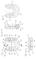
- a holder 30 From the front view of a holder 30 according to the invention 1a shows the fork-shaped structure, which comprises two approximately parallel holding arms 34, which in its foot area with a semicircular Cross yoke 42 connected to one another and formed in one piece are.
- the holding arms 34 are mirror-symmetrical to one another trained and only include a space on the side, in which a free side, insertion opening 32nd called, a cutting tooth in the direction of arrow B inserted is.
- the Holding arms 34 On their mutually facing plant sides 36, the Holding arms 34 a bar 40 with a rectangular cross section, which is arranged approximately in the middle on the plant side 36 and extends over the two holding arms 34 and the transverse yoke 42. In the bar 40 are approximately in the middle of the Semi-circular recesses 38 are introduced, which for the partial inclusion of a fastening pin serve.
- the strip 40 points to form a rectangular guide in the Cross-section an approximately rectangular or square Cross section on. This is in particular from FIG. 1b, which a cross-sectional view according to section A-A and 1d, which is a cross-sectional view according to section B-B.
- Figure 1a shows the side of the bracket 30, which for attachment provided on a base body of an earth drilling device is.
- the outside of the holder 30 has a sloping underside 43, to which in protected Arrangement of a weld seam can be provided can.
- At the free ends of the holding arms 34 there is also one Chamfer 48 provided, which in any case for the simplified Attaching the bracket to a base body of the earth-working machine serves.
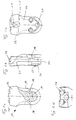
- FIG. 2a An underside of a facing the earth-working machine Cutting tooth 10 according to the invention is shown in FIG. 2a.
- the approximately cuboid cutting tooth 10 has a cutting head 12 and an approximately tongue-shaped Tooth shaft 14 on.
- FIG. 12 As from the side view according to Figure 2b and the top view 2d can be clearly seen from FIG Cutting head 12 a receiving device for pin-shaped Cutting devices 26 are provided.
- FIG. 3a shows the inner broad side of the cutting tooth arrangement according to the invention 1, which in operation is the base body of the earth-working machine is facing.
- the toothed shaft is in the assembled, inserted position 14 of the cutting tooth 10 only laterally from the holding arms 34 of the holding device 30 comprises.
- the Broad sides of the cutting tooth 10 are thus exposed, whereby however, one side through the base body of the not shown Soil cultivation equipment is covered.
- Inserting the cutting tooth 10 in the insertion direction P in the Bracket 30 is not fixed in position by means of illustrated fastening pins 5.
- the fastening pins 5 are inserted into passages 3, which through the recesses 18 on the cutting tooth 10 and the semicircular Recesses 38 in the edge region of the contact sides 36 of the holding arms 34 are formed.
Landscapes
- Engineering & Computer Science (AREA)
- Life Sciences & Earth Sciences (AREA)
- Geology (AREA)
- Mining & Mineral Resources (AREA)
- Mechanical Engineering (AREA)
- Physics & Mathematics (AREA)
- Environmental & Geological Engineering (AREA)
- Fluid Mechanics (AREA)
- General Life Sciences & Earth Sciences (AREA)
- Geochemistry & Mineralogy (AREA)
- Component Parts Of Construction Machinery (AREA)
- Polishing Bodies And Polishing Tools (AREA)
- Shearing Machines (AREA)
- Mechanical Treatment Of Semiconductor (AREA)
- Shovels (AREA)
- Control And Other Processes For Unpacking Of Materials (AREA)
- Non-Silver Salt Photosensitive Materials And Non-Silver Salt Photography (AREA)
- Magnetic Heads (AREA)
- Load-Engaging Elements For Cranes (AREA)
- Forklifts And Lifting Vehicles (AREA)
Priority Applications (1)
| Application Number | Priority Date | Filing Date | Title |
|---|---|---|---|
| DE50101470.5T DE50101470C5 (de) | 2001-01-12 | 2001-11-23 | Schneidezahnanordnung |
Applications Claiming Priority (2)
| Application Number | Priority Date | Filing Date | Title |
|---|---|---|---|
| DE20100550U DE20100550U1 (de) | 2001-01-12 | 2001-01-12 | Schneidzahnanordnung |
| DE20100550U | 2001-01-12 |
Publications (3)
| Publication Number | Publication Date |
|---|---|
| EP1223302A2 true EP1223302A2 (fr) | 2002-07-17 |
| EP1223302A3 EP1223302A3 (fr) | 2003-03-19 |
| EP1223302B1 EP1223302B1 (fr) | 2004-02-11 |
Family
ID=7951529
Family Applications (1)
| Application Number | Title | Priority Date | Filing Date |
|---|---|---|---|
| EP01127951A Expired - Lifetime EP1223302B1 (fr) | 2001-01-12 | 2001-11-23 | Ensemble de dent de coupe |
Country Status (7)
| Country | Link |
|---|---|
| EP (1) | EP1223302B1 (fr) |
| AT (1) | ATE259465T1 (fr) |
| DE (2) | DE20100550U1 (fr) |
| DK (1) | DK1223302T3 (fr) |
| ES (1) | ES2215839T3 (fr) |
| HK (1) | HK1046162B (fr) |
| PT (1) | PT1223302E (fr) |
Cited By (3)
| Publication number | Priority date | Publication date | Assignee | Title |
|---|---|---|---|---|
| EP2545757A1 (fr) | 2011-07-12 | 2013-01-16 | Betek GmbH & Co. KG | Power harrow tines |
| AT16203U1 (de) * | 2017-11-14 | 2019-03-15 | Dr Holger Selg | In die untere Stirnfläche einer hohlzylindrischen Wandung eines Erdbohrers einzubringende Halter-Vorrichtung |
| DE102017126726A1 (de) * | 2017-11-14 | 2019-05-16 | Holger Selg | Halter-Vorrichtung und Stollenkörper eines Erdbohrers |
Families Citing this family (2)
| Publication number | Priority date | Publication date | Assignee | Title |
|---|---|---|---|---|
| DE102024111644A1 (de) * | 2024-04-25 | 2025-10-30 | Bauer Maschinen Gmbh | Abtragszahn und verfahren zum abtragen von boden |
| DE102024111645A1 (de) * | 2024-04-25 | 2025-10-30 | Bauer Maschinen Gmbh | Element zum einsatz bei der bodenbearbeitung und verfahren zum bearbeiten von boden |
Citations (1)
| Publication number | Priority date | Publication date | Assignee | Title |
|---|---|---|---|---|
| DE4002907A1 (de) | 1990-02-01 | 1991-08-08 | Leffer Stahl & App | Schneidkrone fuer bohrrohre mit einfach auswechselbaren zaehnen |
Family Cites Families (1)
| Publication number | Priority date | Publication date | Assignee | Title |
|---|---|---|---|---|
| US3079710A (en) * | 1961-06-22 | 1963-03-05 | Esco Corp | Ground-working tooth and method |
-
2001
- 2001-01-12 DE DE20100550U patent/DE20100550U1/de not_active Expired - Lifetime
- 2001-11-23 ES ES01127951T patent/ES2215839T3/es not_active Expired - Lifetime
- 2001-11-23 PT PT01127951T patent/PT1223302E/pt unknown
- 2001-11-23 AT AT01127951T patent/ATE259465T1/de active
- 2001-11-23 DE DE50101470.5T patent/DE50101470C5/de not_active Expired - Lifetime
- 2001-11-23 DK DK01127951T patent/DK1223302T3/da active
- 2001-11-23 EP EP01127951A patent/EP1223302B1/fr not_active Expired - Lifetime
-
2002
- 2002-10-28 HK HK02107783.4A patent/HK1046162B/zh not_active IP Right Cessation
Patent Citations (1)
| Publication number | Priority date | Publication date | Assignee | Title |
|---|---|---|---|---|
| DE4002907A1 (de) | 1990-02-01 | 1991-08-08 | Leffer Stahl & App | Schneidkrone fuer bohrrohre mit einfach auswechselbaren zaehnen |
Cited By (4)
| Publication number | Priority date | Publication date | Assignee | Title |
|---|---|---|---|---|
| EP2545757A1 (fr) | 2011-07-12 | 2013-01-16 | Betek GmbH & Co. KG | Power harrow tines |
| AT16203U1 (de) * | 2017-11-14 | 2019-03-15 | Dr Holger Selg | In die untere Stirnfläche einer hohlzylindrischen Wandung eines Erdbohrers einzubringende Halter-Vorrichtung |
| DE102017126726A1 (de) * | 2017-11-14 | 2019-05-16 | Holger Selg | Halter-Vorrichtung und Stollenkörper eines Erdbohrers |
| DE102017126726B4 (de) | 2017-11-14 | 2020-01-09 | Holger Selg | Halter-Vorrichtung und Stollenkörper eines Erdbohrers |
Also Published As
| Publication number | Publication date |
|---|---|
| HK1046162B (zh) | 2004-09-10 |
| DE50101470C5 (de) | 2017-11-16 |
| EP1223302A3 (fr) | 2003-03-19 |
| DE20100550U1 (de) | 2001-04-19 |
| HK1046162A1 (en) | 2002-12-27 |
| ES2215839T3 (es) | 2004-10-16 |
| DE50101470D1 (de) | 2004-03-18 |
| DK1223302T3 (da) | 2004-06-14 |
| ATE259465T1 (de) | 2004-02-15 |
| EP1223302B1 (fr) | 2004-02-11 |
| PT1223302E (pt) | 2004-06-30 |
Similar Documents
| Publication | Publication Date | Title |
|---|---|---|
| EP0656989B1 (fr) | Element tranchant pour une haveuse | |
| DE3436309A1 (de) | Riegelelement fuer ein verschleissteilsystem | |
| DE3513670C2 (de) | Anordnung zur Befestigung von hülsenförmigen Zähnen | |
| DE3046922C2 (de) | Druckluft-Handbohrmaschine | |
| DE3004568A1 (de) | Schneidwerkzeug mit einem auswechselbaren hartmetall-schneideinsatz | |
| EP1223302B1 (fr) | Ensemble de dent de coupe | |
| WO2014026815A1 (fr) | Outil pour le travail des champs | |
| DE10205644B4 (de) | Bohrwerkzeug | |
| DE102012103440B4 (de) | Kufensegment für einen Kantenschutz einer Straßenfräsmaschine und Kantenschutz für eine Straßenfräsmaschine | |
| DE20300239U1 (de) | Kratzer für Kettenkratzförderer | |
| DE3502250C2 (fr) | ||
| EP2394790B1 (fr) | Mors de rechange pour un étau | |
| DE3425012A1 (de) | Werkzeughaltevorrichtung zur montage von schneidspitzen | |
| DE3531781C1 (en) | Holder for a plough cutter for coal-winning machines | |
| DE833117C (de) | Kreissaegeblatt mit auswechselbaren Zaehnen | |
| DE1484710B1 (de) | Baggerzahn | |
| DE102017126726B4 (de) | Halter-Vorrichtung und Stollenkörper eines Erdbohrers | |
| DE1484710C (de) | Baggerzahn | |
| DE2930766A1 (de) | Halterung fuer baggerzaehne an schaufeln, eimern, kuebeln o.dgl. | |
| DE8328156U1 (de) | Bohrwerkzeug zum bohren von tiefen bohrungen in gestein | |
| DE3021733A1 (de) | Rotary-kegelrollenmeissel | |
| DE19802225A1 (de) | Meißelanordnung für Gewinnungshobel, insbesondere Kohlenhobel | |
| DE1755028C (de) | Verbindergleiskette, insbesondere für Panzerkampfwagen | |
| DE3526994C1 (de) | Vorrichtung zur Aufnahme eines Meißels für Schräm- und Bohrmaschinen und dgl., insbesondere für Vortriebs- und Gewinnungsmaschinen | |
| DE563379C (de) | Erweiterungsstossbohrer mit einem Widerlagerstueck |
Legal Events
| Date | Code | Title | Description |
|---|---|---|---|
| PUAI | Public reference made under article 153(3) epc to a published international application that has entered the european phase |
Free format text: ORIGINAL CODE: 0009012 |
|
| AK | Designated contracting states |
Kind code of ref document: A2 Designated state(s): AT BE CH CY DE DK ES FI FR GB GR IE IT LI LU MC NL PT SE TR |
|
| AX | Request for extension of the european patent |
Free format text: AL;LT;LV;MK;RO;SI |
|
| PUAL | Search report despatched |
Free format text: ORIGINAL CODE: 0009013 |
|
| AK | Designated contracting states |
Kind code of ref document: A3 Designated state(s): AT BE CH CY DE DK ES FI FR GB GR IE IT LI LU MC NL PT SE TR Designated state(s): AT BE CH CY DE DK ES FI FR GB GR IE IT LI LU MC NL PT SE TR |
|
| AX | Request for extension of the european patent |
Extension state: AL LT LV MK RO SI |
|
| RIC1 | Information provided on ipc code assigned before grant |
Ipc: 7E 21B 10/62 A Ipc: 7E 02F 9/28 B |
|
| 17P | Request for examination filed |
Effective date: 20030211 |
|
| GRAH | Despatch of communication of intention to grant a patent |
Free format text: ORIGINAL CODE: EPIDOS IGRA |
|
| GRAS | Grant fee paid |
Free format text: ORIGINAL CODE: EPIDOSNIGR3 |
|
| AKX | Designation fees paid |
Designated state(s): AT BE CH CY DE DK ES FI FR GB GR IE IT LI LU MC NL PT SE TR |
|
| GRAA | (expected) grant |
Free format text: ORIGINAL CODE: 0009210 |
|
| AK | Designated contracting states |
Kind code of ref document: B1 Designated state(s): AT BE CH CY DE DK ES FI FR GB GR IE IT LI LU MC NL PT SE TR |
|
| PG25 | Lapsed in a contracting state [announced via postgrant information from national office to epo] |
Ref country code: TR Free format text: LAPSE BECAUSE OF FAILURE TO SUBMIT A TRANSLATION OF THE DESCRIPTION OR TO PAY THE FEE WITHIN THE PRESCRIBED TIME-LIMIT Effective date: 20040211 Ref country code: CY Free format text: LAPSE BECAUSE OF FAILURE TO SUBMIT A TRANSLATION OF THE DESCRIPTION OR TO PAY THE FEE WITHIN THE PRESCRIBED TIME-LIMIT Effective date: 20040211 |
|
| REG | Reference to a national code |
Ref country code: GB Ref legal event code: FG4D Free format text: NOT ENGLISH |
|
| REG | Reference to a national code |
Ref country code: CH Ref legal event code: EP |
|
| REG | Reference to a national code |
Ref country code: IE Ref legal event code: FG4D Free format text: GERMAN |
|
| REF | Corresponds to: |
Ref document number: 50101470 Country of ref document: DE Date of ref document: 20040318 Kind code of ref document: P |
|
| REG | Reference to a national code |
Ref country code: CH Ref legal event code: NV Representative=s name: SCHMAUDER & PARTNER AG PATENTANWALTSBUERO |
|
| GBT | Gb: translation of ep patent filed (gb section 77(6)(a)/1977) | ||
| REG | Reference to a national code |
Ref country code: GR Ref legal event code: EP Ref document number: 20040401159 Country of ref document: GR |
|
| REG | Reference to a national code |
Ref country code: DK Ref legal event code: T3 |
|
| REG | Reference to a national code |
Ref country code: PT Ref legal event code: SC4A Free format text: AVAILABILITY OF NATIONAL TRANSLATION Effective date: 20040505 |
|
| REG | Reference to a national code |
Ref country code: HK Ref legal event code: GR Ref document number: 1046162 Country of ref document: HK |
|
| REG | Reference to a national code |
Ref country code: ES Ref legal event code: FG2A Ref document number: 2215839 Country of ref document: ES Kind code of ref document: T3 |
|
| ET | Fr: translation filed | ||
| PG25 | Lapsed in a contracting state [announced via postgrant information from national office to epo] |
Ref country code: LU Free format text: LAPSE BECAUSE OF NON-PAYMENT OF DUE FEES Effective date: 20041123 |
|
| PG25 | Lapsed in a contracting state [announced via postgrant information from national office to epo] |
Ref country code: MC Free format text: LAPSE BECAUSE OF NON-PAYMENT OF DUE FEES Effective date: 20041130 |
|
| PLBE | No opposition filed within time limit |
Free format text: ORIGINAL CODE: 0009261 |
|
| STAA | Information on the status of an ep patent application or granted ep patent |
Free format text: STATUS: NO OPPOSITION FILED WITHIN TIME LIMIT |
|
| 26N | No opposition filed |
Effective date: 20041112 |
|
| REG | Reference to a national code |
Ref country code: CH Ref legal event code: PCAR Free format text: SCHMAUDER & PARTNER AG PATENT- UND MARKENANWAELTE VSP;ZWAENGIWEG 7;8038 ZUERICH (CH) |
|
| PGFP | Annual fee paid to national office [announced via postgrant information from national office to epo] |
Ref country code: GR Payment date: 20101101 Year of fee payment: 10 |
|
| PGFP | Annual fee paid to national office [announced via postgrant information from national office to epo] |
Ref country code: DK Payment date: 20111110 Year of fee payment: 11 |
|
| REG | Reference to a national code |
Ref country code: CH Ref legal event code: PFA Owner name: BAUER MASCHINEN GMBH Free format text: BAUER MASCHINEN GMBH#WITTELSBACHERSTRASSE 5#86529 SCHROBENHAUSEN (DE) -TRANSFER TO- BAUER MASCHINEN GMBH#BAUER-STRASSE 1#86529 SCHROBENHAUSEN (DE) |
|
| PGFP | Annual fee paid to national office [announced via postgrant information from national office to epo] |
Ref country code: BE Payment date: 20111205 Year of fee payment: 11 |
|
| PGFP | Annual fee paid to national office [announced via postgrant information from national office to epo] |
Ref country code: IE Payment date: 20121109 Year of fee payment: 12 Ref country code: FI Payment date: 20121119 Year of fee payment: 12 |
|
| PGFP | Annual fee paid to national office [announced via postgrant information from national office to epo] |
Ref country code: PT Payment date: 20120523 Year of fee payment: 12 |
|
| REG | Reference to a national code |
Ref country code: DE Ref legal event code: R008 Ref document number: 50101470 Country of ref document: DE |
|
| BERE | Be: lapsed |
Owner name: *BAUER MASCHINEN G.M.B.H. Effective date: 20121130 |
|
| REG | Reference to a national code |
Ref country code: DE Ref legal event code: R039 Ref document number: 50101470 Country of ref document: DE Effective date: 20130402 |
|
| REG | Reference to a national code |
Ref country code: DK Ref legal event code: EBP |
|
| PG25 | Lapsed in a contracting state [announced via postgrant information from national office to epo] |
Ref country code: GR Free format text: LAPSE BECAUSE OF NON-PAYMENT OF DUE FEES Effective date: 20130604 Ref country code: BE Free format text: LAPSE BECAUSE OF NON-PAYMENT OF DUE FEES Effective date: 20121130 |
|
| REG | Reference to a national code |
Ref country code: GR Ref legal event code: ML Ref document number: 20040401159 Country of ref document: GR Effective date: 20130604 |
|
| PG25 | Lapsed in a contracting state [announced via postgrant information from national office to epo] |
Ref country code: DK Free format text: LAPSE BECAUSE OF NON-PAYMENT OF DUE FEES Effective date: 20121130 |
|
| REG | Reference to a national code |
Ref country code: PT Ref legal event code: MM4A Free format text: LAPSE DUE TO NON-PAYMENT OF FEES Effective date: 20140523 |
|
| REG | Reference to a national code |
Ref country code: IE Ref legal event code: MM4A |
|
| PG25 | Lapsed in a contracting state [announced via postgrant information from national office to epo] |
Ref country code: PT Free format text: LAPSE BECAUSE OF NON-PAYMENT OF DUE FEES Effective date: 20140523 Ref country code: FI Free format text: LAPSE BECAUSE OF NON-PAYMENT OF DUE FEES Effective date: 20131123 |
|
| PG25 | Lapsed in a contracting state [announced via postgrant information from national office to epo] |
Ref country code: IE Free format text: LAPSE BECAUSE OF NON-PAYMENT OF DUE FEES Effective date: 20131123 |
|
| PGFP | Annual fee paid to national office [announced via postgrant information from national office to epo] |
Ref country code: SE Payment date: 20141124 Year of fee payment: 14 |
|
| PGFP | Annual fee paid to national office [announced via postgrant information from national office to epo] |
Ref country code: NL Payment date: 20141126 Year of fee payment: 14 |
|
| REG | Reference to a national code |
Ref country code: FR Ref legal event code: PLFP Year of fee payment: 15 |
|
| REG | Reference to a national code |
Ref country code: NL Ref legal event code: MM Effective date: 20151201 |
|
| PG25 | Lapsed in a contracting state [announced via postgrant information from national office to epo] |
Ref country code: SE Free format text: LAPSE BECAUSE OF NON-PAYMENT OF DUE FEES Effective date: 20151124 |
|
| PG25 | Lapsed in a contracting state [announced via postgrant information from national office to epo] |
Ref country code: NL Free format text: LAPSE BECAUSE OF NON-PAYMENT OF DUE FEES Effective date: 20151201 |
|
| REG | Reference to a national code |
Ref country code: FR Ref legal event code: PLFP Year of fee payment: 16 |
|
| PGFP | Annual fee paid to national office [announced via postgrant information from national office to epo] |
Ref country code: ES Payment date: 20161124 Year of fee payment: 16 |
|
| REG | Reference to a national code |
Ref country code: DE Ref legal event code: R043 Ref document number: 50101470 Country of ref document: DE |
|
| REG | Reference to a national code |
Ref country code: DE Ref legal event code: R206 Ref document number: 50101470 Country of ref document: DE |
|
| REG | Reference to a national code |
Ref country code: FR Ref legal event code: PLFP Year of fee payment: 17 |
|
| PG25 | Lapsed in a contracting state [announced via postgrant information from national office to epo] |
Ref country code: ES Free format text: LAPSE BECAUSE OF NON-PAYMENT OF DUE FEES Effective date: 20171124 |
|
| REG | Reference to a national code |
Ref country code: DE Ref legal event code: R082 Ref document number: 50101470 Country of ref document: DE Representative=s name: WUNDERLICH & HEIM PATENTANWAELTE PARTNERSCHAFT, DE |
|
| PGFP | Annual fee paid to national office [announced via postgrant information from national office to epo] |
Ref country code: DE Payment date: 20201124 Year of fee payment: 20 Ref country code: AT Payment date: 20201117 Year of fee payment: 20 Ref country code: CH Payment date: 20201124 Year of fee payment: 20 Ref country code: FR Payment date: 20201119 Year of fee payment: 20 Ref country code: GB Payment date: 20201123 Year of fee payment: 20 Ref country code: IT Payment date: 20201130 Year of fee payment: 20 |
|
| REG | Reference to a national code |
Ref country code: DE Ref legal event code: R071 Ref document number: 50101470 Country of ref document: DE |
|
| REG | Reference to a national code |
Ref country code: GB Ref legal event code: PE20 Expiry date: 20211122 |
|
| REG | Reference to a national code |
Ref country code: AT Ref legal event code: MK07 Ref document number: 259465 Country of ref document: AT Kind code of ref document: T Effective date: 20211123 |
|
| PG25 | Lapsed in a contracting state [announced via postgrant information from national office to epo] |
Ref country code: GB Free format text: LAPSE BECAUSE OF EXPIRATION OF PROTECTION Effective date: 20211122 |
|
| P01 | Opt-out of the competence of the unified patent court (upc) registered |
Effective date: 20240516 |