EP1223308A2 - Refroidissement d'une composante d'une turbomachine - Google Patents
Refroidissement d'une composante d'une turbomachine Download PDFInfo
- Publication number
- EP1223308A2 EP1223308A2 EP01129169A EP01129169A EP1223308A2 EP 1223308 A2 EP1223308 A2 EP 1223308A2 EP 01129169 A EP01129169 A EP 01129169A EP 01129169 A EP01129169 A EP 01129169A EP 1223308 A2 EP1223308 A2 EP 1223308A2
- Authority
- EP
- European Patent Office
- Prior art keywords
- channel
- flow
- cooling
- deflection
- section
- Prior art date
- Legal status (The legal status is an assumption and is not a legal conclusion. Google has not performed a legal analysis and makes no representation as to the accuracy of the status listed.)
- Granted
Links
Images


Classifications
-
- F—MECHANICAL ENGINEERING; LIGHTING; HEATING; WEAPONS; BLASTING
- F01—MACHINES OR ENGINES IN GENERAL; ENGINE PLANTS IN GENERAL; STEAM ENGINES
- F01D—NON-POSITIVE DISPLACEMENT MACHINES OR ENGINES, e.g. STEAM TURBINES
- F01D25/00—Component parts, details, or accessories, not provided for in, or of interest apart from, other groups
- F01D25/08—Cooling; Heating; Heat-insulation
- F01D25/12—Cooling
-
- F—MECHANICAL ENGINEERING; LIGHTING; HEATING; WEAPONS; BLASTING
- F01—MACHINES OR ENGINES IN GENERAL; ENGINE PLANTS IN GENERAL; STEAM ENGINES
- F01D—NON-POSITIVE DISPLACEMENT MACHINES OR ENGINES, e.g. STEAM TURBINES
- F01D5/00—Blades; Blade-carrying members; Heating, heat-insulating, cooling or antivibration means on the blades or the members
- F01D5/12—Blades
- F01D5/14—Form or construction
- F01D5/18—Hollow blades, i.e. blades with cooling or heating channels or cavities; Heating, heat-insulating or cooling means on blades
- F01D5/187—Convection cooling
Definitions
- the present invention relates to a component a turbomachine, in particular a turbine blade, which can be flowed through by a cooling medium Cooling channel with at least one through the wall of the cooling channel formed deflection through which the flow of the cooling medium from a first Canal section into a downstream second Channel section is deflected, being in the area of Deflecting at least one flow guiding element in the Cooling channel is arranged through which the cooling channel in the diversion into an inner and an outer Flow channel is divided.
- a separate cooling duct 2a is additionally provided, via which part of the cooling air is guided to the front and tip of the blade in order to exit there via corresponding openings 4.
- the flow pattern of the cooling air within the airfoil is indicated by the arrows.
- 180 ° deflections 5 are required in the vicinity of the blade tip or the blade root, which connect the different sections of the cooling air duct 2 to one another.
- complicated flow patterns with dead water areas develop, which lead to large pressure losses over the length of the cooling air duct 2 and thus require an increased pumping capacity for the transport of the cooling air.
- the task is performed using the component Claim 1 solved.
- Advantageous configurations the component are the subject of the subclaims.
- the proposed solution is therefore a Reduction of pressure losses in the redirection simultaneous homogenization of the heat transfer between the cooling medium and the wall material of the Component reached.
- the present design is regardless of the further configuration of the Component, in particular regardless of the rib configuration in the first and second channel section, in Hereinafter also referred to as the inlet and outlet duct, as well as possible curves on the outer Edge areas of the deflection. Such details, that with a variety of gas turbine blades occur do not affect the beneficial Effect of the present invention.
- the drilling leads to the dissolution of the dead water areas and thus contributes to a homogenization of the heat transfer. Furthermore, these bores can bring about the desired side effect that dust particles in the cooling medium are blown out through the bores. To reinforce this side effect, the longitudinal axes of the bores are aligned approximately in the direction of the local streamlines of the flow of the cooling medium in the cooling channel. Due to the low adjacent flow velocity, the additional bores only make a small contribution to the global pressure loss via the cooling channel, which, due to the advantageous effect mentioned above, is hardly noticeable to minimize the pressure loss.
- the thickness of the partition wall increases in the region of the deflection, in order to reduce the corresponding constriction within the region due to this increase in thickness inner flow channel.
- the shape of the contour of this partition wall, which separates the outlet duct from the inlet duct, can be different in order to bring about the effect mentioned.
- the flow guide element is preferably such trained and arranged within the deflection, that about 25 to 45% of the mass flow from the Inlet channel into the flow entering the deflection the area within the flow guide element, i.e. into the inner flow channel, enters and the rest outside the baffle, i.e. in the outer flow channel, flows.
- the mass flow ratio corresponds to that Entry cross-sectional area ratio of the outer and inner flow channel.
- the area ratio on The outlet duct should be roughly the same as the inlet duct correspond, i.e. it shouldn't be more than 20% deviate from this ratio.
- the round baffle vary in thickness, or even again with Guide devices should be provided.
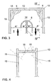
- FIG. 3 shows a schematic representation Embodiment for the design of the cooling channel deflection 5 the component of a turbomachine according to the present invention.
- the flow direction of the cooling medium is in turn through in this figure thick arrows indicated.
- the cooling medium overflows a first channel section 9 in the deflection 5 and thence to a second canal section 10.
- the two Channel sections 9 and 10 are used in this example separated from each other by a partition 11, the Is part of the cooling channel wall 12.
- Such one Cooling channel can be in a usual gas turbine blade, as shown for example in FIG. 1, be arranged.
- the deflection baffle is designed such that approximately 25 to 45% of the mass flow of the flow entering the deflection 5 from the inlet duct 9 flows into the area of the inner flow channel 13 and the rest flows into the area of the outer flow channel 14.
- the mass flow ratio corresponds to the inlet area ratio A '/ B'.
- the area ratio at the outlet duct A "/ B" in this example corresponds to the area ratio at the inlet duct and should not deviate more than ⁇ 20% from A '/ B'.
- the holes 15 depending on location with its axis of drilling approximately in Direction of the streamlines of the flow of the cooling medium aligned so that - as an additional side effect - the discharge of small particles or dust in the Cooling air can take place via the bores 15.
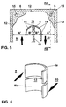
- FIG. 5 shows another preferred Embodiment of the invention shown in Figure 3.
- the flow guide element 8 has a number of bores 16, which contribute to dust and Dirt accumulation in the outer 14 or inner 13 Avoid flow channel.
- Figure 6 shows another Possibility to achieve this effect.
- the Flow guide element is in several sub-elements, 8a and 8b, divided between which a gap is trained, which has the same effect as the bores 16 in FIG. 5.
Landscapes
- Engineering & Computer Science (AREA)
- Mechanical Engineering (AREA)
- General Engineering & Computer Science (AREA)
- Turbine Rotor Nozzle Sealing (AREA)
Applications Claiming Priority (4)
| Application Number | Priority Date | Filing Date | Title |
|---|---|---|---|
| DE10062906 | 2000-12-16 | ||
| DE10062906 | 2000-12-16 | ||
| DE10126215 | 2001-05-30 | ||
| DE10126215 | 2001-05-30 |
Publications (3)
| Publication Number | Publication Date |
|---|---|
| EP1223308A2 true EP1223308A2 (fr) | 2002-07-17 |
| EP1223308A3 EP1223308A3 (fr) | 2004-01-02 |
| EP1223308B1 EP1223308B1 (fr) | 2007-01-24 |
Family
ID=26007995
Family Applications (1)
| Application Number | Title | Priority Date | Filing Date |
|---|---|---|---|
| EP01129169A Expired - Lifetime EP1223308B1 (fr) | 2000-12-16 | 2001-12-08 | Composante d'une turbomachine |
Country Status (3)
| Country | Link |
|---|---|
| US (1) | US6595750B2 (fr) |
| EP (1) | EP1223308B1 (fr) |
| DE (1) | DE50111949D1 (fr) |
Cited By (6)
| Publication number | Priority date | Publication date | Assignee | Title |
|---|---|---|---|---|
| EP1456505A1 (fr) * | 2001-12-10 | 2004-09-15 | ALSTOM Technology Ltd | Piece a sollicitation thermique |
| EP1607576A2 (fr) | 2004-06-14 | 2005-12-21 | United Technologies Corporation | Passage coudé de refroidissement d'aile et méthode de fabrication |
| WO2007050205A3 (fr) * | 2005-09-19 | 2007-09-20 | United Technologies Corp | Echangeur thermique compact |
| WO2009118245A1 (fr) * | 2008-03-28 | 2009-10-01 | Alstom Technology Ltd | Aube directrice pour turbine à gaz et turbine à gaz dotée d'une aube directrice de ce type |
| US8985940B2 (en) | 2012-03-30 | 2015-03-24 | Solar Turbines Incorporated | Turbine cooling apparatus |
| WO2016148690A1 (fr) * | 2015-03-17 | 2016-09-22 | Siemens Energy, Inc. | Aube de turbine avec structure de guidage tournante à écoulement sans contrainte |
Families Citing this family (39)
| Publication number | Priority date | Publication date | Assignee | Title |
|---|---|---|---|---|
| US6939102B2 (en) * | 2003-09-25 | 2005-09-06 | Siemens Westinghouse Power Corporation | Flow guide component with enhanced cooling |
| US7377747B2 (en) * | 2005-06-06 | 2008-05-27 | General Electric Company | Turbine airfoil with integrated impingement and serpentine cooling circuit |
| US7445432B2 (en) * | 2006-03-28 | 2008-11-04 | United Technologies Corporation | Enhanced serpentine cooling with U-shaped divider rib |
| TWI448285B (zh) * | 2006-07-13 | 2014-08-11 | Los Angeles Biomed Res Inst | 用以治療白黴菌症(mucormycosis)及其他真菌類疾病之組合物及方法 |
| US7625178B2 (en) * | 2006-08-30 | 2009-12-01 | Honeywell International Inc. | High effectiveness cooled turbine blade |
| US7967563B1 (en) * | 2007-11-19 | 2011-06-28 | Florida Turbine Technologies, Inc. | Turbine blade with tip section cooling channel |
| JP2012520878A (ja) * | 2009-03-19 | 2012-09-10 | ロサンゼルス ビオメドイカル リサーチ インストイトウテ アト ハルボル‐ユーシーエルエー メドイカル センテル | ムコール菌症、及びその他の真菌疾患の治療のためのワクチン組成物、及び方法 |
| US8562286B2 (en) * | 2010-04-06 | 2013-10-22 | United Technologies Corporation | Dead ended bulbed rib geometry for a gas turbine engine |
| GB201102719D0 (en) * | 2011-02-17 | 2011-03-30 | Rolls Royce Plc | Cooled component for the turbine of a gas turbine engine |
| US20120315139A1 (en) * | 2011-06-10 | 2012-12-13 | General Electric Company | Cooling flow control members for turbomachine buckets and method |
| US8807945B2 (en) | 2011-06-22 | 2014-08-19 | United Technologies Corporation | Cooling system for turbine airfoil including ice-cream-cone-shaped pedestals |
| US9228439B2 (en) * | 2012-09-28 | 2016-01-05 | Solar Turbines Incorporated | Cooled turbine blade with leading edge flow redirection and diffusion |
| US20140093388A1 (en) * | 2012-09-28 | 2014-04-03 | Solar Turbines Incorporated | Cooled turbine blade with leading edge flow deflection and division |
| US9638041B2 (en) | 2013-10-23 | 2017-05-02 | General Electric Company | Turbine bucket having non-axisymmetric base contour |
| US9670784B2 (en) | 2013-10-23 | 2017-06-06 | General Electric Company | Turbine bucket base having serpentine cooling passage with leading edge cooling |
| US9528379B2 (en) | 2013-10-23 | 2016-12-27 | General Electric Company | Turbine bucket having serpentine core |
| US9797258B2 (en) * | 2013-10-23 | 2017-10-24 | General Electric Company | Turbine bucket including cooling passage with turn |
| US9551226B2 (en) | 2013-10-23 | 2017-01-24 | General Electric Company | Turbine bucket with endwall contour and airfoil profile |
| EP3277931B1 (fr) | 2015-04-03 | 2020-08-19 | Siemens Aktiengesellschaft | Bord de fuite de pale de turbine à canal d'armature à faible écoulement |
| WO2016163980A1 (fr) * | 2015-04-06 | 2016-10-13 | Siemens Energy, Inc. | Aube de turbine avec système de refroidissement à canal en serpentin avec diviseur de flux amélioré |
| US10107108B2 (en) | 2015-04-29 | 2018-10-23 | General Electric Company | Rotor blade having a flared tip |
| DE102015112643A1 (de) * | 2015-07-31 | 2017-02-02 | Wobben Properties Gmbh | Windenergieanlagen-Rotorblatt |
| US10119406B2 (en) * | 2016-05-12 | 2018-11-06 | General Electric Company | Blade with stress-reducing bulbous projection at turn opening of coolant passages |
| WO2018143997A1 (fr) * | 2017-02-03 | 2018-08-09 | Siemens Aktiengesellschaft | Pale de turbine |
| JP6928170B2 (ja) * | 2017-08-24 | 2021-09-01 | シーメンス アクティエンゲゼルシャフト | タービンロータ翼形、および動翼内の空洞における圧力損失を低減するための対応方法 |
| US10641106B2 (en) | 2017-11-13 | 2020-05-05 | Honeywell International Inc. | Gas turbine engines with improved airfoil dust removal |
| US10718219B2 (en) * | 2017-12-13 | 2020-07-21 | Solar Turbines Incorporated | Turbine blade cooling system with tip diffuser |
| US10502093B2 (en) * | 2017-12-13 | 2019-12-10 | Pratt & Whitney Canada Corp. | Turbine shroud cooling |
| US10570773B2 (en) * | 2017-12-13 | 2020-02-25 | Pratt & Whitney Canada Corp. | Turbine shroud cooling |
| US10533454B2 (en) | 2017-12-13 | 2020-01-14 | Pratt & Whitney Canada Corp. | Turbine shroud cooling |
| US11274569B2 (en) | 2017-12-13 | 2022-03-15 | Pratt & Whitney Canada Corp. | Turbine shroud cooling |
| US10655476B2 (en) * | 2017-12-14 | 2020-05-19 | Honeywell International Inc. | Gas turbine engines with airfoils having improved dust tolerance |
| DE102019125779B4 (de) * | 2019-09-25 | 2024-03-21 | Man Energy Solutions Se | Schaufel einer Strömungsmaschine |
| US11319839B2 (en) | 2019-12-20 | 2022-05-03 | Raytheon Technologies Corporation | Component having a dirt tolerant passage turn |
| CN111852574A (zh) * | 2020-07-27 | 2020-10-30 | 北京全四维动力科技有限公司 | 涡轮叶片及包括其的燃气轮机 |
| US11365645B2 (en) | 2020-10-07 | 2022-06-21 | Pratt & Whitney Canada Corp. | Turbine shroud cooling |
| KR102668653B1 (ko) | 2021-10-27 | 2024-05-22 | 두산에너빌리티 주식회사 | 터빈용 에어포일, 이를 포함하는 터빈 |
| CN115962015A (zh) * | 2023-01-09 | 2023-04-14 | 中国航发湖南动力机械研究所 | 一种涡轮叶片内腔导流结构 |
| US20260098476A1 (en) * | 2024-10-09 | 2026-04-09 | Solar Turbines Incorporated | Turbine blade with cooling features |
Citations (1)
| Publication number | Priority date | Publication date | Assignee | Title |
|---|---|---|---|---|
| US5073086A (en) | 1990-07-03 | 1991-12-17 | Rolls-Royce Plc | Cooled aerofoil blade |
Family Cites Families (7)
| Publication number | Priority date | Publication date | Assignee | Title |
|---|---|---|---|---|
| US4775296A (en) * | 1981-12-28 | 1988-10-04 | United Technologies Corporation | Coolable airfoil for a rotary machine |
| US4474532A (en) * | 1981-12-28 | 1984-10-02 | United Technologies Corporation | Coolable airfoil for a rotary machine |
| GB2165315B (en) * | 1984-10-04 | 1987-12-31 | Rolls Royce | Improvements in or relating to hollow fluid cooled turbine blades |
| GB9402442D0 (en) | 1994-02-09 | 1994-04-20 | Rolls Royce Plc | Cooling air cooled gas turbine aerofoil |
| JP3137527B2 (ja) | 1994-04-21 | 2001-02-26 | 三菱重工業株式会社 | ガスタービン動翼チップ冷却装置 |
| US5498126A (en) * | 1994-04-28 | 1996-03-12 | United Technologies Corporation | Airfoil with dual source cooling |
| DE19921644B4 (de) * | 1999-05-10 | 2012-01-05 | Alstom | Kühlbare Schaufel für eine Gasturbine |
-
2001
- 2001-12-08 DE DE50111949T patent/DE50111949D1/de not_active Expired - Lifetime
- 2001-12-08 EP EP01129169A patent/EP1223308B1/fr not_active Expired - Lifetime
- 2001-12-13 US US10/013,666 patent/US6595750B2/en not_active Expired - Lifetime
Patent Citations (1)
| Publication number | Priority date | Publication date | Assignee | Title |
|---|---|---|---|---|
| US5073086A (en) | 1990-07-03 | 1991-12-17 | Rolls-Royce Plc | Cooled aerofoil blade |
Cited By (10)
| Publication number | Priority date | Publication date | Assignee | Title |
|---|---|---|---|---|
| EP1456505A1 (fr) * | 2001-12-10 | 2004-09-15 | ALSTOM Technology Ltd | Piece a sollicitation thermique |
| US7137784B2 (en) | 2001-12-10 | 2006-11-21 | Alstom Technology Ltd | Thermally loaded component |
| EP1607576A2 (fr) | 2004-06-14 | 2005-12-21 | United Technologies Corporation | Passage coudé de refroidissement d'aile et méthode de fabrication |
| EP1607576A3 (fr) * | 2004-06-14 | 2009-01-14 | United Technologies Corporation | Passage coudé de refroidissement d'aile et méthode de fabrication |
| WO2007050205A3 (fr) * | 2005-09-19 | 2007-09-20 | United Technologies Corp | Echangeur thermique compact |
| WO2009118245A1 (fr) * | 2008-03-28 | 2009-10-01 | Alstom Technology Ltd | Aube directrice pour turbine à gaz et turbine à gaz dotée d'une aube directrice de ce type |
| US8801366B2 (en) | 2008-03-28 | 2014-08-12 | Alstom Technology Ltd. | Stator blade for a gas turbine and gas turbine having same |
| US8985940B2 (en) | 2012-03-30 | 2015-03-24 | Solar Turbines Incorporated | Turbine cooling apparatus |
| WO2016148690A1 (fr) * | 2015-03-17 | 2016-09-22 | Siemens Energy, Inc. | Aube de turbine avec structure de guidage tournante à écoulement sans contrainte |
| US10196906B2 (en) | 2015-03-17 | 2019-02-05 | Siemens Energy, Inc. | Turbine blade with a non-constraint flow turning guide structure |
Also Published As
| Publication number | Publication date |
|---|---|
| US6595750B2 (en) | 2003-07-22 |
| US20020176776A1 (en) | 2002-11-28 |
| DE50111949D1 (de) | 2007-03-15 |
| EP1223308A3 (fr) | 2004-01-02 |
| EP1223308B1 (fr) | 2007-01-24 |
Similar Documents
| Publication | Publication Date | Title |
|---|---|---|
| EP1223308B1 (fr) | Composante d'une turbomachine | |
| EP1113145B1 (fr) | Aube pour turbine a gaz avec section de mesure sur le bord de fuite | |
| DE10001109B4 (de) | Gekühlte Schaufel für eine Gasturbine | |
| DE69105837T2 (de) | Gekühlte Turbinenschaufel. | |
| EP2087206B1 (fr) | Aube de turbine | |
| EP1266127B1 (fr) | Systeme de refroidissement pour aube de turbine | |
| DE19921644A1 (de) | Kühlbare Schaufel für eine Gasturbine | |
| EP1126136B1 (fr) | Aube de turbine avec carenage d'extremité refroidie | |
| CH697919A2 (de) | Turbinenblatt mit konkavem Kühlkanal und darin angeordneten, entgegengesetzte Drallströme bewirkende Turbulatoren. | |
| EP2304185A1 (fr) | Aube de turbine pour une turbine à gaz et noyau de coulée pour sa fabrication | |
| DE102004054294A1 (de) | Kühlsystem für Plattformkanten von Leitradsegmenten | |
| EP0798448A2 (fr) | Système et dispositif pour réfroidir une paroi chauffée d'un cÔté par un gaz chaud | |
| DE2241194A1 (de) | Stroemungsmaschinenschaufel mit tragfluegelfoermigem querschnittsprofil und mit einer vielzahl von in schaufellaengsrichtung verlaufenden kuehlkanaelen | |
| EP0621920A1 (fr) | Refroidissement de la bande de protection d'une aube de turbine. | |
| EP1004748A2 (fr) | Rotor pour une turbomachine | |
| EP1292760B1 (fr) | Configuration d'une aube de turbine pouvant etre refroidie | |
| EP2087207B1 (fr) | Aube de turbine | |
| DE3534905A1 (de) | Hohle, durch ein stroemungsmittel gekuehlte turbinenschaufel | |
| EP1789653B1 (fr) | Rotor pour un propulseur | |
| EP1288435B1 (fr) | Aube de turbine avec au moins un orifice de refroidissement | |
| DE102004002327A1 (de) | Gekühlte Schaufel für eine Gasturbine | |
| EP1644614B1 (fr) | Aube refroidie pour une turbine a gaz | |
| DE102010044819B4 (de) | Axialturbine und ein Verfahren zum Abführen eines Stroms von einer Axialturbine | |
| DE10236676A1 (de) | Turbinenschaufel für eine Gasturbine mit zumindest einer Kühlungsausnehmung | |
| EP3232001A1 (fr) | Aube rotorique de turbine |
Legal Events
| Date | Code | Title | Description |
|---|---|---|---|
| PUAI | Public reference made under article 153(3) epc to a published international application that has entered the european phase |
Free format text: ORIGINAL CODE: 0009012 |
|
| AK | Designated contracting states |
Kind code of ref document: A2 Designated state(s): AT BE CH CY DE DK ES FI FR GB GR IE IT LI LU MC NL PT SE TR |
|
| AX | Request for extension of the european patent |
Free format text: AL;LT;LV;MK;RO;SI |
|
| PUAL | Search report despatched |
Free format text: ORIGINAL CODE: 0009013 |
|
| AK | Designated contracting states |
Kind code of ref document: A3 Designated state(s): AT BE CH CY DE DK ES FI FR GB GR IE IT LI LU MC NL PT SE TR |
|
| AX | Request for extension of the european patent |
Extension state: AL LT LV MK RO SI |
|
| RAP1 | Party data changed (applicant data changed or rights of an application transferred) |
Owner name: ALSTOM TECHNOLOGY LTD |
|
| 17P | Request for examination filed |
Effective date: 20040527 |
|
| 17Q | First examination report despatched |
Effective date: 20040805 |
|
| AKX | Designation fees paid |
Designated state(s): DE GB |
|
| GRAP | Despatch of communication of intention to grant a patent |
Free format text: ORIGINAL CODE: EPIDOSNIGR1 |
|
| RTI1 | Title (correction) |
Free format text: TURBOMACHINE COMPONENT |
|
| GRAS | Grant fee paid |
Free format text: ORIGINAL CODE: EPIDOSNIGR3 |
|
| GRAA | (expected) grant |
Free format text: ORIGINAL CODE: 0009210 |
|
| AK | Designated contracting states |
Kind code of ref document: B1 Designated state(s): DE GB |
|
| REG | Reference to a national code |
Ref country code: GB Ref legal event code: FG4D Free format text: NOT ENGLISH |
|
| REF | Corresponds to: |
Ref document number: 50111949 Country of ref document: DE Date of ref document: 20070315 Kind code of ref document: P |
|
| GBT | Gb: translation of ep patent filed (gb section 77(6)(a)/1977) |
Effective date: 20070222 |
|
| PLBE | No opposition filed within time limit |
Free format text: ORIGINAL CODE: 0009261 |
|
| STAA | Information on the status of an ep patent application or granted ep patent |
Free format text: STATUS: NO OPPOSITION FILED WITHIN TIME LIMIT |
|
| 26N | No opposition filed |
Effective date: 20071025 |
|
| REG | Reference to a national code |
Ref country code: DE Ref legal event code: R082 Ref document number: 50111949 Country of ref document: DE Representative=s name: ROESLER, UWE, DIPL.-PHYS.UNIV., DE Ref country code: DE Ref legal event code: R081 Ref document number: 50111949 Country of ref document: DE Owner name: GENERAL ELECTRIC TECHNOLOGY GMBH, CH Free format text: FORMER OWNER: ALSTOM TECHNOLOGY LTD., BADEN, CH Ref country code: DE Ref legal event code: R081 Ref document number: 50111949 Country of ref document: DE Owner name: ANSALDO ENERGIA IP UK LIMITED, GB Free format text: FORMER OWNER: ALSTOM TECHNOLOGY LTD., BADEN, CH |
|
| PGFP | Annual fee paid to national office [announced via postgrant information from national office to epo] |
Ref country code: DE Payment date: 20161213 Year of fee payment: 16 Ref country code: GB Payment date: 20161222 Year of fee payment: 16 |
|
| REG | Reference to a national code |
Ref country code: DE Ref legal event code: R082 Ref document number: 50111949 Country of ref document: DE Representative=s name: ROESLER, UWE, DIPL.-PHYS.UNIV., DE Ref country code: DE Ref legal event code: R081 Ref document number: 50111949 Country of ref document: DE Owner name: ANSALDO ENERGIA IP UK LIMITED, GB Free format text: FORMER OWNER: GENERAL ELECTRIC TECHNOLOGY GMBH, BADEN, CH |
|
| REG | Reference to a national code |
Ref country code: GB Ref legal event code: 732E Free format text: REGISTERED BETWEEN 20170824 AND 20170830 |
|
| REG | Reference to a national code |
Ref country code: DE Ref legal event code: R119 Ref document number: 50111949 Country of ref document: DE |
|
| GBPC | Gb: european patent ceased through non-payment of renewal fee |
Effective date: 20171208 |
|
| PG25 | Lapsed in a contracting state [announced via postgrant information from national office to epo] |
Ref country code: DE Free format text: LAPSE BECAUSE OF NON-PAYMENT OF DUE FEES Effective date: 20180703 |
|
| PG25 | Lapsed in a contracting state [announced via postgrant information from national office to epo] |
Ref country code: GB Free format text: LAPSE BECAUSE OF NON-PAYMENT OF DUE FEES Effective date: 20171208 |