EP1223320A2 - Méthode et dispositif de recirculation de gaz d'échappement - Google Patents
Méthode et dispositif de recirculation de gaz d'échappement Download PDFInfo
- Publication number
- EP1223320A2 EP1223320A2 EP01129920A EP01129920A EP1223320A2 EP 1223320 A2 EP1223320 A2 EP 1223320A2 EP 01129920 A EP01129920 A EP 01129920A EP 01129920 A EP01129920 A EP 01129920A EP 1223320 A2 EP1223320 A2 EP 1223320A2
- Authority
- EP
- European Patent Office
- Prior art keywords
- exhaust gas
- gas recirculation
- charging device
- control
- recirculation valve
- Prior art date
- Legal status (The legal status is an assumption and is not a legal conclusion. Google has not performed a legal analysis and makes no representation as to the accuracy of the status listed.)
- Withdrawn
Links
- 238000000034 method Methods 0.000 title claims description 14
- 238000002485 combustion reaction Methods 0.000 claims abstract description 21
- 238000002347 injection Methods 0.000 claims description 9
- 239000007924 injection Substances 0.000 claims description 9
- 239000000446 fuel Substances 0.000 claims description 6
- 230000006866 deterioration Effects 0.000 description 5
- 230000004044 response Effects 0.000 description 3
- 239000000779 smoke Substances 0.000 description 3
- 230000001133 acceleration Effects 0.000 description 2
- 230000006978 adaptation Effects 0.000 description 1
- 230000005540 biological transmission Effects 0.000 description 1
- 230000001276 controlling effect Effects 0.000 description 1
- 239000000498 cooling water Substances 0.000 description 1
- 238000012937 correction Methods 0.000 description 1
- 230000000694 effects Effects 0.000 description 1
- 230000001105 regulatory effect Effects 0.000 description 1
- 230000004043 responsiveness Effects 0.000 description 1
- 238000013519 translation Methods 0.000 description 1
- 230000014616 translation Effects 0.000 description 1
Images
Classifications
-
- F—MECHANICAL ENGINEERING; LIGHTING; HEATING; WEAPONS; BLASTING
- F02—COMBUSTION ENGINES; HOT-GAS OR COMBUSTION-PRODUCT ENGINE PLANTS
- F02D—CONTROLLING COMBUSTION ENGINES
- F02D41/00—Electrical control of supply of combustible mixture or its constituents
- F02D41/0025—Controlling engines characterised by use of non-liquid fuels, pluralities of fuels, or non-fuel substances added to the combustible mixtures
- F02D41/0047—Controlling exhaust gas recirculation [EGR]
- F02D41/005—Controlling exhaust gas recirculation [EGR] according to engine operating conditions
- F02D41/0052—Feedback control of engine parameters, e.g. for control of air/fuel ratio or intake air amount
-
- F—MECHANICAL ENGINEERING; LIGHTING; HEATING; WEAPONS; BLASTING
- F02—COMBUSTION ENGINES; HOT-GAS OR COMBUSTION-PRODUCT ENGINE PLANTS
- F02D—CONTROLLING COMBUSTION ENGINES
- F02D41/00—Electrical control of supply of combustible mixture or its constituents
- F02D41/0002—Controlling intake air
- F02D41/0007—Controlling intake air for control of turbo-charged or super-charged engines
-
- F—MECHANICAL ENGINEERING; LIGHTING; HEATING; WEAPONS; BLASTING
- F02—COMBUSTION ENGINES; HOT-GAS OR COMBUSTION-PRODUCT ENGINE PLANTS
- F02D—CONTROLLING COMBUSTION ENGINES
- F02D41/00—Electrical control of supply of combustible mixture or its constituents
- F02D41/02—Circuit arrangements for generating control signals
- F02D41/14—Introducing closed-loop corrections
- F02D41/1401—Introducing closed-loop corrections characterised by the control or regulation method
-
- F—MECHANICAL ENGINEERING; LIGHTING; HEATING; WEAPONS; BLASTING
- F02—COMBUSTION ENGINES; HOT-GAS OR COMBUSTION-PRODUCT ENGINE PLANTS
- F02D—CONTROLLING COMBUSTION ENGINES
- F02D41/00—Electrical control of supply of combustible mixture or its constituents
- F02D41/02—Circuit arrangements for generating control signals
- F02D41/14—Introducing closed-loop corrections
- F02D41/1401—Introducing closed-loop corrections characterised by the control or regulation method
- F02D2041/1413—Controller structures or design
- F02D2041/1422—Variable gain or coefficients
-
- Y—GENERAL TAGGING OF NEW TECHNOLOGICAL DEVELOPMENTS; GENERAL TAGGING OF CROSS-SECTIONAL TECHNOLOGIES SPANNING OVER SEVERAL SECTIONS OF THE IPC; TECHNICAL SUBJECTS COVERED BY FORMER USPC CROSS-REFERENCE ART COLLECTIONS [XRACs] AND DIGESTS
- Y02—TECHNOLOGIES OR APPLICATIONS FOR MITIGATION OR ADAPTATION AGAINST CLIMATE CHANGE
- Y02T—CLIMATE CHANGE MITIGATION TECHNOLOGIES RELATED TO TRANSPORTATION
- Y02T10/00—Road transport of goods or passengers
- Y02T10/10—Internal combustion engine [ICE] based vehicles
- Y02T10/12—Improving ICE efficiencies
-
- Y—GENERAL TAGGING OF NEW TECHNOLOGICAL DEVELOPMENTS; GENERAL TAGGING OF CROSS-SECTIONAL TECHNOLOGIES SPANNING OVER SEVERAL SECTIONS OF THE IPC; TECHNICAL SUBJECTS COVERED BY FORMER USPC CROSS-REFERENCE ART COLLECTIONS [XRACs] AND DIGESTS
- Y02—TECHNOLOGIES OR APPLICATIONS FOR MITIGATION OR ADAPTATION AGAINST CLIMATE CHANGE
- Y02T—CLIMATE CHANGE MITIGATION TECHNOLOGIES RELATED TO TRANSPORTATION
- Y02T10/00—Road transport of goods or passengers
- Y02T10/10—Internal combustion engine [ICE] based vehicles
- Y02T10/40—Engine management systems
Definitions
- the invention relates to a method for exhaust gas recirculation control in an internal combustion engine with a charging device, exhaust gas recirculation line and exhaust gas recirculation valve where the steps setting the charger and setting the Exhaust gas recirculation valve are provided by means of control signals.
- the invention also relates to a device for carrying out the Method for exhaust gas recirculation control with a control device to control an actuating unit of the charging device and an actuator of the exhaust gas recirculation valve.
- a control device regulates there in a first, low load and / or speed range exhaust gas recirculation and in a second, higher load and / or speed range the boost pressure.
- the control device has a first one Controller with a manipulated variable for changing a variable flow cross-section the turbine of the exhaust gas turbocharger.
- the first, low speed range is about setting this variable flow cross-section with the air mass flow in the intake pipe an exhaust gas recirculation rate is set as the reference variable.
- the invention is intended to provide a method and an apparatus for Exhaust gas recirculation control can be provided with the one improved exhaust emissions with improved response of an internal combustion engine is reached.
- a method for exhaust gas recirculation control is according to the invention in an internal combustion engine with a charging device, Exhaust gas recirculation line and exhaust gas recirculation valve provided at which the steps of setting the charger and Adjustment of the exhaust gas recirculation valve is provided by means of control signals are and in which the control signals for the charging device and the exhaust gas recirculation valve based on a common Control variable of a common controller can be generated.
- the charger and the exhaust gas recirculation valve are from Regulator treated as a common actuator, which always means fixed and desired ratio between the Setting of the charging device and the setting of the exhaust gas recirculation valve is achieved. This is a quick setting of the charger possible without deterioration to fear the exhaust gas recirculation, which improved dynamics of the Combustion engine results. Since the exhaust gas recirculation operation does not Deterioration in momentum is an extension the exhaust gas recirculation area in higher load and / or speed ranges possible. By not having separate controls for the Charging device and the exhaust gas recirculation valve are provided, there is no danger of two controllers working against each other.
- the ratio of the control signals for the charging device and the exhaust gas recirculation valve is over the operating range of the Internal combustion engine seen not constant but can in Change the dependency of the operating point of the engine.
- a further development of the invention provides that an actuating signal for the charger to increase that of the charger generated boost pressure and / or that of the charging device conveyed air mass with a control signal for the exhaust gas recirculation valve to reduce the flow cross section the exhaust gas recirculation line is linked and that a Control signal for the charger to reduce the the charging device generated boost pressure and / or that of the air mass conveyed with a control signal for the exhaust gas recirculation valve to enlarge the flow cross section the exhaust gas recirculation line is linked.
- an effective direction of the control signals to each other can be set easily and quickly the charging device and the exhaust gas recirculation valve become variable because only an amount of the control signals to each other is.
- a control signal for the support device be inverted to act as a control signal for the exhaust gas recirculation valve to be used. For example, at a maximum load jump of the turbocharger and at the same time the exhaust gas recirculation valve is completely closed.
- control signals based on a target value of an exhaust gas recirculation rate and one Map are determined in the for a current operating state of the internal combustion engine and each setpoint of the exhaust gas recirculation rate a ratio of a set value for the exhaust gas recirculation valve to a setting value for the charger is filed.
- a map enables an adaptation to different operating points of the internal combustion engine.
- a setpoint the exhaust gas recirculation is, for example, from an engine control unit is specified and based on this by a Pilot control map and depending on the load and / or speed status the ratio of the setting values is determined.
- the Control signals are linked in the manner of a software transmission, different translations for different operating points having.
- variable minimum and / or variable maximum control signal values are specified for the control signal of the charging device.
- the control signals for the charging device and the exhaust gas recirculation valve immediately to the given Values assigned to the target state are set, a fuel injection quantity but is only increased when a predetermined Number of work cycles of the internal combustion engine takes place is.
- a further development of the invention provides that control signals for a throttle valve in the intake path based on the common Control variable of the common controller can be generated. If a throttle valve in the intake path to provide a Pressure difference between the intake path and exhaust pipe required this can also be controlled with the common controller become. This makes a quick and precise adjustment allows.
- a further development of the invention provides that a control characteristic of the common controller depending on the Operating state of the engine is changed.
- the problem underlying the invention is also with a Device for performing the method according to the invention for exhaust gas recirculation control with a control device for Actuation of an actuating unit of the charging device and one Actuator of the exhaust gas recirculation valve solved, in which the Control device a common controller for the charging device and the exhaust gas recirculation valve with a common one Control variable and means for generating the control signals for the Actuators of the charging device and the exhaust gas recirculation valve based on the common manipulated variable.
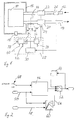
- the intake pipe 12 and an exhaust pipe 14 has.
- the exhaust pipe 14 and the intake pipe 12 are connected to each other by an exhaust gas recirculation line 16.
- an exhaust gas recirculation valve 18 is arranged in the exhaust gas recirculation line 16, with which the flow cross section of the exhaust gas recirculation line can be changed.
- the diesel engine 10 is with a Exhaust gas turbocharger with a turbine arranged in the exhaust line 20 and a compressor arranged in the intake line 22 provided.
- the turbine 20 has a variable turbine geometry on, which are set by means of an actuator 24 can.
- An air mass meter 26 is provided in the intake line 12, the air mass flow flowing through the intake line 12 detected. The measured air mass flow is sent to a Control device 28 pass the control signals for the Actuator 24 of the turbine 20 and for the exhaust gas recirculation valve 18 generated.
- control unit 28 has a controller 30, which as Command variable used the air mass flow in the intake line 12. Depending on a predetermined setpoint and the actual value of the air mass flow detected with the air mass meter 26 controller 30 outputs a manipulated variable. This manipulated variable is further processed in the control unit 28 to generate the control signals for the actuator 24 of the turbine 20 and the control signal to generate for the exhaust gas recirculation valve 18.
- the manipulated variable of controller 30 becomes a limiter on the one hand 32 supplied that the manipulated variable to a minimum or maximum Value limited and then as an actuating signal to the actuator 24 of the turbine 20 outputs.
- the limiter 32 which is the limitation the manipulated variable is variable depending on the current one Load and / or speed state of the diesel engine 10, extreme positions of the turbine 20 are avoided, the one Unacceptable deterioration in turbine 20 efficiency would effect.
- the limiter 32 therefore has the function of a variable stop for the adjustment of the variable turbine geometry the turbine 20.
- the load and / or speed condition supplied to the limiter 32 of the diesel engine 10 is symbolized by the arrow 34.
- the manipulated variable of the controller 30 becomes an inverter 36 fed and inverted there.
- the exhaust gas recirculation valve 18 changes in exhaust gas recirculation mode, the setpoint specification to a new, higher value of the air mass flow, the exhaust gas recirculation valve 18 are closed.
- the turbine 20 is opposed controlled to generate the increased air mass flow.
- the one provided for the actuator 24 of the turbine 20 The manipulated variable is therefore inverted in order to generate it Use control signal for the exhaust gas recirculation valve 18.
- the inversion of the manipulated variable for controlling the Turbine 20 in inverter 36 is only the effective direction of the Actuator 24 and the exhaust gas recirculation valve 18 set.
- the desired ratio of the control signal values for the exhaust gas recirculation valve 18 and the control signal values for the actuator 24 of the turbine 20 is carried out in the function block 38.
- the Function block 38 contains a map in which for each desired Setpoint of the exhaust gas recirculation rate the correct ratio the setting of the turbine 20 to the setting of the exhaust gas recirculation valve 18 across various load and / or speed conditions of the diesel engine 10 is stored.
- the desired Exhaust gas recirculation rate is symbolized by arrow 40 and is supplied to the function block 38 by an engine control.
- the Load and / or speed state of the diesel engine 10 is through symbolizes the arrow 42 and is also from the engine control output. After the control signal in the function block 38 for the exhaust gas recirculation valve 18 in the correct ratio generated to the control signal for the actuator 24 of the turbine 20 it is output to the exhaust gas recirculation valve 18.
- Function block 38 can also make further corrections of the control signal for the exhaust gas recirculation valve 18, for example based on an atmospheric pressure, an air temperature and / or a cooling water temperature of the diesel engine 10.
- the controller 30 is designed as a PI controller, the control characteristic of the controller 30 depending on the operating state of the diesel engine 10 can be changed. So because of the drastically different behavior of the controlled system in exhaust gas recirculation mode compared to the pronounced turbocharger operation the control characteristic between these two operating modes switched. In pronounced turbocharger operation Without exhaust gas recirculation, the controller 30 has aggressive control parameters operated. In contrast, in exhaust gas recirculation mode defensive control parameters used. This can result in turbocharger operation even a high boost pressure is set in a short time to get acceptable mileage one with the diesel engine To reach 10 equipped vehicles. On the other hand, one precise exhaust gas recirculation achieved in exhaust gas recirculation mode.
- a throttle valve shown in dashed lines in the intake line 12 44 can be provided for an expanded pressure drop between exhaust pipe 14 and intake pipe 12.
- the control signal for the throttle valve 44 is also generated on the basis of the manipulated variable of the common controller 30. Also in this case, the controller 30 only outputs a manipulated variable that for setting the exhaust gas recirculation valve 18, the turbine 20 and the throttle valve 44 is used.
- the Actuator 24 for the turbine 20 and the exhaust gas recirculation valve 18 without delay to the specified setpoint assigned setting values.
- one Fuel injection quantity for the diesel engine 10 only increased if existing exhaust gas in the intake line 12 through the Diesel engine 10 was suctioned off. For this purpose, a predetermined Number of work cycles of the internal combustion engine awaited, until the injection quantity is increased. The number of waits Work cycles depend on the volume of the intake line 12.
- a control is shown in the schematic representation of FIG. 2 shown in the device of FIG. 1 with which these measures be made.
- a counter 46 receives from a Switch 48 a signal whether there is an exhaust gas recirculation mode or Not.
- the exhaust gas recirculation valve When accelerating from the exhaust gas recirculation mode, as stated, the exhaust gas recirculation valve is closed, so that switch 48, as shown, is in position EGR-Off and sends a signal to the counter 46 that there is no longer any exhaust gas recirculation mode.
- the counter 46 Via a connection 50, the counter 46 also receives the current speed of the diesel engine 10.
- the counter 46 counts a predetermined number of work cycles of the diesel engine 10, which is required to in the Intake line 12 to suck off existing exhaust gas. Only after expiration the predetermined number of working cycles of the diesel engine 10 the counter 46 gives a corresponding enable signal to one Switching device 52 further.
- the switching device 52 is then used to switch between a previous fuel injection amount by the Block 54 is symbolized, and a new, desired fuel injection amount made on connection 56.
- the at Accelerated set injection quantity is based on an accelerator pedal position on connection 58 and the Speed determined on the connection 50 by means of a map 60. Only after the counted and predetermined by the counter 46 Number of working cycles of the diesel engine 10 takes place is, this counter 46 gives the enable signal to the switching device 52 off, which is a fuel injection quantity from a previous setting 54 to the current target setting switches on connection 56.
Landscapes
- Engineering & Computer Science (AREA)
- Chemical & Material Sciences (AREA)
- Combustion & Propulsion (AREA)
- Mechanical Engineering (AREA)
- General Engineering & Computer Science (AREA)
- Exhaust-Gas Circulating Devices (AREA)
- Output Control And Ontrol Of Special Type Engine (AREA)
Applications Claiming Priority (2)
| Application Number | Priority Date | Filing Date | Title |
|---|---|---|---|
| DE10101343A DE10101343A1 (de) | 2001-01-13 | 2001-01-13 | Verfahren und Vorrichtung zur Abgasrückführungsregelung |
| DE10101343 | 2001-01-13 |
Publications (2)
| Publication Number | Publication Date |
|---|---|
| EP1223320A2 true EP1223320A2 (fr) | 2002-07-17 |
| EP1223320A3 EP1223320A3 (fr) | 2006-07-05 |
Family
ID=7670452
Family Applications (1)
| Application Number | Title | Priority Date | Filing Date |
|---|---|---|---|
| EP01129920A Withdrawn EP1223320A3 (fr) | 2001-01-13 | 2001-12-15 | Méthode et dispositif de recirculation de gaz d'échappement |
Country Status (2)
| Country | Link |
|---|---|
| EP (1) | EP1223320A3 (fr) |
| DE (1) | DE10101343A1 (fr) |
Families Citing this family (3)
| Publication number | Priority date | Publication date | Assignee | Title |
|---|---|---|---|---|
| DE102004044893A1 (de) | 2004-09-14 | 2006-03-30 | Volkswagen Ag | Abgasrückführeinrichtung und Verfahren zum Betrieb einer Abgasrückführeinrichtung |
| DE102009016522A1 (de) * | 2009-04-08 | 2010-10-14 | Man Diesel & Turbo Se | Abgasturbolader-Anordnung mit integrierter Abblaseklappe, damit ausgerüstetes Antriebssystem und Verfahren zum Betreiben eines solchen Antriebssystems |
| DE102016206554B4 (de) * | 2016-04-19 | 2025-10-16 | Schaeffler Technologies AG & Co. KG | Verfahren und Vorrichtung zur Einstellung des Massenstromes eines Abgasrückführventils |
Citations (1)
| Publication number | Priority date | Publication date | Assignee | Title |
|---|---|---|---|---|
| DE19801395A1 (de) | 1998-01-16 | 1999-07-22 | Daimler Chrysler Ag | Vorrichtung zur Ladedruckregelung und Abgasrückführungsregelung bei einer Brennkraftmaschine, insbesondere einem Dieselmotor |
Family Cites Families (6)
| Publication number | Priority date | Publication date | Assignee | Title |
|---|---|---|---|---|
| JPH08270454A (ja) * | 1995-03-30 | 1996-10-15 | Toyota Motor Corp | 可変容量ターボチャージャ |
| NL1000119C2 (nl) * | 1995-04-11 | 1996-10-14 | Tno | Uitlaatgasrecirculatiesysteem voor een inwendige verbrandingsmotor. |
| DE19603591C1 (de) * | 1996-02-01 | 1997-03-06 | Daimler Benz Ag | Abgasrückführung für eine Brennkraftmaschine |
| DE19615545C1 (de) * | 1996-04-19 | 1997-06-12 | Daimler Benz Ag | Einrichtung zur Dieselmotorbetriebsregelung mit Abgasrückführung und Ansaugluftdrosselung |
| JP3430923B2 (ja) * | 1998-06-15 | 2003-07-28 | 日産自動車株式会社 | 内燃機関の過給制御装置 |
| US6128902A (en) * | 1999-01-26 | 2000-10-10 | Ford Global Technologies, Inc. | Control method and apparatus for turbocharged diesel engines having exhaust gas recirculation |
-
2001
- 2001-01-13 DE DE10101343A patent/DE10101343A1/de not_active Withdrawn
- 2001-12-15 EP EP01129920A patent/EP1223320A3/fr not_active Withdrawn
Patent Citations (1)
| Publication number | Priority date | Publication date | Assignee | Title |
|---|---|---|---|---|
| DE19801395A1 (de) | 1998-01-16 | 1999-07-22 | Daimler Chrysler Ag | Vorrichtung zur Ladedruckregelung und Abgasrückführungsregelung bei einer Brennkraftmaschine, insbesondere einem Dieselmotor |
Also Published As
| Publication number | Publication date |
|---|---|
| DE10101343A1 (de) | 2002-07-18 |
| EP1223320A3 (fr) | 2006-07-05 |
Similar Documents
| Publication | Publication Date | Title |
|---|---|---|
| DE19531871C1 (de) | Verfahren zur Regelung des Ladedrucks bei einer mittels eines Abgasturboladers mit verstellbarer Turbinengeometrie aufgeladenen Brennkraftmaschine | |
| DE4343353C2 (de) | Verfahren und Vorrichtung zum Steuern einer Brennkraftmaschine | |
| EP2977596B1 (fr) | Moteur a combustion interne dote d'un dispositif de reglage | |
| DE10329763A1 (de) | Koordinierte Regelung einer elektronischen Drosselklappe und eines Turboladers mit variabler Geometrie in ladedruckverstärkten und stöchiometrisch betriebenen Ottomotoren | |
| WO2003027464A1 (fr) | Procede et dispositif pour actionner au moins un turbocompresseur de moteur a combustion interne | |
| DE102004056894A1 (de) | Verfahren und Vorrichtung zur Regelung des Ladedrucks einer Brennkraftmaschine | |
| DE10219382A1 (de) | Steuerungsvorrichtung für eine Brennkraftmaschine | |
| DE102010043897B4 (de) | Verfahren und Vorrichtung zum Betreiben eines Verbrennungsmotors | |
| WO2000019070A1 (fr) | Procede pour reguler et commander un moteur a combustion interne turbocompresse | |
| EP2606213B1 (fr) | Procédé de réglage du fonctionnement stable d'un turbocompresseur à gaz d'échappement d'un moteur à combustion interne et dispositif correspondant | |
| DE102004003378B4 (de) | Regelungs- und Steuerungsvorrichtung und Regelungs- und Steuerungsverfahren für einen mehrstufigen Turbolader | |
| DE3939754A1 (de) | Verfahren zur regelung des druckes in der ansaugleitung vor den einlassventilen bei einer mittels eines abgasturboladers aufgeladenen luftverdichtenden einspritzbrennkraftmaschine | |
| EP3607194B1 (fr) | Procédé servant à faire fonctionner une machine à combustion interne équipée d'un turbocompresseur à gaz d'échappement à géométrie de turbine variable en tenant compte de la contrepression de gaz d'échappement | |
| DE10340062A1 (de) | Verfahren und Vorrichtung zum Betreiben einer Brennkraftmaschine | |
| DE102009032659A1 (de) | Kombinierte Rauchbegrenzung | |
| DE60215903T2 (de) | Verfahren zur Steuerung eines Abgasturboladers mit verstellbarer Turbinengeometrie | |
| EP1346137B1 (fr) | Dispositif permettant de commander un turbocompresseur a gaz d'echappement et turbocompresseur a gaz d'echappement associe | |
| WO2009040040A1 (fr) | Procédé et dispositif de réglage de la pression d'aspiration d'un moteur à combustion interne | |
| EP1223320A2 (fr) | Méthode et dispositif de recirculation de gaz d'échappement | |
| DE19804466C2 (de) | Verfahren zur Steuerung eines Abgasturboladers mit variabler Turbinengeometrie | |
| DE102010023636B4 (de) | Verfahren zum Betreiben eines Antriebsaggregats | |
| DE10234719B3 (de) | Verfahren zur Füllungsregelung einer Brennkraftmaschine | |
| EP1672203B1 (fr) | Procédé et dispositif de commande d'un moteur à combustion interne dans un véhicule | |
| DE102005023260A1 (de) | Verfahren zur Regelung eines Abgasturboladers | |
| DE69821281T2 (de) | Steuerung für Dieselmotor. |
Legal Events
| Date | Code | Title | Description |
|---|---|---|---|
| PUAI | Public reference made under article 153(3) epc to a published international application that has entered the european phase |
Free format text: ORIGINAL CODE: 0009012 |
|
| AK | Designated contracting states |
Kind code of ref document: A2 Designated state(s): AT BE CH CY DE DK ES FI FR GB GR IE IT LI LU MC NL PT SE TR |
|
| AX | Request for extension of the european patent |
Free format text: AL;LT;LV;MK;RO;SI |
|
| PUAL | Search report despatched |
Free format text: ORIGINAL CODE: 0009013 |
|
| AK | Designated contracting states |
Kind code of ref document: A3 Designated state(s): AT BE CH CY DE DK ES FI FR GB GR IE IT LI LU MC NL PT SE TR |
|
| AX | Request for extension of the european patent |
Extension state: AL LT LV MK RO SI |
|
| STAA | Information on the status of an ep patent application or granted ep patent |
Free format text: STATUS: THE APPLICATION IS DEEMED TO BE WITHDRAWN |
|
| 18D | Application deemed to be withdrawn |
Effective date: 20060701 |