EP1223332A2 - Dispositif de chauffage et méthode d'opération - Google Patents
Dispositif de chauffage et méthode d'opération Download PDFInfo
- Publication number
- EP1223332A2 EP1223332A2 EP01118880A EP01118880A EP1223332A2 EP 1223332 A2 EP1223332 A2 EP 1223332A2 EP 01118880 A EP01118880 A EP 01118880A EP 01118880 A EP01118880 A EP 01118880A EP 1223332 A2 EP1223332 A2 EP 1223332A2
- Authority
- EP
- European Patent Office
- Prior art keywords
- air
- collector
- heating
- intake
- engine
- Prior art date
- Legal status (The legal status is an assumption and is not a legal conclusion. Google has not performed a legal analysis and makes no representation as to the accuracy of the status listed.)
- Withdrawn
Links
- 238000010438 heat treatment Methods 0.000 title claims abstract description 266
- 238000000034 method Methods 0.000 title claims description 19
- 239000000446 fuel Substances 0.000 claims description 216
- 239000000203 mixture Substances 0.000 claims description 85
- QVGXLLKOCUKJST-UHFFFAOYSA-N atomic oxygen Chemical compound [O] QVGXLLKOCUKJST-UHFFFAOYSA-N 0.000 claims description 65
- 229910052760 oxygen Inorganic materials 0.000 claims description 65
- 239000001301 oxygen Substances 0.000 claims description 65
- 238000002485 combustion reaction Methods 0.000 claims description 33
- 239000007789 gas Substances 0.000 claims description 30
- 238000011144 upstream manufacturing Methods 0.000 claims description 12
- 238000002156 mixing Methods 0.000 claims description 6
- 239000003570 air Substances 0.000 description 191
- 238000002347 injection Methods 0.000 description 18
- 239000007924 injection Substances 0.000 description 18
- 238000010276 construction Methods 0.000 description 11
- 238000010586 diagram Methods 0.000 description 9
- 239000004215 Carbon black (E152) Substances 0.000 description 8
- 229930195733 hydrocarbon Natural products 0.000 description 8
- 150000002430 hydrocarbons Chemical class 0.000 description 8
- 230000005855 radiation Effects 0.000 description 8
- 230000003197 catalytic effect Effects 0.000 description 7
- 239000000835 fiber Substances 0.000 description 7
- 239000002826 coolant Substances 0.000 description 6
- 239000004065 semiconductor Substances 0.000 description 6
- 229920003002 synthetic resin Polymers 0.000 description 6
- 239000000057 synthetic resin Substances 0.000 description 6
- PNEYBMLMFCGWSK-UHFFFAOYSA-N aluminium oxide Inorganic materials [O-2].[O-2].[O-2].[Al+3].[Al+3] PNEYBMLMFCGWSK-UHFFFAOYSA-N 0.000 description 5
- 230000020169 heat generation Effects 0.000 description 5
- 238000000889 atomisation Methods 0.000 description 4
- 230000006698 induction Effects 0.000 description 4
- 229910052751 metal Inorganic materials 0.000 description 4
- 239000002184 metal Substances 0.000 description 4
- 229920005989 resin Polymers 0.000 description 4
- 239000011347 resin Substances 0.000 description 4
- XEEYBQQBJWHFJM-UHFFFAOYSA-N Iron Chemical compound [Fe] XEEYBQQBJWHFJM-UHFFFAOYSA-N 0.000 description 3
- 229910052782 aluminium Inorganic materials 0.000 description 3
- XAGFODPZIPBFFR-UHFFFAOYSA-N aluminium Chemical compound [Al] XAGFODPZIPBFFR-UHFFFAOYSA-N 0.000 description 3
- 239000012080 ambient air Substances 0.000 description 3
- 239000010949 copper Substances 0.000 description 3
- 239000003822 epoxy resin Substances 0.000 description 3
- 230000005669 field effect Effects 0.000 description 3
- 238000004519 manufacturing process Methods 0.000 description 3
- 230000002093 peripheral effect Effects 0.000 description 3
- BASFCYQUMIYNBI-UHFFFAOYSA-N platinum Substances [Pt] BASFCYQUMIYNBI-UHFFFAOYSA-N 0.000 description 3
- 229920000647 polyepoxide Polymers 0.000 description 3
- 238000010926 purge Methods 0.000 description 3
- 229910000838 Al alloy Inorganic materials 0.000 description 2
- 230000005540 biological transmission Effects 0.000 description 2
- 238000001816 cooling Methods 0.000 description 2
- 229910052802 copper Inorganic materials 0.000 description 2
- 239000003365 glass fiber Substances 0.000 description 2
- 238000009434 installation Methods 0.000 description 2
- 239000012212 insulator Substances 0.000 description 2
- 229910052742 iron Inorganic materials 0.000 description 2
- 229910052697 platinum Inorganic materials 0.000 description 2
- -1 polyethylene terephthalate Polymers 0.000 description 2
- 229920000642 polymer Polymers 0.000 description 2
- 230000001737 promoting effect Effects 0.000 description 2
- HBMJWWWQQXIZIP-UHFFFAOYSA-N silicon carbide Chemical compound [Si+]#[C-] HBMJWWWQQXIZIP-UHFFFAOYSA-N 0.000 description 2
- 238000004513 sizing Methods 0.000 description 2
- XLYOFNOQVPJJNP-UHFFFAOYSA-N water Substances O XLYOFNOQVPJJNP-UHFFFAOYSA-N 0.000 description 2
- 229920000049 Carbon (fiber) Polymers 0.000 description 1
- RYGMFSIKBFXOCR-UHFFFAOYSA-N Copper Chemical compound [Cu] RYGMFSIKBFXOCR-UHFFFAOYSA-N 0.000 description 1
- 229910000861 Mg alloy Inorganic materials 0.000 description 1
- 239000004677 Nylon Substances 0.000 description 1
- 229930182556 Polyacetal Natural products 0.000 description 1
- QCWXUUIWCKQGHC-UHFFFAOYSA-N Zirconium Chemical compound [Zr] QCWXUUIWCKQGHC-UHFFFAOYSA-N 0.000 description 1
- 230000003213 activating effect Effects 0.000 description 1
- 238000007792 addition Methods 0.000 description 1
- JRPBQTZRNDNNOP-UHFFFAOYSA-N barium titanate Chemical compound [Ba+2].[Ba+2].[O-][Ti]([O-])([O-])[O-] JRPBQTZRNDNNOP-UHFFFAOYSA-N 0.000 description 1
- 229910002113 barium titanate Inorganic materials 0.000 description 1
- 238000005452 bending Methods 0.000 description 1
- 239000004917 carbon fiber Substances 0.000 description 1
- 230000015556 catabolic process Effects 0.000 description 1
- 239000000919 ceramic Substances 0.000 description 1
- 230000001609 comparable effect Effects 0.000 description 1
- 238000006731 degradation reaction Methods 0.000 description 1
- 238000001514 detection method Methods 0.000 description 1
- 238000003745 diagnosis Methods 0.000 description 1
- 230000000694 effects Effects 0.000 description 1
- 230000003028 elevating effect Effects 0.000 description 1
- 238000007710 freezing Methods 0.000 description 1
- 230000008014 freezing Effects 0.000 description 1
- 239000002828 fuel tank Substances 0.000 description 1
- 230000005484 gravity Effects 0.000 description 1
- 229910052749 magnesium Inorganic materials 0.000 description 1
- 239000011777 magnesium Substances 0.000 description 1
- 229910052748 manganese Inorganic materials 0.000 description 1
- 239000011572 manganese Substances 0.000 description 1
- 238000005259 measurement Methods 0.000 description 1
- VNWKTOKETHGBQD-UHFFFAOYSA-N methane Chemical compound C VNWKTOKETHGBQD-UHFFFAOYSA-N 0.000 description 1
- 229910052750 molybdenum Inorganic materials 0.000 description 1
- 229910052759 nickel Inorganic materials 0.000 description 1
- PXHVJJICTQNCMI-UHFFFAOYSA-N nickel Substances [Ni] PXHVJJICTQNCMI-UHFFFAOYSA-N 0.000 description 1
- 229920001778 nylon Polymers 0.000 description 1
- 230000003287 optical effect Effects 0.000 description 1
- 238000004806 packaging method and process Methods 0.000 description 1
- 229920001707 polybutylene terephthalate Polymers 0.000 description 1
- 229920000139 polyethylene terephthalate Polymers 0.000 description 1
- 239000005020 polyethylene terephthalate Substances 0.000 description 1
- 239000002861 polymer material Substances 0.000 description 1
- 229920006324 polyoxymethylene Polymers 0.000 description 1
- 238000000746 purification Methods 0.000 description 1
- 230000002787 reinforcement Effects 0.000 description 1
- 238000004904 shortening Methods 0.000 description 1
- 229910052710 silicon Inorganic materials 0.000 description 1
- 239000010703 silicon Substances 0.000 description 1
- 125000006850 spacer group Chemical group 0.000 description 1
- 229920005992 thermoplastic resin Polymers 0.000 description 1
- 229910052721 tungsten Inorganic materials 0.000 description 1
- 238000009423 ventilation Methods 0.000 description 1
- 239000002918 waste heat Substances 0.000 description 1
- 229910052725 zinc Inorganic materials 0.000 description 1
- 239000011701 zinc Substances 0.000 description 1
- 229910052726 zirconium Inorganic materials 0.000 description 1
Images




Classifications
-
- F—MECHANICAL ENGINEERING; LIGHTING; HEATING; WEAPONS; BLASTING
- F02—COMBUSTION ENGINES; HOT-GAS OR COMBUSTION-PRODUCT ENGINE PLANTS
- F02M—SUPPLYING COMBUSTION ENGINES IN GENERAL WITH COMBUSTIBLE MIXTURES OR CONSTITUENTS THEREOF
- F02M31/00—Apparatus for thermally treating combustion-air, fuel, or fuel-air mixture
- F02M31/02—Apparatus for thermally treating combustion-air, fuel, or fuel-air mixture for heating
-
- Y—GENERAL TAGGING OF NEW TECHNOLOGICAL DEVELOPMENTS; GENERAL TAGGING OF CROSS-SECTIONAL TECHNOLOGIES SPANNING OVER SEVERAL SECTIONS OF THE IPC; TECHNICAL SUBJECTS COVERED BY FORMER USPC CROSS-REFERENCE ART COLLECTIONS [XRACs] AND DIGESTS
- Y02—TECHNOLOGIES OR APPLICATIONS FOR MITIGATION OR ADAPTATION AGAINST CLIMATE CHANGE
- Y02T—CLIMATE CHANGE MITIGATION TECHNOLOGIES RELATED TO TRANSPORTATION
- Y02T10/00—Road transport of goods or passengers
- Y02T10/10—Internal combustion engine [ICE] based vehicles
- Y02T10/12—Improving ICE efficiencies
Definitions
- the present invention relates to a novel heating device, a drive method and a device of an engine, an air intake module for an internal combustion engine or a member thereof.
- heating devices are used widely. Such heating device is often controlled by a control unit so that a heating object can be maintained within a predetermined temperature range.
- a control unit there is a heater for an oxygen sensor as disclosed in Japanese Patent Application Laid-Open No. Heisei 10 -332628(1999).
- a current flowing through the heating device (heater) is controlled ON and OFF at a predetermined duty cycle by the control unit to prevent excessive heating of the heating device (heater) for protecting oxygen sensor and quickly activating the oxygen sensor by elevating temperature thereof.
- U. S. Patent No. 5,894,832 discloses a cold start device for reducing hydrocarbon (HC) in an exhaust gas by heating an air/fuel mixture.
- Japanese Patent Application Laid-Open No. Heisei 6-231807(1994) discloses a battery heating device having a having a heating device provided with a transmission means for transmitting a waste heat of a combustion heater to the battery.
- Japanese Patent Application Laid-Open No. Heisei 3-70625(1991) discloses transmission of heating generated by power loss of a blower motor control transistor of an automotive humidifier to a heat radiation plate within a vessel.
- a fuel heater forming a cold start device is heated by a heater switch driver and a heater switch controlled by an engine control unit (ECU).
- ECU engine control unit
- amount of heat generated in the header switch driver and the heater switch becomes significant.
- by replacing the heater switch with an electronic element (current control element) longer life can be attained.
- heat generation amount of the current control element becomes large to require large heat radiator for radiating generated heat.
- the heat generated by the current control element is wastefully radiated to the ambient air.
- the present invention has been worked out the shortcoming in the prior art. Therefore, it is an object of the present invention to provide a heating device, in which a current control element controlling a current flowing through a heater body forming a heating device is thermally coupled with a heat conductive body together with the heater body for transmitting heat generated by both of the heater body and the current control element to the heat conductive body to efficiently heat a heated body as heating object.
- a heating device comprises:
- a drive method for an engine branching an intake air to be supplied to a collector across an air adjusting valve into a plurality of intake air passage in an intake manifold for supplying into each engine cylinder, injecting fuel into intake air flow for driving the engine comprises steps of:
- a drive method for an engine branching an intake air to be supplied to a collector across an air adjusting valve into a plurality of intake air passage in an intake manifold for supplying into each engine cylinder, injecting fuel into intake air flow for driving the engine, and detecting oxygen concentration in an exhaust gas by means of an oxygen sensor comprises steps of:
- an engine driving system branching an intake air to be supplied to a collector across an air adjusting valve into a plurality of intake air passage in an intake manifold for supplying into each engine cylinder, injecting fuel into intake air flow for driving the engine, the system comprises:
- an engine driving system branching an intake air to be supplied to a collector across an air adjusting valve into a plurality of intake air passage in an intake manifold for supplying into each engine cylinder, injecting fuel into intake air flow for driving the engine, the system comprises:
- an engine driving system branching an intake air to be supplied to a collector across an air adjusting valve into a plurality of intake air passage in an intake manifold for supplying into each engine cylinder, injecting fuel into intake air flow for driving the engine, and detecting oxygen concentration in an exhaust gas by means of an oxygen sensor, the system comprises:
- an air intake module for an internal combustion engine comprises:
- an air intake module for an internal combustion engine comprises :
- an air intake module for an internal combustion engine including an intake manifold having air intake passages arranged in parallel to a collector comprises:
- an air intake module for an internal combustion engine including an intake manifold having air intake passages arranged in parallel to a collector, the collector or the intake manifold having a polygonal section perpendicular to a longitudinal direction with a plurality of planar surface in part.
- a cold start device for an internal combustion engine comprises:
- an engine driving system branching an intake air to be supplied to a collector across an air adjusting valve into a plurality of intake air passage in an intake manifold for supplying into each engine cylinder, injecting fuel into intake air flow for driving the engine, the system comprises:
- an engine driving system branching an intake air to be supplied to a collector across an air adjusting valve into a plurality of intake air passage in an intake manifold for supplying into each engine cylinder, injecting fuel into intake air flow for driving the engine, and detecting oxygen concentration in an exhaust gas by means of an oxygen sensor, the system comprises:
- a drive method for an engine branching an intake air to be supplied to a collector across an air adjusting valve into a plurality of intake air passage in an intake manifold for supplying into each engine cylinder, injecting fuel into intake air flow for driving the engine, and detecting oxygen concentration in an exhaust gas by means of an oxygen sensor, the method for driving the engine in cold start condition, comprises steps of:
- an engine driving system branching an intake air to be supplied to a collector across an air adjusting valve into a plurality of intake air passage in an intake manifold for supplying into each engine cylinder, injecting fuel into intake air flow for driving the engine, the system being active at cold starting of the engine, comprising:
- an engine driving system branching an intake air to be supplied to a collector across an air adjusting valve into a plurality of intake air passage in an intake manifold for supplying into each engine cylinder, injecting fuel into intake air flow for driving the engine, the system being active at cold starting of the engine, comprises:
- an engine driving system branching an intake air to be supplied to a collector across an air adjusting valve into a plurality of intake air passage in an intake manifold for supplying into each engine cylinder, injecting fuel into intake air flow for driving the engine, and detecting oxygen concentration in an exhaust gas by means of an oxygen sensor, the system being active at cold starting of the engine, comprises :
- an air intake module for an internal combustion engine comprises:
- the collector in the air intake module for the internal combustion engine, is provided with a tilted portion tilted at an angle greater than or equal to 45° in upward direction on the side of the electronically controlled throttle assembly.
- a diameter of the diameter of the titled portion is smaller than a diameter on the side of the intake manifold.
- the collector and the intake manifold are formed with a fiber reinforced synthetic resin.
- the intake manifold is integrated by partial fitting.
- the intake manifold is at least separated into two segments on the engine side and the collector side.
- the collector and the portion of the intake manifold on the side of the collector are formed with fiber reinforced synthetic resin, and the portion of the intake manifold on the side of the engine is preferably formed with aluminum diecast.
- heat generated by the current control element is transmitted through the heat conductive body to be transmitted to the heating object together with heat generated by the heating body. Since heat generated by the current control element is transferred to the heating object, it becomes unnecessary to provide particular heat radiator for the current control element.
- Fig. 1 is a block diagram showing a construction of a heating device according to the present invention.
- a heating body 1 is electrically controlled to a power source 5 via a current control element 4.
- the current control element 4 controls a current flowing through the heating body 1 on the basis of a control signal line 6.
- the heating body 1 and the current control element 4 are thermally coupled with a heat conductive body 2.
- the heat conductive body 2 is thermally coupled with a heating object 3. Namely, the heating body 1 and the current control element 4 are thermally coupled to the heating object 3 via the heat conductive body 2.
- the heat generated by the current control element 4 wastefully radiated to the environment in the prior art can be used in heating the heating object 3 to result in effective use of energy. Furthermore, it does not require heat radiator for radiating the heat of the current control element 4 to permit simplification of the control unit.
- Fig. 2 is a block diagram showing an embodiment, in which a field effect transistor is employed as the current control element 4.
- a field effect transistor is employed as the current control element 4.
- bipolar transistor, thyristor, magnetic amplifier and so forth may also be used as the current control element 4.
- processes has to be selectively used depending upon target heating temperatures of the heating object.
- target heating temperatures of the heating object For example, in case of the field effect transistor, when the target heating temperature is lower than or equal to 150 °C to 175 °C, normal bulk process can be used. When the target heating temperature is in a range between about 150 °C to about 225 °C, SOI (silicon on insulator) process is used. When the target heating temperature is higher than about 225 °C, silicon carbide (SiC) process can be used.
- SiC silicon carbide
- Fig. 3 is a block diagram for controlling the current control element 4 by a control signal output from a control unit 8 having a control function 7 and fed through a control signal line 6.
- heat generated by the current control element 4 which has been wastefully radiated to the environment conventionally, can be used for heating the heating object 3 to improve energy use efficiency.
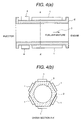
- Figs. 4(a) and 4(b) are front elevation and section of a construction applied the heating device according to the present invention to an air intake pipe of an automotive vehicle, as a cold start device, in which Fig. 4(a) is a front elevation and Fig. 4(b) is a section taken along line A - A of Fig. 4(a).
- the cold start device is a device for promoting vapor of fuel by heating the air intake pipe immediately after an injector (fuel injection valve) immediately after starting up of the engine and under cold condition of the air intake system, and preventing discharge of unburnt exhaust gas (hydrocarbon: HC) due to adhering of fuel on a peripheral wall.
- the cold start device is constructed by fitting heating bodies 1 on each planar surfaces of a portion of the air take pipe which portion is formed into hexagonal shape with a heat conductive body 2. Furthermore, by the present invention, the current control element 4 is fitted on a portion of the air intake pipe formed with the heat conductive body 2.
- the air intake pipe is formed with a metal, such as iron, aluminum, magnesium alloy or the like as conventionally known in the art. Since such metallic air intake pipe has high thermal conductivity coefficient and thus can be used as heat conductive body 2 as is. Since study of high polymer is in progress, when heat conductive high polymer is put into practice, heat conductive high polymer material may be preferred for better forming ability and workability.
- the cold start device is constructed by forming a portion of the air intake pipe as heat conductive body into a polyhedral shape and fitting the heating body 1 and the current control element 4 on each planar surfaces of the polyhedral body.
- the heating body not only heat generated by the heating body but also heat generated by the current control element 4 are transmitted to the heating object, air/fuel mixture in the shown case, to effectively use heat of the heating body 1 and the current control element 4 for heating the heating object 3 (air/fuel mixture).
- operation temperature of the current control element 4 can be lowered to permit implementation of the present invention without requiring special process for high temperature operation, such as SIO or the like as set forth above.
- Fig. 5 is a section of the heating body 1.
- the heating body 1 is formed by forming electrodes 20 of a heat resistive metal film, such as Mo, W, Pt or the like on a quadrangular surface of a sintered resistor body 21 of barium titanate, and entire surface is covered with an alumina film.
- a lead terminal for externally supplying power source is connected to the electrode 20 to the electrode 20 to the electrode 20.
- Fig. 6 is a section of the current control element.
- a semiconductor element 23 is fitted on a copper heat radiation plate 24 through an insulator, and then sealed with an epoxy resin 22.
- a pre-assembly of the semiconductor element 23, the heat radiation plate 24 and the epoxy resin 22 is mounted on a heat conductive body 2.
- the current control element bipolar transistor, power MOSFET or the like are used.
- the head conductive body 2 may serve as replacement for the heat radiation plate for effectively using thermal energy.
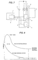
- Fig. 7 is a block diagram of the fifth embodiment, in which, in addition to the current control element 4 for controlling a current for the heating body 1, a current control element 4' controlling a current for a heating body 1' is also thermally coupled with the heat conductive body 2 and the head conductive body 2 is thermally coupled with the heating object 3.
- a current control element 4' controlling a current for a heating body 1' is also thermally coupled with the heat conductive body 2 and the head conductive body 2 is thermally coupled with the heating object 3.
- the shown embodiment not only heat generated by the current control element 4 but also heat generated by the current control element 4' may be used for heating the heating object 3 to further improve energy using efficiency.
- the shown construction may achieve particularly good effect to use the heating device constructed with the heating body 1 and the heat conductive body 2 as the cold start device as set forth above, and to use the heating body 1' as an oxygen sensor heater.
- supply current namely heat generation amount of the cold start device and the oxygen sensor heater are both become maximum immediately after starting up of the engine in cold engine condition. Accordingly, immediately after cold starting of the engine, heat generation amount of the current control element 4 and the current control element 4' also become maximum. Comparable effect may also be obtained even when the heating device constituted of the heating body 1 and the head conductive body, is used as the oxygen sensor heater and the heating body 1' is used as the cold start device. In such case, immediately after starting up of the engine in cold engine condition, heat generation amount of the current control element 4 and the current control element 4' becomes maximum to efficiently heat the oxygen sensor as heating object 3.
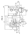
- Fig. 9 shows an overall construction of a particular internal combustion engine, in which the cold start device according to the present invention is applied.
- An intake manifold 410 is connected to one end of an air intake supplying an intake air as indicated by arrow on the left side in Fig. 9.
- An air cleaner (not shown) may be provided in the air intake.
- a mass air flow sensor 4 is disposed within an air intake passage 422 defined in the air intake.
- a throttle valve 409 is provided within the air intake passage 422.
- the throttle valve 409 is rotatably supported on a throttle shaft.
- a throttle valve angular position is detected by a throttle position sensor 416.
- the throttle valve 409, the throttle shaft and the throttle position sensor 416 are generally referred to as throttle assembly.
- An idle air passage 401a is communicated with the air intake passage 422 at a position between the mass air flow sensor 408b and the throttle assembly, for introducing part of the intake air into a cold start device 1.
- intake air to be introduced into the intake manifold 410 is mixed with fuel injected from a fuel injection valve 401d in the cold start device 401, and under engine operating condition other than cold start condition, fuel is injected by a multi-port fuel injection valve 402.
- exhaust gas is discharged from combustion chambers 414 through an exhaust passage via a lambda type O 2 sensor 412 and a catalytic converter 407.
- an exhaust temperature sensor 425 is provided at upstream side of the catalytic converter 407 disposed in the exhaust passage for measuring a temperature of exhaust gas discharged from the combustion chambers 414.
- the engine control unit (ECU) 3 monitors operating condition of the engine by various sensors, such as the mass air flow sensor 4, the throttle position sensor 416, a crank angle sensor 411, the O 2 sensor, the exhaust temperature sensor 425, an engine coolant temperature sensor 413 mounted in an engine jacket, a ammeter 418 connected to a battery 417 and so forth.
- sensors such as the mass air flow sensor 4, the throttle position sensor 416, a crank angle sensor 411, the O 2 sensor, the exhaust temperature sensor 425, an engine coolant temperature sensor 413 mounted in an engine jacket, a ammeter 418 connected to a battery 417 and so forth.
- the ECU 3 uses sensor input for feedback control of the engine. For example, the ECU 3 controls pulse signal to be fed to the fuel injection valve 401d in the cold start device 401 or the fuel injection valve 402 for controlling a fuel supply amount to the intake manifold.
- the ECU 3 also controls trigger timing of ignition plugs 404 through an ignition module 406 and a distributor 405.
- the ECU 3 further controls operation of a heater switch 419 for supply current to the heater of the cold start device 401.
- the heater switch 419 is a mechanically operable switch, such as relay, solenoid or the like. However, the heater switch 419 may be constructed with a semiconductor switch. In the preferred embodiment, the semiconductor switch having peak current at about 300A and current in a range of 80 to 100A in steady state.
- the cold start device 401 includes a casing including the fuel injection valve 401d having a fuel inlet or an orifice. Idle air introduced through the idle air passage 401a branched from the air intake passage, is introduced at a controlled amount by an idle speed control valve 401b and is then introduced into an idle air mixer 401c to be mixed with the fuel injection valve 401d at the outlet or orifice to form air/fuel mixture. Fuel thus injected from the fuel injection valve 401d is promoted atomization as mixed with the idle air.
- Air/fuel mixture thus formed flows into the intake manifold the heating body 1 and the current control element 4.
- the heating body 1 is formed into a cylindrical shape.
- the heating body 1 may be formed by arranging a plurality of individual heater segments on the outer periphery. Air/fuel mixture flowing through the heating body 1 and the current control element 4 is heated at a temperature in a range of 120 to 200 °C to be further promoted atomization for complete atomization. Air/fuel mixture is then introduced into the combustion chamber 414.
- the heating body 1 and the current control element 4 are constructed in a construction set forth in connection with the first to fifth embodiments.
- Fig. 10 is a constructional illustration of an engine control system, in which the heating device is provided on the oxygen sensors for intake system and exhaust system of the engine. Air introduced into the air intake system via an air cleaner 10 and a throttle valve 11 is mixed with fuel injected through a group of fuel injection valves 12a to 12d each adapted for fuel injection for each individual combustion chamber in the engine for forming air/fuel mixture. Then, air/fuel mixture is introduced into each combustion chamber in the engine 15 through corresponding intake port. While the shown embodiment is directed to four-cylinder engine, the invention is also applicable for engines having n in number of cylinders. In such case, n in number of fuel injection valves are to be provided.
- Air/fuel mixture thus introduced into respective combustion chambers of the engine 15 is burnt therein, and exhaust gas resulting from burning of the mixture is discharged through exhaust ports.
- Exhaust gas flows through the exhaust passage across an oxygen sensor 16, a catalytic converter 18 and a not shown muffler to be discharged into ambient air.
- the oxygen sensor 16 is designed to monitor oxygen concentration in exhaust gas and provides oxygen concentration indicative signal representative of air/fuel ratio and is used for feedback control ( ⁇ control) of fuel injection amount.
- ⁇ control for diagnosis of catalytic converter 18
- another oxygen sensor 17 may be provided at downstream side of the catalytic converter 18 as shown in Fig. 10.
- the heating body 1 includes a plurality of the heating devices 14, each formed into quadrangular shape and are directly fitted on a portion of the air intake passage downstream of the throttle valve 11 connected to a collector together with the current control element 4.
- the current control element 4 turns ON and OFF current to be supplied to the heating bodies 1 forming the heating device (cold start device) 14, at a predetermined duty cycle on the basis of a command from the control unit 8 through the control signal line 6 for controlling current flowing through the oxygen sensor heaters 16 and 17 and whereby controlling amount of heat to be generated. It should be noted that, in the embodiment set forth above, wiring connecting between the power source 5 and the current control elements 4 and 4' and between the heating bodies 1 and 1' and the power source 5 are eliminated from illustration.
- the current control element 4 is constructed with the semiconductor device shown in Fig. 6.
- an air intake module for internal combustion engine in the preferred embodiment is formed with not only parts of air induction system but also a part of fuel system, ECU 260, various harnesses in electric system, into one module (concentrating and forming into a unit) as much as possible for contributing rationalization of automotive vehicle assembling operation, rationalization of transportation, down-sizing, improvement installation ability, lowering of manufacturing cost, lowering of resistance of wire harnesses, and lowering of noise.
- ECU 260 various harnesses in electric system
- An intake manifold 202 (202a to 202a) and a collector (not shown) are integrally molded with a fiber reinforced synthetic resin containing glass fiber having superior heat resistance and mechanical strength in a range of 20 to 40 Wt%, preferably about 30 Wt%.
- synthetic resin thermoplastic resin, such as epoxy resin, polyacetal resin, nylon resin, polyethylene terephthalate resin, polybutylene terephthalate resin and the like may be used.
- reinforcement fiber may be not only glass fiber but also ceramic fiber, metal fiber, carbon fiber and so forth.
- the intake manifold 202 is preferably formed by aluminum diecast with aluminum alloy corresponding to ADC12 under JIS standard. Aluminum alloy containing Si in amount of 4.5 to 13.0 % by weight and one of Cu, Mg, Zn, Fe, Mn, Ni in amount of 0.5 % by weight or Cu in amount of 1.0 to 4.0 % by weight may be used.
- the intake manifolds 202 of fiber reinforced synthetic resin is formed with flanges 314 having greater thickness of the wall of the main body, on the side of the collector. A connecting portion of the intake manifold 202 is connected to a flange having greater thickness of the wall of the main body of the collector through rubber connection pipes 204 fixed to respective flanges via spacer by metal bands 318.
- the air intake module is not specified to the shown construction but can be of various other construction.
- the air intake module disclosed in U. S. Patent No. 6,263,850 may be applicable.
- the disclosure of the above-identified U. S. Patent will be incorporated by reference for the sake of disclosure.
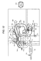
- Fig. 12 is a partial section of the engine system illustrated in Fig. 10 to which the air intake module for an automotive internal combustion engine employing the heating device according to the present invention.
- the heating body 1 and the current control element 4 according to the present invention is provided on the side of the electronically controlled throttle device at the inlet of the collector, as shown in Fig. 11.
- the engine block 100 has a plurality of cylinders 110 but only one cylinder is shown for the purpose of illustration.
- the reference numeral 202 denotes an independent air intake pipes forming the intake manifold. While only one air intake pipe 202 is shown, the intake manifold is constructed with a plurality of independent air intake pips of the number corresponding to number of the engine cylinders. Each independent air intake pipes 202 has a variable air intake value 281 actuated to open and close by a vacuum diaphragm 280.
- the engine control unit (ECU) 260 outputs a signal for switching a three-way solenoid 282 for controlling vacuum applied on the vacuum diaphragm 280 to actuate the variable air intake valve 281 for adjusting air intake path length adapting load condition of the engine.
- the reference numeral 203 denotes the collector (surge tank) located upstream side of the intake manifold, 300 denotes an electronically controlled throttle assembly.
- a throttle position sensor (hereinafter referred to as TPS) 304 for detecting open degree of the throttle valve is build-in as measuring system.
- an air flow meter (hereinafter referred to as AFM) 302 is provided for detecting an intake air flow rate.
- a motor 310 and a gear 311 for controlling opening and closing the throttle valve.
- the independent air intake pipes 202 are branched from the collector 203 and connected to intake ports of the engine cylinders 110. Intake air introduced into the air intake passage through not shown air cleaner is controlled flow rate thereof by the electronically controlled throttle assembly 300. Then, intake air reaches the collector 203 and then introduced into the engine cylinder in suction stroke through the independent air intake pipe 202 of the intake manifold.
- a fuel injector (fuel injection valve)250 is arranged in the vicinity of intake port of the cylinder 100 for injecting fuel toward the intake valve based on the control signal from ECU 260. To the injector 250, fuel is supplied through a fuel gallery (fuel supply pipe) 251.
- independent ignition type ignition coil 104 is directly connected to an ignition plug 120 installed in the engine cylinder.
- the independent ignition type ignition coil 104 is installed within a plug hole and is coupled with an igniter unit (ignition driver circuit) 101. Spark ignition signal is directly set from the ECU time identifier to the igniter unit 101 for controlling spark ignition.
- Sensors for providing control parameters for the ECU includes a crank angle sensor 110, a knock sensor for detecting knocking condition of the engine, cam angle sensor 113, an O 2 sensors 115 and 116 provided in an exhaust passage 114.
- the O 2 sensors 115 and 116 are adapted to detect O 2 concentration in the exhaust gas to output feedback signal for air/fuel ratio control.
- by providing the O 2 sensors at both of upstream and downstream sides of the catalytic converter degradation of exhaust gas purification performance of the catalytic converter can be detected.
- An engine coolant temperature sensor 253 is a sensor for detecting a temperature of the engine coolant. Detection signals of these sensors and AFM are input to ECU 260 through wire harnesses. ECU 260 has functions for deriving fuel supply amount, spark ignition timing or the like on the basis of various measurement signals and sensor signals.
- a part of the engine coolant flows through a passage provided in a throttle body through a hot water piping for preventing the throttle valve or the like from freezing.
- High temperature water (engine coolant) is returned to an engine cooling portion via a reservoir tank and a return pipe.
- a canister 119 is designed for collecting evaporated gas of a fuel tank. Evaporated gas collected by the canister 119 is fed to the collector 203 through a canister purge valve 317 and a canister purge pipe. The canister purge valve 317 is also controlled by the ECU 260.
- PCV valve 322 a crankcase emission control system (hereinafter referred to as Positive Crankcase Ventiration (PCV) valve) is used as PCV valve 322, and a fresh air feeding opening are provided.
- the PCV valve feeds back blow-by gas sucked from the cylinder head cover or a crank case to induction system.
- PCV valve to be controlled path area thereof by manifold vacuum pressure is used. Blow-by gas is fed to downstream side of the throttle valve depending upon the engine load (intake air flow rate). At this time, fresh air is fed trough the fresh air feeding opening and hose connected thereto from the induction system at upstream side of the throttle valve for ventilation of cylinder head cover or crank case.
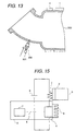
- Fig. 13 is a section of an injector, the heating device and the collector on the side of an electronically controlled throttle assembly of an embodiment of the present invention.
- the collector 203 on the side of the electronically controlled throttle assembly 300 is upwardly curved as shown in Fig. 13 and is tilted about 56° with respect to the center axis of the electronically controlled throttle assembly 300.
- position to exert the weight of the electronically controlled throttle assembly 300 and installation position of the motor in heavy weight can be shifted to gravity center toward lower side to reduce weight load for contributing for reduction of weight.
- wiring and connector may be concentrated on the same side to permit down-sizing of the overall construction.
- the injector 250, the foregoing heating body 1 and the current control element 4 are provided on a portion formed in polyhedral shape as shown in Fig. 4.
- the injector 250 is provided on the side where the electronically controlled throttle assembly 300 is mounted.
- Aportion of the collector 203 where the heating body 1 and the current control element 4 are provided is formed into polyhedral shape in hexagonal shape.
- a plurality of heating devices 1 and the current control element 4 are provided.
- the inlet of the collector 203 may be in straight construction without tilting the inlet. As these heating devices 1 and the current control element 4, those shown in Figs. 5 and 6 are used.
- the peripheral wall of the collector 203 is used in place of the heating body 2.
- air/fuel mixture is heated at a temperature in a range of 120 to 200 °C by the heating devices 1 and the current control element 4.
- the current control element 4 is constructed with SOI.
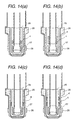
- Figs. 14(a), 14(b), 14(c) and 14(d) are sections of the oxygen sensor having the heating bodies 1 and the current control element 4 according to the present invention.
- the oxygen sensors 115 and 116 in the shown embodiment are provided with heating bodies 1 and the current control element 4.
- the oxygen sensor includes a cylinder body 25 of alumina, bag body 26 of sintered zirconium, a heating thick film resistor 27 and a platinum electrode 28.
- both of the heating thick film resistor 27 and the current control elements 4, 4' are embedded in the cylindrical alumina 25.
- the heating thick film resistor 27 is embedded in the polyhedral alumina 25 and the current control element 4,4' are mounted on the outer periphery of the polyhedral alumina 25.
- the current control element is formed with silicon carbide (SiC).
- the heating temperature is about 90 °C.
- the motor and air flow meter in the air intake module for the internal combustion engine for the automotive vehicle, since the motor and air flow meter can be arranged at an optimal; position relative to the electronically controlled throttle assembly to reduce weight load thereon to be loaded on the intake manifold and collector, the intake manifold and the collector may be formed of synthetic resin.
- This permits production of light weight and compact air intake module for the internal combustion engine.
- lengths of wiring and piping can be minimized.
- wiring as module wiring operation can be simplified to contribute shortening manufacturing process.
- reliability of the wiring as well as overall system can be enhanced.
- packaging density of the air intake module for the internal combustion engine can be increased to permit simplification of assembling operation, achieving convenience in transportation, reduction of size and weight, and improve storing ability. Also, when the wire harnesses are packed into a module, length of the harnesses can be shortened to reduce resistance and enhance resistance against noise to further improve reliability.
- heat generated in the current control element can be transmitted to the heating object together with the heat generated by the heating body for heating the heating object. Therefore, not only heat generated by the heating body but also heat generated in the current control element may be used for heating the heating object. Therefore, it becomes unnecessary to provide heat radiator for radiation of heat generated by the current control element. Furthermore, since the heat generated by the current control element may used for improve energy efficiency to reduce size and weight of the heat radiator of the control unit.
Landscapes
- Engineering & Computer Science (AREA)
- Chemical & Material Sciences (AREA)
- Combustion & Propulsion (AREA)
- Mechanical Engineering (AREA)
- General Engineering & Computer Science (AREA)
- Combined Controls Of Internal Combustion Engines (AREA)
- Electrical Control Of Air Or Fuel Supplied To Internal-Combustion Engine (AREA)
- Resistance Heating (AREA)
- Control Of Resistance Heating (AREA)
Applications Claiming Priority (2)
| Application Number | Priority Date | Filing Date | Title |
|---|---|---|---|
| JP2001007243 | 2001-01-16 | ||
| JP2001007243A JP2002213309A (ja) | 2001-01-16 | 2001-01-16 | 加熱装置、エンジンの駆動方法とその装置並びに内燃機関用吸気モジュールとその部材 |
Publications (2)
| Publication Number | Publication Date |
|---|---|
| EP1223332A2 true EP1223332A2 (fr) | 2002-07-17 |
| EP1223332A3 EP1223332A3 (fr) | 2004-01-14 |
Family
ID=18875022
Family Applications (1)
| Application Number | Title | Priority Date | Filing Date |
|---|---|---|---|
| EP01118880A Withdrawn EP1223332A3 (fr) | 2001-01-16 | 2001-08-16 | Dispositif de chauffage et méthode d'opération |
Country Status (3)
| Country | Link |
|---|---|
| US (2) | US20020092508A1 (fr) |
| EP (1) | EP1223332A3 (fr) |
| JP (1) | JP2002213309A (fr) |
Cited By (1)
| Publication number | Priority date | Publication date | Assignee | Title |
|---|---|---|---|---|
| EP2362709A3 (fr) * | 2006-02-17 | 2012-06-27 | Phillips and Temro Industries Inc. | Commutateur à semi-conducteurs doté d'une protection contre la surchauffe et la surintensité |
Families Citing this family (19)
| Publication number | Priority date | Publication date | Assignee | Title |
|---|---|---|---|---|
| JP2002206445A (ja) * | 2001-01-10 | 2002-07-26 | Hitachi Ltd | 内燃機関の燃料供給装置 |
| US20060196484A1 (en) * | 2003-07-28 | 2006-09-07 | Gill Alan P | Capture and burn air heater |
| EP1651911A4 (fr) * | 2003-07-28 | 2010-09-01 | Phillips & Temro Ind Inc | Regulateur du rechauffeur de l'admission d'air |
| US6881093B2 (en) * | 2003-08-04 | 2005-04-19 | German Antonio Carmona | Wiring module for automotive vehicle |
| US7018232B2 (en) * | 2003-08-04 | 2006-03-28 | German Antonio Carmona | Wiring module for automotive vehicle |
| US7237539B2 (en) * | 2003-10-30 | 2007-07-03 | Philip Morris Usa Inc. | Control method and apparatus for use in an alcohol fueled internal combustion engine |
| US20050188963A1 (en) * | 2004-03-01 | 2005-09-01 | Gofar Laboratories | System, vaporizing fuel in vehicle |
| TWM261593U (en) * | 2004-06-16 | 2005-04-11 | Jiun-Jr Jang | Improved far-infrared economizer |
| CN101056805B (zh) | 2004-09-16 | 2011-07-27 | 克莱顿公司 | 改进的喷雾剂分配器阀 |
| US8981264B2 (en) * | 2006-02-17 | 2015-03-17 | Phillips & Temro Industries Inc. | Solid state switch |
| JP2008063959A (ja) * | 2006-09-05 | 2008-03-21 | Aisan Ind Co Ltd | スロットル装置 |
| US20080202461A1 (en) * | 2007-02-26 | 2008-08-28 | Honda Motor Co., Ltd. | Engine cylinder sleeve heater and method |
| US9352154B2 (en) * | 2007-03-22 | 2016-05-31 | Cochlear Limited | Input selection for an auditory prosthesis |
| KR101567244B1 (ko) * | 2014-10-16 | 2015-11-06 | 현대자동차주식회사 | 가변차지모션 시스템의 모터 응답성제어방법 |
| US10375901B2 (en) | 2014-12-09 | 2019-08-13 | Mtd Products Inc | Blower/vacuum |
| US10077745B2 (en) | 2016-05-26 | 2018-09-18 | Phillips & Temro Industries Inc. | Intake air heating system for a vehicle |
| US10221817B2 (en) | 2016-05-26 | 2019-03-05 | Phillips & Temro Industries Inc. | Intake air heating system for a vehicle |
| CN109519308B (zh) * | 2019-01-11 | 2023-11-17 | 正道新能源科技有限公司 | 一种发动机助燃节能装置及车辆 |
| CN114675625B (zh) * | 2022-03-21 | 2024-11-19 | 潍柴动力股份有限公司 | 一种控制器控制方法及装置 |
Citations (4)
| Publication number | Priority date | Publication date | Assignee | Title |
|---|---|---|---|---|
| JPH0370625A (ja) | 1989-08-11 | 1991-03-26 | Hitachi Ltd | 自動車用加湿器 |
| JPH06231807A (ja) | 1992-12-10 | 1994-08-19 | Toyota Motor Corp | 電気自動車のバッテリ加温装置 |
| JPH10332628A (ja) | 1997-05-30 | 1998-12-18 | Mitsubishi Motors Corp | 酸素センサ用ヒータ制御装置 |
| US5894832A (en) | 1996-07-12 | 1999-04-20 | Hitachi America, Ltd., Research And Development Division | Cold start engine control apparatus and method |
Family Cites Families (7)
| Publication number | Priority date | Publication date | Assignee | Title |
|---|---|---|---|---|
| DE2750080A1 (de) * | 1977-11-09 | 1979-05-10 | Bosch Gmbh Robert | Einrichtung zur kraftstoffaufbereitung |
| JPH0323364A (ja) * | 1989-06-20 | 1991-01-31 | Texas Instr Japan Ltd | 燃料供給装置及び加熱装置 |
| US5911897A (en) * | 1997-01-13 | 1999-06-15 | Micro Control Company | Temperature control for high power burn-in for integrated circuits |
| US5891832A (en) * | 1997-12-08 | 1999-04-06 | Sun Drilling Products Corp. | Drilling fluid additive containing a fish oil/glycol mixture and related methods |
| US5970962A (en) * | 1998-03-19 | 1999-10-26 | Phillips & Temro Industries Inc. | PCV heater and method for manufacturing same |
| US6196177B1 (en) * | 1999-03-22 | 2001-03-06 | Detroit Diesel Corporation | Electrical system for an internal combustion engine |
| US6109247A (en) * | 1999-09-21 | 2000-08-29 | Hitachi America, Ltd. | Heater for a cold start fuel injector |
-
2001
- 2001-01-16 JP JP2001007243A patent/JP2002213309A/ja active Pending
- 2001-08-10 US US09/925,405 patent/US20020092508A1/en not_active Abandoned
- 2001-08-16 EP EP01118880A patent/EP1223332A3/fr not_active Withdrawn
-
2003
- 2003-08-07 US US10/635,609 patent/US20040025852A1/en not_active Abandoned
Patent Citations (4)
| Publication number | Priority date | Publication date | Assignee | Title |
|---|---|---|---|---|
| JPH0370625A (ja) | 1989-08-11 | 1991-03-26 | Hitachi Ltd | 自動車用加湿器 |
| JPH06231807A (ja) | 1992-12-10 | 1994-08-19 | Toyota Motor Corp | 電気自動車のバッテリ加温装置 |
| US5894832A (en) | 1996-07-12 | 1999-04-20 | Hitachi America, Ltd., Research And Development Division | Cold start engine control apparatus and method |
| JPH10332628A (ja) | 1997-05-30 | 1998-12-18 | Mitsubishi Motors Corp | 酸素センサ用ヒータ制御装置 |
Cited By (1)
| Publication number | Priority date | Publication date | Assignee | Title |
|---|---|---|---|---|
| EP2362709A3 (fr) * | 2006-02-17 | 2012-06-27 | Phillips and Temro Industries Inc. | Commutateur à semi-conducteurs doté d'une protection contre la surchauffe et la surintensité |
Also Published As
| Publication number | Publication date |
|---|---|
| US20040025852A1 (en) | 2004-02-12 |
| US20020092508A1 (en) | 2002-07-18 |
| JP2002213309A (ja) | 2002-07-31 |
| EP1223332A3 (fr) | 2004-01-14 |
Similar Documents
| Publication | Publication Date | Title |
|---|---|---|
| EP1223332A2 (fr) | Dispositif de chauffage et méthode d'opération | |
| US6237547B1 (en) | Engine cooling arrangement | |
| JP5293550B2 (ja) | 多気筒エンジンの吸気装置 | |
| US6874467B2 (en) | Fuel delivery system for an internal combustion engine | |
| US5269243A (en) | Fuel injected engine | |
| CN1601068A (zh) | 燃油喷射内燃机的节气阀体组件 | |
| US6325053B1 (en) | Intake system for an internal combustion engine | |
| US6321730B1 (en) | Internal combustion engine having combustion heater | |
| JP4477481B2 (ja) | 酸素濃度センサの取付構造 | |
| JP2003522875A (ja) | 加熱装置 | |
| US5007402A (en) | Intake system for a mixture-compressing internal-combustion engine | |
| EP0453927B1 (fr) | Moteur à combustion interne à injection à allumage extérieur électrique | |
| US11193456B1 (en) | EGR system | |
| US7013869B2 (en) | Fuel supply system for internal combustion engine | |
| JPWO2002040846A1 (ja) | 内燃機関用吸気モジュール及びその部材並びに電子制御式スロットル装置 | |
| EP1353064A2 (fr) | Dispositif de stabilisation de combustion | |
| US6990966B2 (en) | Heater unit for a combustion-stabilizing device and a combustion stabilizing device including the same | |
| EP0594794A1 (fr) | Moteur a combustion interne a injection possedant un element rechauffeur de carburant. | |
| US10989101B2 (en) | Coolant delivery device for a cooling system of an internal combustion engine, in particular of a motor vehicle, cooling system, and internal combustion engine | |
| JP3528593B2 (ja) | 燃焼式ヒータを有する内燃機関 | |
| KR940004474Y1 (ko) | 연료 가열 장치 | |
| US20040112342A1 (en) | Fuel supply apparatus | |
| EP0661445A1 (fr) | Moteur à combustion interne à injection avec élément réchauffeur de carburant et dispositif de guidage de carburant ajustable | |
| JPH06101588A (ja) | 高圧噴射式エンジンの燃料循環系制御方法 | |
| KR19980078366A (ko) | 흡기 매니폴드의 구조 |
Legal Events
| Date | Code | Title | Description |
|---|---|---|---|
| PUAI | Public reference made under article 153(3) epc to a published international application that has entered the european phase |
Free format text: ORIGINAL CODE: 0009012 |
|
| AK | Designated contracting states |
Kind code of ref document: A2 Designated state(s): AT BE CH CY DE DK ES FI FR GB GR IE IT LI LU MC NL PT SE TR |
|
| AX | Request for extension of the european patent |
Free format text: AL;LT;LV;MK;RO;SI |
|
| PUAL | Search report despatched |
Free format text: ORIGINAL CODE: 0009013 |
|
| AK | Designated contracting states |
Kind code of ref document: A3 Designated state(s): AT BE CH CY DE DK ES FI FR GB GR IE IT LI LU MC NL PT SE TR |
|
| AX | Request for extension of the european patent |
Extension state: AL LT LV MK RO SI |
|
| RIC1 | Information provided on ipc code assigned before grant |
Ipc: 7F 02M 31/135 B Ipc: 7F 02M 31/12 B Ipc: 7F 02M 31/02 A |
|
| 17P | Request for examination filed |
Effective date: 20040505 |
|
| AKX | Designation fees paid |
Designated state(s): DE FR GB IT |
|
| STAA | Information on the status of an ep patent application or granted ep patent |
Free format text: STATUS: THE APPLICATION HAS BEEN WITHDRAWN |
|
| 18W | Application withdrawn |
Effective date: 20060126 |