EP1223480A2 - Control of electrical heater to reduce flicker - Google Patents
Control of electrical heater to reduce flicker Download PDFInfo
- Publication number
- EP1223480A2 EP1223480A2 EP01204828A EP01204828A EP1223480A2 EP 1223480 A2 EP1223480 A2 EP 1223480A2 EP 01204828 A EP01204828 A EP 01204828A EP 01204828 A EP01204828 A EP 01204828A EP 1223480 A2 EP1223480 A2 EP 1223480A2
- Authority
- EP
- European Patent Office
- Prior art keywords
- heater
- control
- electrical resistance
- current
- control system
- Prior art date
- Legal status (The legal status is an assumption and is not a legal conclusion. Google has not performed a legal analysis and makes no representation as to the accuracy of the status listed.)
- Withdrawn
Links
- 239000007787 solid Substances 0.000 claims abstract description 16
- 230000004044 response Effects 0.000 claims abstract description 8
- 230000002457 bidirectional effect Effects 0.000 claims abstract description 7
- 238000012545 processing Methods 0.000 claims description 4
- 230000001360 synchronised effect Effects 0.000 claims description 2
- 230000007704 transition Effects 0.000 claims description 2
- 230000003287 optical effect Effects 0.000 description 17
- 238000004891 communication Methods 0.000 description 14
- 238000000034 method Methods 0.000 description 8
- 238000010586 diagram Methods 0.000 description 7
- 238000011161 development Methods 0.000 description 6
- 229910052709 silver Inorganic materials 0.000 description 6
- 239000004332 silver Substances 0.000 description 6
- BQCADISMDOOEFD-UHFFFAOYSA-N Silver Chemical compound [Ag] BQCADISMDOOEFD-UHFFFAOYSA-N 0.000 description 5
- 230000001276 controlling effect Effects 0.000 description 4
- 230000007246 mechanism Effects 0.000 description 3
- 230000008569 process Effects 0.000 description 3
- 239000011248 coating agent Substances 0.000 description 2
- 238000000576 coating method Methods 0.000 description 2
- 238000013461 design Methods 0.000 description 2
- 230000006870 function Effects 0.000 description 2
- 238000003384 imaging method Methods 0.000 description 2
- FOIXSVOLVBLSDH-UHFFFAOYSA-N Silver ion Chemical compound [Ag+] FOIXSVOLVBLSDH-UHFFFAOYSA-N 0.000 description 1
- XAGFODPZIPBFFR-UHFFFAOYSA-N aluminium Chemical compound [Al] XAGFODPZIPBFFR-UHFFFAOYSA-N 0.000 description 1
- 229910052782 aluminium Inorganic materials 0.000 description 1
- 239000011230 binding agent Substances 0.000 description 1
- 230000005540 biological transmission Effects 0.000 description 1
- 238000007664 blowing Methods 0.000 description 1
- 238000009529 body temperature measurement Methods 0.000 description 1
- 239000003638 chemical reducing agent Substances 0.000 description 1
- 238000007796 conventional method Methods 0.000 description 1
- 238000001816 cooling Methods 0.000 description 1
- 230000007423 decrease Effects 0.000 description 1
- 230000003247 decreasing effect Effects 0.000 description 1
- 230000001934 delay Effects 0.000 description 1
- 230000005611 electricity Effects 0.000 description 1
- 238000005516 engineering process Methods 0.000 description 1
- 238000009432 framing Methods 0.000 description 1
- 238000010438 heat treatment Methods 0.000 description 1
- 239000007788 liquid Substances 0.000 description 1
- 238000004519 manufacturing process Methods 0.000 description 1
- 229920001296 polysiloxane Polymers 0.000 description 1
- 238000012797 qualification Methods 0.000 description 1
- 230000005855 radiation Effects 0.000 description 1
- 230000001105 regulatory effect Effects 0.000 description 1
- 150000003839 salts Chemical class 0.000 description 1
- -1 silver halide Chemical class 0.000 description 1
Images


Classifications
-
- H—ELECTRICITY
- H05—ELECTRIC TECHNIQUES NOT OTHERWISE PROVIDED FOR
- H05B—ELECTRIC HEATING; ELECTRIC LIGHT SOURCES NOT OTHERWISE PROVIDED FOR; CIRCUIT ARRANGEMENTS FOR ELECTRIC LIGHT SOURCES, IN GENERAL
- H05B1/00—Details of electric heating devices
- H05B1/02—Automatic switching arrangements specially adapted to apparatus ; Control of heating devices
- H05B1/0227—Applications
- H05B1/023—Industrial applications
- H05B1/0241—For photocopiers
-
- G—PHYSICS
- G03—PHOTOGRAPHY; CINEMATOGRAPHY; ANALOGOUS TECHNIQUES USING WAVES OTHER THAN OPTICAL WAVES; ELECTROGRAPHY; HOLOGRAPHY
- G03D—APPARATUS FOR PROCESSING EXPOSED PHOTOGRAPHIC MATERIALS; ACCESSORIES THEREFOR
- G03D13/00—Processing apparatus or accessories therefor, not covered by groups G11B3/00 - G11B11/00
- G03D13/002—Heat development apparatus, e.g. Kalvar
Definitions
- This invention relates in general to apparatus for controlling temperature and, more particularly, to apparatus for controlling the temperature of a resistive electrical heater to reduce flicker.
- Photothermography is an established imaging technology.
- a photosensitive media is exposed to radiation to create a latent image which can then be thermally processed to develop the latent image.
- Devices and methods for implementing this thermal development process are generally known and include contacting the imaged photosensitive media with a heated platen, drum or belt, blowing heated air onto the media, immersing the media in a heated inert liquid and exposing the media to radiant energy of a wavelength to which the media is not photosensitive, e.g., infrared.
- the use of heated drums is particularly common.
- a common photosensitive media useable in these imaging processes is known as a photothermographic media, such as film and paper.
- a photothermographic media such as film and paper.
- One photothermographic media has a binder, silver halide, organic salt of silver (or other deducible, light-insensitive silver source), and a reducing agent for the silver ion.
- these photothermographic media are known as dry silver media, including dry silver film.
- thermographic media In order to precisely heat exposed photothermographic media, including film and paper, it has been found to be desirable to use electrically heated drums.
- a cylindrical drum In apparatus employing this technique, a cylindrical drum is heated to a temperature near the desired development temperature of the photothermographic media.
- the photothermographic media is held in close proximity to the heated drum as the drum is rotated about its logitudinal axis.
- the temperature of the surface of the heated drum is known, the portion of the circumference around which the photothermographic media is held in close proximity is known and the rate of rotation of the drum is known, the development time and temperature of the thermographic media can be determined.
- these parameters are optimized for the particular photothermographic media utilized and, possibly, for the application in which the photothermographic media is employed.
- U.S. Patent 5,580,478, issued December 3, 1996, inventors Tanamachi et al. discloses a temperature controlled, electrically heated drum for developing exposed photothermographic media.
- a cylindrical drum has a surface and is rotatable on an axis.
- An electrical heater is thermally coupled to the surface of the cylindrical drum.
- a temperature control mechanism rotatably mounted in conjunction with the cylindrical drum and electrically coupled to the electrical heater, controls the temperature by controlling the flow of electricity to the electrical heater iN response to control signals.
- a temperature sensor is thermally coupled to the surface of the cylindrical drum.
- a temperature sensor mechanism rotatably mounted in conjunction with the cylindrical drum and electrically coupled to the temperature sensor, senses the temperature of the surface of the cylindrical drum and produces temperature signals indicative thereof.
- a microprocessor non-rotatably mounted with respect to the cylindrical drum, controls the temperature of the electrically heated drum by generating the control signals in response to the temperature signals.
- An optical mechanism coupled to the temperature control means, the temperature sensor means and the microprocessor means, optically couples the temperature signals from the rotating temperature sensor means to the non-rotating microprocessor means and optically couples the control signals from the non-rotating microprocessor means to the rotating temperature control means.
- Separate electrical resistance heaters heat a central heat zone and contiguous edge zones. Temperature control of the electrical heaters is obtained through duty cycle modulation. Solid state relays in the power circuit to the electrical heaters are turned on and off with zero crossing triggering.
- a control system for reducing flicker in an electrical resistance heater comprising: a source of AC (alternating current) current for supplying AC current to an electrical resistance heater; a bidirectional solid state switching device connected between said source and said electrical resistance heater; and a control circuit for controlling said bidirectional solid state switching device to supply a varying, phase controlled duty cycle of current to said heater which effectively ramps heater power up and down in response to a binary control signal which randomly turns on said switching device.
- the invention has the following advantages.
- FIG. 1 and 2 A portion of a thermal processor utilizing a rotatable electrically heated drum 10 is illustrated in Figs. 1 and 2. Such a thermal processor may be used to process diagnostic quality dry silver film. Cylindrical drum 10, mounted on frame 11, is rotatable around axis 12. Optionally, exterior surface 14 of drum may be coated with silicone layer 15. Also optionally, exterior surface 14 of drum 10 is divided into zone separately controlled heating zones. Since the edges of surface 14 of drum 10 may cool faster than the central portion of surface 14, a central zone 16 is controlled independently of edge zones 18 and 20. Photothermographic media (not shown) is held in close proximity of exterior surface 14 of drum 10 over a portion of the circumference of drum 10.
- a known development temperature and dwell time can be achieved.
- cooling rollers 22, 24, 26, 28, 30 and 32
- cylindrical drum is constructed from aluminum having a diameter of 6.25 inches (15.9 centimeters) and with a hollow interior and shell thickness of 0.25 inches (0.635 centimeters).
- electrical resistance heaters 36, 38 and 40 adapted to heat zones 18, 16 and 20, respectively.
- Exterior surface 14 of drum 10 may have a very delicate coating, so temperature measurement of the drum is done internally in order not to damage the surface coating.
- temperature sensors 42, 44 and 46 adapted to sense the temperature of zones 18, 16 and 20, respectively.
- drum 10 Since drum 10 is rotating, communication to electrical resistance heaters 36, 38 and 40 is done by way of rotating circuit board 48 mounted on one end of cylindrical drum 10 which rotates at the same rate as drum 10. Circuit board 48 is controlled by stationary mounted communications circuit board 50 positioned to optically cooperate with rotating circuit board 48. Communication occurs over an optical communications link.
- the temperature of exterior surface 14 is typically maintained across drum 10 and from sheet to sheet of photothermographic media to within ⁇ 0.5 degrees Fahrenheit in order to produce diagnostic quality images.
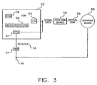
- FIG. 3 A high level block diagram of the major components of the temperature control circuitry is illustrated in Fig. 3.
- Rotating circuit board 48 rotates with drum 10 to communicate heater control information to drum 10 and to communicate temperature information to software located on system controller board 52 (stationary).
- Communications board 50 (stationary) converts serial data from system controller board 52 to optical data rotating board 48, and vice versa.
- Machine interface board 54 supplies an ACCLOCK signal 56 which is used to synchronize serial communications between system controller board 52 and rotating board 48.
- System controller board 52 provides memory 58 in which the temperature control software resides.
- Microprocessor 60, time processing unit 62 and I/O unit 64 are used by the software to monitor and regulate the temperature of exterior surface 14 of drum 10.
- system controller board 52 loads heater control data indicating which electrical resistance heaters 36, 38 and 40 to turn on or off into I/O unit 64 to be shifted serially to communication boards 50.
- Communications board 50 converts the data to an optical signal which is sent to rotating board 48 over optical link 66.
- Rotating board 66 interprets this data into signals which are used to switch power on or off independently to electrical resistance heaters 36, 38 and 40.
- rotating board 48 reads data from temperature sensors 42, 44 and 46 and sends this data via optical link 66 to communications board 50.
- Communications board 50 sends this data to system controller board 52.
- temperature data is read by time processing unit 62. Software can then read this data and convert the temperature data into temperatures and react accordingly to turn electrical resistance heater 36, 38 and 40 on or off.
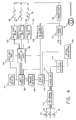
- Fig. 4 illustrates a block diagram of rotating board 48 attached to rotating drum 10.
- Optical transmitter 92 is mounted on the rotational axis of drum 10 facing communications board 50.
- Optical detector 94 an infrared photosensor, is mounted next to optical transmitter 92 as close as possible to optical transmitter 92 and facing communications board 50. All optical transmitters and sensors face each other across the space between communications board 50 and rotating board 48 at a distance of 0.6 inches (1.5 centimeters).
- Control signals for electrical resistance heaters 36, 38 and 40 are received via optical link 66 by optical detector 94.
- the control information is passed to shift register 96 through heater control bit latch 98 to solid state relay 100 for electrical resistance heater 36, to solid state relay 102 for electrical resistance heater 38 and to solid state relay 104 for electrical resistance heater 40.
- Watchdog timer 106 watches an interruption in the receipt of the serial data from optical link 66.
- Received data is also passed from shift register 96 through framing detector 108 received serial data for validity and performs control functions.
- Temperature data is received from temperature sensors 42, 44 and 46 by RTD signal conditioner 112 and passed to an analog multiplexer 114 under control from state machine 110.
- state machine 110 then transmits temperature data through V to F converter 116 to optical transmitter 92 for transmission across optical link 66 to communications board 50.
- AC power is received by electrical resistance heaters 36, 38 and 40 through slip rings 67.
- Transformer 118, power supply 120 and AC clock generator 122 (HI 111) provide overhead functions.
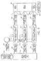
- photothermographic processor drum 200 has electrical resistance Zone 1 heater 202, Zone 2 electrical resistance heater 204 and Zone 3 electrical resistance heater 206.
- AC power from power slip rings 208 is supplied over bus 210 to Zone 1 solid state relay with zero crossing triggering circuit 212, to Zone 2 solid state relay with zero crossing triggering circuit 214 and to Zone 3 solid state relay with zero crossing triggering circuit 216.
- Circuits 212, 214 and 216 supply switched AC power respectively to heaters 202, 204 and 206 over respective power links 218, 220 and 222.
- Circuits 212, 214 and 216 receive heater control signals from signal decode and heater control bit latch 224 over control links 226, 228 and 230.
- Latch 224 receives optically coupled control signals from the system control board (arrow 132).
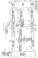
- Fig. 7 is a schematic diagram of relevant components of the Zone 2 heater system.
- Latch 224 is a MC74HC173, whose pin 4 supplies the heater control signal over control link 228.
- Circuit 114 includes zero crossing optocoupler 240 (ISO2 type MOC 3033) and triac 242.
- the control link 228 from latch 224 pin 4 turns on optocoupler 240 which turns on triac 242 (and thus Zone 2 heater 204 (Fig. 5)) at the next AC line voltage zero crossing and maintains triac 242 in the on state until control link 228 goes low. At this time, the triac 242 will turn off the Zone 2 heater 204 current at the next AC line zero crossing.
- the system of Figs. 6 and 8 obviates the limitations of the Figs. 5 and 7 system.
- the Zone 2 heater control signal on link 228 from latch 224 is supplied to a microprocessor 250 which delays the heater control signal over link 252.
- the Zone 2 solid state relay circuit 254 operates with random turn-on triggering.
- Fig. 8 shows microprocessor 250 to be PIC12C508 and circuit 254 to include ISO2 optocoupler 256 and triac 242.
- the triac 242 can be turned on at any time (random turn-on). This allows us to turn on the triac 242 with a narrow pulse and the triac will then stay on until the next zero crossing of the AC line.
- the program in the PIC microprocessor 250 operates by having two inputs. One is a square wave generated from the AC line and has it's transitions synchronized to the AC line zero crossings.
- the other input is the digital control line from latch 224 pin 4.
- a pulse is generated to the triac 242 after a variable delay time measured from the next AC line zero crossing. This delay time decreases in a linear manner until the delay time goes to zero at which time the triac trigger pulse occurs immediately after the AC line zero crossing. This effectively allows the triac 242 to conduct for the full line cycle and applies maximum power to the heater 204.
- the microprocessor 250 increases the delay time in a linear manner until the point is reached where the delay time is greater than the time for 1 ⁇ 2 AC cycle. When this happens, the delay time is restarted and no trigger pulse is generated. This effectively applies no power to the heater 204.
- the heater 204 is supplied with a varying, phase controlled duty cycle which effectively ramps the heater 204 power up and down in response to the binary control signal. This softens the turn-on and turn-off of the heater 204 and spreads the charge in line current over a longer time, which allows the unit to pass the new European flicker requirements. Moreover, the large expense of hardware and software design and re-qualification of a new design is mitigated, production is not impacted and resources for new product designs are available.
- Zone 2 heater 204 could also be used to control the temperature of Zone 1 heater 202 and/or Zone 3 heater 206.
Landscapes
- Physics & Mathematics (AREA)
- General Physics & Mathematics (AREA)
- Photographic Developing Apparatuses (AREA)
- Control Of Resistance Heating (AREA)
- Control Of Temperature (AREA)
- Control Of Electrical Variables (AREA)
Abstract
Description
- Fig. 1 is a perspective view of a portion of a thermal processor utilizing a rotatable, electrically heated drum.
- Fig. 2 is a cross-sectional view of the drum shown in Fig. 1.
- Fig. 3 is a high level block diagram of an electronic temperature control system incorporating the present invention.
- Fig. 4 is a block diagram of a rotating board shown in Fig. 3.
- Fig. 5 is a diagrammatic view illustrating the known heater control system.
- Fig. 6 is a diagrammatic view illustrating the heater control system of the present invention.
- Fig. 7 is a schematic diagram of the system of Fig. 5.
- Fig. 8 is schematic diagram of the system of Fig. 6.
Claims (6)
- A control system for reducing flicker in an electrical resistance heater comprising:a source of AC (alternating current) current for supplying AC current to an electrical resistance heater;a bidirectional solid state switching device connected between said source and said electrical resistance heater; anda control circuit for controlling said bidirectional solid state switching device to supply a varying, phase controlled duty cycle of current to said heater which effectively ramps heater power up and down in response to a binary control signal which randomly turns on said switching device.
- The control system of claim 1 wherein said bidirectional solid state switching device is a solid state triac.
- The control system of claim 2 wherein said control circuit includes a random turn-on optocoupler for randomly turning on said triac and a microprocessor linked to said optocoupler for controlling said optocoupler.
- The control system of claim 3 wherein in response to a square wave input having its transitions synchronized to said AC line zero crossing and a control input that is high, a pulse is generated to said triac after a variable delay time measured from the next AC line crossing.
- The control system of claim 1 wherein said AC current is supplied to an electrical resistance heater located on a member for heat processing exposed photographic media.
- The control system of claim 5 wherein said member is a rotating drum which is heated by said resistance heater and which contacts exposed photothermographic media for heat processing.
Applications Claiming Priority (2)
| Application Number | Priority Date | Filing Date | Title |
|---|---|---|---|
| US742977 | 2000-12-20 | ||
| US09/742,977 US6420685B1 (en) | 2000-12-20 | 2000-12-20 | Control of electrical heater to reduce flicker |
Publications (2)
| Publication Number | Publication Date |
|---|---|
| EP1223480A2 true EP1223480A2 (en) | 2002-07-17 |
| EP1223480A3 EP1223480A3 (en) | 2004-08-18 |
Family
ID=24987013
Family Applications (1)
| Application Number | Title | Priority Date | Filing Date |
|---|---|---|---|
| EP01204828A Withdrawn EP1223480A3 (en) | 2000-12-20 | 2001-12-10 | Control of electrical heater to reduce flicker |
Country Status (3)
| Country | Link |
|---|---|
| US (1) | US6420685B1 (en) |
| EP (1) | EP1223480A3 (en) |
| JP (1) | JP2002214754A (en) |
Families Citing this family (5)
| Publication number | Priority date | Publication date | Assignee | Title |
|---|---|---|---|---|
| US6849833B2 (en) * | 2003-02-13 | 2005-02-01 | Eastman Kodak Company | Logical flicker suppression for a temperature controlled heater load |
| US6901226B2 (en) * | 2003-05-19 | 2005-05-31 | Xerox Corporation | Power control for a xerographic fusing apparatus |
| US7161819B2 (en) * | 2004-07-22 | 2007-01-09 | Valeo Electrical Systems, Inc. | Zero-crossing correction in sinusoidally commutated motors |
| JP4899654B2 (en) * | 2006-06-15 | 2012-03-21 | コニカミノルタビジネステクノロジーズ株式会社 | Lamp control device |
| CA2689104A1 (en) * | 2008-12-22 | 2010-06-22 | Thermolec Ltee | Pulse modulation heating system and method |
Family Cites Families (8)
| Publication number | Priority date | Publication date | Assignee | Title |
|---|---|---|---|---|
| JPS5978495A (en) * | 1982-10-27 | 1984-05-07 | オリンパス光学工業株式会社 | Lamp firing circuit |
| US4580088A (en) * | 1984-02-29 | 1986-04-01 | General Electric Company | Soft-starting phase-control circuit for low voltage load |
| US5580478A (en) * | 1994-05-09 | 1996-12-03 | Minnesota Mining And Manufacturing Company | Apparatus for controlling the temperature of and a moveable, electrically heated object using two way on axis optical communication |
| JPH10115997A (en) * | 1996-10-09 | 1998-05-06 | Canon Inc | Power control device |
| JPH10133504A (en) * | 1996-10-25 | 1998-05-22 | Sharp Corp | Lamp lighting control device in image forming apparatus |
| NL1006388C2 (en) * | 1997-06-25 | 1998-12-29 | Oce Tech Bv | Device for controlling the power supply to a load in a reproduction device, in particular to a fixing unit. |
| US6097006A (en) * | 1997-09-24 | 2000-08-01 | Brother Kogyo Kabushiki Kaisha | Fixing unit for use in image forming device |
| US6111230A (en) * | 1999-05-19 | 2000-08-29 | Lexmark International, Inc. | Method and apparatus for supplying AC power while meeting the European flicker and harmonic requirements |
-
2000
- 2000-12-20 US US09/742,977 patent/US6420685B1/en not_active Expired - Fee Related
-
2001
- 2001-11-19 JP JP2001353167A patent/JP2002214754A/en active Pending
- 2001-12-10 EP EP01204828A patent/EP1223480A3/en not_active Withdrawn
Also Published As
| Publication number | Publication date |
|---|---|
| JP2002214754A (en) | 2002-07-31 |
| EP1223480A3 (en) | 2004-08-18 |
| US6420685B1 (en) | 2002-07-16 |
| US20020074325A1 (en) | 2002-06-20 |
Similar Documents
| Publication | Publication Date | Title |
|---|---|---|
| US6420685B1 (en) | Control of electrical heater to reduce flicker | |
| CA1053741A (en) | Contact heat fixing apparatus for electrophotographic reproduction machines | |
| US5580478A (en) | Apparatus for controlling the temperature of and a moveable, electrically heated object using two way on axis optical communication | |
| JP2001100588A (en) | Heating device and image forming device | |
| US6849833B2 (en) | Logical flicker suppression for a temperature controlled heater load | |
| JP2001242743A (en) | Method of correcting non-contact temperature sensor for detecting temperature of fixing device and method of controlling temperature of fixing device | |
| US6744014B1 (en) | Apparatus for controlling temperature of moveable electrically heated objects/drums | |
| JPH10213996A (en) | Power controller for thermal fixing device | |
| JP2943120B2 (en) | Temperature control method for roller-type thermal fuser | |
| EP1282009A2 (en) | Segmented heated drum processor | |
| JP3186906B2 (en) | Fixing device | |
| JPS63184776A (en) | Fixing temperature control device | |
| JPH112988A (en) | Fixing temperature control method | |
| JP3477051B2 (en) | Heat fixing device | |
| JP2003215974A (en) | Fixing device and image forming apparatus provided with the same | |
| JPH0664407B2 (en) | Fixing device | |
| JPH04371985A (en) | Temperature control over fixing unit of electrophotographic printer | |
| JPH0210427B2 (en) | ||
| JPH0619363A (en) | Fixing device | |
| KR100189759B1 (en) | Method to keep uniform fixing quality high | |
| JPH10333488A (en) | Method for controlling fixing temperature | |
| JPH03132781A (en) | developing device | |
| JPH112992A (en) | Fixing temperature control method | |
| JPH05188807A (en) | Fixing device | |
| JPS63280280A (en) | Fixing temperature control device |
Legal Events
| Date | Code | Title | Description |
|---|---|---|---|
| PUAI | Public reference made under article 153(3) epc to a published international application that has entered the european phase |
Free format text: ORIGINAL CODE: 0009012 |
|
| AK | Designated contracting states |
Kind code of ref document: A2 Designated state(s): AT BE CH CY DE DK ES FI FR GB GR IE IT LI LU MC NL PT SE TR |
|
| AX | Request for extension of the european patent |
Free format text: AL;LT;LV;MK;RO;SI |
|
| PUAL | Search report despatched |
Free format text: ORIGINAL CODE: 0009013 |
|
| AK | Designated contracting states |
Kind code of ref document: A3 Designated state(s): AT BE CH CY DE DK ES FI FR GB GR IE IT LI LU MC NL PT SE TR |
|
| AX | Request for extension of the european patent |
Extension state: AL LT LV MK RO SI |
|
| 17P | Request for examination filed |
Effective date: 20050117 |
|
| AKX | Designation fees paid |
Designated state(s): DE FR GB |
|
| RBV | Designated contracting states (corrected) |
Designated state(s): DE FR GB |
|
| STAA | Information on the status of an ep patent application or granted ep patent |
Free format text: STATUS: THE APPLICATION IS DEEMED TO BE WITHDRAWN |
|
| 18D | Application deemed to be withdrawn |
Effective date: 20060504 |