EP1224978A2 - Broyeur pour le broyage de bois de récuperation et d'autres produits - Google Patents
Broyeur pour le broyage de bois de récuperation et d'autres produits Download PDFInfo
- Publication number
- EP1224978A2 EP1224978A2 EP02380002A EP02380002A EP1224978A2 EP 1224978 A2 EP1224978 A2 EP 1224978A2 EP 02380002 A EP02380002 A EP 02380002A EP 02380002 A EP02380002 A EP 02380002A EP 1224978 A2 EP1224978 A2 EP 1224978A2
- Authority
- EP
- European Patent Office
- Prior art keywords
- machine
- rollers
- shredding
- motors
- roller
- Prior art date
- Legal status (The legal status is an assumption and is not a legal conclusion. Google has not performed a legal analysis and makes no representation as to the accuracy of the status listed.)
- Withdrawn
Links
- 239000002023 wood Substances 0.000 title claims abstract description 13
- 238000005520 cutting process Methods 0.000 claims abstract description 24
- 239000000463 material Substances 0.000 claims abstract description 15
- 238000007689 inspection Methods 0.000 claims abstract description 7
- 230000009467 reduction Effects 0.000 claims description 9
- 230000009471 action Effects 0.000 claims description 4
- 230000007246 mechanism Effects 0.000 claims description 4
- 238000004140 cleaning Methods 0.000 claims description 3
- 238000012423 maintenance Methods 0.000 claims description 2
- 238000004519 manufacturing process Methods 0.000 abstract description 4
- 239000002184 metal Substances 0.000 abstract description 2
- 229910052751 metal Inorganic materials 0.000 abstract description 2
- 230000037431 insertion Effects 0.000 abstract 1
- 238000003780 insertion Methods 0.000 abstract 1
- 239000002994 raw material Substances 0.000 description 3
- 239000007787 solid Substances 0.000 description 3
- XEEYBQQBJWHFJM-UHFFFAOYSA-N Iron Chemical compound [Fe] XEEYBQQBJWHFJM-UHFFFAOYSA-N 0.000 description 2
- 239000011093 chipboard Substances 0.000 description 2
- 239000002699 waste material Substances 0.000 description 2
- 230000002411 adverse Effects 0.000 description 1
- 238000006073 displacement reaction Methods 0.000 description 1
- 238000009826 distribution Methods 0.000 description 1
- 229910052742 iron Inorganic materials 0.000 description 1
- 239000002923 metal particle Substances 0.000 description 1
- 230000003287 optical effect Effects 0.000 description 1
- 230000008439 repair process Effects 0.000 description 1
- 238000003466 welding Methods 0.000 description 1
Images


Classifications
-
- B—PERFORMING OPERATIONS; TRANSPORTING
- B02—CRUSHING, PULVERISING, OR DISINTEGRATING; PREPARATORY TREATMENT OF GRAIN FOR MILLING
- B02C—CRUSHING, PULVERISING, OR DISINTEGRATING IN GENERAL; MILLING GRAIN
- B02C18/00—Disintegrating by knives or other cutting or tearing members which chop material into fragments
- B02C18/06—Disintegrating by knives or other cutting or tearing members which chop material into fragments with rotating knives
- B02C18/16—Details
-
- B—PERFORMING OPERATIONS; TRANSPORTING
- B02—CRUSHING, PULVERISING, OR DISINTEGRATING; PREPARATORY TREATMENT OF GRAIN FOR MILLING
- B02C—CRUSHING, PULVERISING, OR DISINTEGRATING IN GENERAL; MILLING GRAIN
- B02C18/00—Disintegrating by knives or other cutting or tearing members which chop material into fragments
- B02C18/06—Disintegrating by knives or other cutting or tearing members which chop material into fragments with rotating knives
- B02C18/14—Disintegrating by knives or other cutting or tearing members which chop material into fragments with rotating knives within horizontal containers
-
- B—PERFORMING OPERATIONS; TRANSPORTING
- B02—CRUSHING, PULVERISING, OR DISINTEGRATING; PREPARATORY TREATMENT OF GRAIN FOR MILLING
- B02C—CRUSHING, PULVERISING, OR DISINTEGRATING IN GENERAL; MILLING GRAIN
- B02C18/00—Disintegrating by knives or other cutting or tearing members which chop material into fragments
- B02C18/06—Disintegrating by knives or other cutting or tearing members which chop material into fragments with rotating knives
- B02C18/16—Details
- B02C18/18—Knives; Mountings thereof
- B02C2018/188—Stationary counter-knives; Mountings thereof
Definitions
- the technical field involved in this invention is that of manufacturing machinery for processing wood, and in particular that of machinery for shredding wood for obtaining chips or shreds for industrial reuse.
- chipboard as this has been done for many years now initially arose as a way to make use of the remains of low quality wood which could not be used in conventional furniture, which had always been made of solid wood.
- chipboard involves two very important advantages as compared with using solid wood.
- the first consists in making use of the remains of low quality wood or woods, and the second its low price in respect of solid woods.
- This invention covers a grinding machine with great production advantages as compared with prior items, balancing the consumption flow of raw material placed in the hopper and also preventing damage through snagging, apart from facilitating the removal of any possible unwanted material.
- This invention also allows automatic stoppage when there is any snagging, preventing the drive motors from continuing to run until there is a manual stop.
- the machine covered by this invention is also designed for removing the shredded products by means of a conveyor belt, as well as removing any unwanted metal particles by means of an electro-magnet.
- This machine has a pair of rollers turning in opposite directions which act on a central part, so that the cutting capacity is duplicated in an essentially identical space as compared with any of the twin-roller antecedents.
- the central part is able to move downwards when the roller motion, along with the product that the machine is attempting to grind, exerts a force greater than the cutting resistance programmed for the material to be ground.
- the tare setting of said central part would mean that this would move downwards, against the action of a spring or a pneumatic or hydraulic device, and in its displacement it would act on a mechanical, optical or other form of detector which cuts off the current for driving the motors, and where applicable all the auxiliary mechanisms that might be necessary to guarantee the safety of the operator removing the unwanted item.
- the body of the machine has opening windows at both sides, as inspection panels for cleaning and removing any unwanted products as described above. Opening either of these inspection covers will obviously require/and or give rise to cutting off the current needed, to make it impossible for the machine to run in these conditions.
- the motors have reduction units to adjust the speed of the rollers to the optimum running specifications.
- the motor power and/or the turning speed are expected to be specifically prepared for the form of usage, as well as the material to be shredded or the conditions of the raw material. If the raw material is, for example, very fine wood, very high roller turning speeds can be used, whilst if the material to be crushed is plastic the heat produced by friction would also have to be taken into account to prevent an excessively high rotation speed from adversely affecting the cutting conditions or the resulting shredded material.
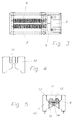
- FIG. 1 represents the base of the machine on which the other items are held and in particular the shredding box 2 and a table 3 for supporting the motors 4.
- 5 indicates a reception hopper for the material to be shredded and 6 opening inspection covers in the shredding box 2 at the bottom of the sides.
- the motors 4 are provided with a cover 7 (individual or joint) fitted with the required safety means so that this part of the machine cannot be operating while the inspection panels are open.
- rollers 8 turn by means of the motors 4 through a reduction unit 9 fitted between these, the speed and power of the motors 4 as well as the reduction ratio of the reduction unit 9 being adjusted to suit the particular needs.
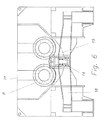
- the shredding box On two of its sides the shredding box has two opposite parts 10 which have "U" shaped cutaways which house the shredding rollers 8 and in which these are fitted, by means of securing plates 12.
- the shredding box has a second internal hopper 13, converging downwards, fitted so that the exterior sides do not allow any part through, which is assisted by the turning motion of the roller which in this zone is upward (in normal operation conditions).
- the rollers 8 move in opposite directions, and act on a central part 14, thus providing two cutting zones, as opposed to the single zone found in known antecedents.
- a support base provided with elastic retraction means for withdrawal when a force greater than the usual level is applied to these, which might happen when the roller or the rollers attempt to crush extremely thick metal parts.
- This central part 14 also has lateral stops 15 which prevent the material to be shredded from extending beyond the cutting zone, which would cause a particular flow of uncrushed material to parts of the machine where this should not reach, possibly damaging sensitive parts of the machine in any case.
- the central part is held in a preferably "H" shaped structure by a base 18 with the relevant housing 19, fitted with side supports 16 set on support legs 17, in such a way that these supports 16 do not prevent or hinder the shredded material from falling through.
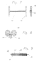
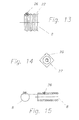
- rollers are held at their ends 20 and 21 in the corresponding cutaways 11 made in the side parts 10 of the box 2 and provided with a slotted profile 22 on which a further spiral slot 23 is made.
- the roller is connected to the motor through a reduction gearbox 9 by means of two connection flanges 24 and 25.
- the cutting tools 26 are located on the roller surface, in any suitable arrangement, according to the profile of the central part against which this acts. It is thus possible for each turn of the roller to make one or more cuts in the material to be shredded (each ring has one or more cutting tools) and as a particular embodiment it being designed for the arrangement to be spiral in one or more lines per ring. Securing can be by means of welding, screwing or any other suitable securing means.
- the set of grinding rollers 8 prevents any particular unshredded materials from remaining there, the collection thus being fully effective.
Landscapes
- Engineering & Computer Science (AREA)
- Food Science & Technology (AREA)
- Crushing And Pulverization Processes (AREA)
- Debarking, Splitting, And Disintegration Of Timber (AREA)
- Dry Formation Of Fiberboard And The Like (AREA)
- Disintegrating Or Milling (AREA)
Applications Claiming Priority (2)
| Application Number | Priority Date | Filing Date | Title |
|---|---|---|---|
| ES200100062 | 2001-01-05 | ||
| ES200100062U ES1048083Y (es) | 2001-01-05 | 2001-01-05 | Bielas avanzadas de empuje tangencial |
Publications (2)
| Publication Number | Publication Date |
|---|---|
| EP1224978A2 true EP1224978A2 (fr) | 2002-07-24 |
| EP1224978A3 EP1224978A3 (fr) | 2004-11-24 |
Family
ID=8496374
Family Applications (1)
| Application Number | Title | Priority Date | Filing Date |
|---|---|---|---|
| EP02380002A Withdrawn EP1224978A3 (fr) | 2001-01-05 | 2002-01-04 | Broyeur pour le broyage de bois de récuperation et d'autres produits |
Country Status (2)
| Country | Link |
|---|---|
| EP (1) | EP1224978A3 (fr) |
| ES (1) | ES1048083Y (fr) |
Cited By (4)
| Publication number | Priority date | Publication date | Assignee | Title |
|---|---|---|---|---|
| WO2009027022A1 (fr) * | 2007-08-24 | 2009-03-05 | Amni Maschinenbau Gmbh | Broyeuse à rotors |
| EP2394742A1 (fr) * | 2010-06-08 | 2011-12-14 | AMNI Maschinenbau GmbH | Broyeur |
| CN107311262A (zh) * | 2017-08-23 | 2017-11-03 | 王晓炜 | 一种工业污水处理装置 |
| CN116078533A (zh) * | 2022-12-12 | 2023-05-09 | 博远机电(南通)有限公司 | 一种防飞溅的工业切碎机 |
Citations (5)
| Publication number | Priority date | Publication date | Assignee | Title |
|---|---|---|---|---|
| ES1000270U (es) | 1986-07-23 | 1988-03-01 | Tomas De Bera Francisco | Trituradora de madera |
| EP0419919A1 (fr) | 1989-09-28 | 1991-04-03 | VECOPLAN GmbH MASCHINENFABRIK | Appareil de réduction des déchets |
| EP0529221A1 (fr) | 1991-08-23 | 1993-03-03 | Norbert Hammel | Dispositif de broyage |
| EP0876843A1 (fr) | 1997-05-10 | 1998-11-11 | HAMMEL Recyclingtechnik GmbH | Dispositif de broyage de matière |
| ES1045137U (es) | 1999-02-05 | 2000-07-16 | Optibag Systems Ab | Trituradora con descarte automatico de productos irreducibles |
Family Cites Families (6)
| Publication number | Priority date | Publication date | Assignee | Title |
|---|---|---|---|---|
| US1509005A (en) * | 1922-02-07 | 1924-09-16 | Francis J Straub | Crushing rolls |
| US2479523A (en) * | 1946-04-04 | 1949-08-16 | Francis J Straub | Crusher for cinders and the like |
| US3419223A (en) * | 1966-12-23 | 1968-12-31 | Nelson H. Morin | Granulators |
| US5484112A (en) * | 1993-06-01 | 1996-01-16 | Koenig; Larry E. | Modular shear shredder |
| DE19619411A1 (de) * | 1996-05-14 | 1997-11-20 | Werner Zink | Kompakte Aufbereitungsmaschine für Mineralstoffe |
| DE19819989A1 (de) * | 1998-05-05 | 1999-11-11 | Franz Stark | Vorrichtung zum Zerkleinern von Gegenständen |
-
2001
- 2001-01-05 ES ES200100062U patent/ES1048083Y/es not_active Expired - Fee Related
-
2002
- 2002-01-04 EP EP02380002A patent/EP1224978A3/fr not_active Withdrawn
Patent Citations (5)
| Publication number | Priority date | Publication date | Assignee | Title |
|---|---|---|---|---|
| ES1000270U (es) | 1986-07-23 | 1988-03-01 | Tomas De Bera Francisco | Trituradora de madera |
| EP0419919A1 (fr) | 1989-09-28 | 1991-04-03 | VECOPLAN GmbH MASCHINENFABRIK | Appareil de réduction des déchets |
| EP0529221A1 (fr) | 1991-08-23 | 1993-03-03 | Norbert Hammel | Dispositif de broyage |
| EP0876843A1 (fr) | 1997-05-10 | 1998-11-11 | HAMMEL Recyclingtechnik GmbH | Dispositif de broyage de matière |
| ES1045137U (es) | 1999-02-05 | 2000-07-16 | Optibag Systems Ab | Trituradora con descarte automatico de productos irreducibles |
Cited By (6)
| Publication number | Priority date | Publication date | Assignee | Title |
|---|---|---|---|---|
| WO2009027022A1 (fr) * | 2007-08-24 | 2009-03-05 | Amni Maschinenbau Gmbh | Broyeuse à rotors |
| EP2394742A1 (fr) * | 2010-06-08 | 2011-12-14 | AMNI Maschinenbau GmbH | Broyeur |
| CN107311262A (zh) * | 2017-08-23 | 2017-11-03 | 王晓炜 | 一种工业污水处理装置 |
| CN107311262B (zh) * | 2017-08-23 | 2018-04-24 | 青海天择生态环境治理有限公司 | 一种工业污水处理装置 |
| CN116078533A (zh) * | 2022-12-12 | 2023-05-09 | 博远机电(南通)有限公司 | 一种防飞溅的工业切碎机 |
| CN116078533B (zh) * | 2022-12-12 | 2023-12-22 | 博远机电(南通)有限公司 | 一种防飞溅的工业切碎机 |
Also Published As
| Publication number | Publication date |
|---|---|
| EP1224978A3 (fr) | 2004-11-24 |
| ES1048083Y (es) | 2001-11-01 |
| ES1048083U (es) | 2001-06-16 |
Similar Documents
| Publication | Publication Date | Title |
|---|---|---|
| KR101753105B1 (ko) | 재활용 폐기물 분쇄장치 | |
| US5402948A (en) | Comminuting device with face | |
| JP6114756B2 (ja) | 切断−粉砕ミル | |
| CN202447134U (zh) | 一种中草药粉碎机 | |
| CN114130499B (zh) | 一种多级粉碎高效节能磨粉机 | |
| EP1224978A2 (fr) | Broyeur pour le broyage de bois de récuperation et d'autres produits | |
| CN201179456Y (zh) | 自动排杂物环式破碎机 | |
| CN206082741U (zh) | 一种硬盘粉碎机 | |
| US3489078A (en) | Shredding type hammermill with automobile-flattening feeder | |
| KR200405320Y1 (ko) | 폐비닐 분쇄기 | |
| CN105562143A (zh) | 一种圆辊粉碎机 | |
| KR100200949B1 (ko) | 곡물 및 고추 분쇄기와 그 분쇄방법 | |
| CN2712464Y (zh) | 离合式多用粉碎机 | |
| JPH048998Y2 (fr) | ||
| CN215541340U (zh) | 超细微粉碎机 | |
| CN212943193U (zh) | 一种生物质原料粉碎机 | |
| CN221208223U (zh) | 一种递进式粉碎装置 | |
| CN216727508U (zh) | 一种便于更换锤片的锤片粉碎机 | |
| CN106345586A (zh) | 一种硬盘粉碎机 | |
| CN220879028U (zh) | 一种耐火性混凝土砌块生产用粉碎机 | |
| CN219377418U (zh) | 一种干式多级粉磨机 | |
| CN222984558U (zh) | 一种便于进料的食品粉碎机 | |
| CN219377283U (zh) | 一种鹿筋超微粉碎装置 | |
| CN211274930U (zh) | 一种可以自动排出料头的双轴金属切屑粉碎机 | |
| CN222789352U (zh) | 一种熔炼用圆盘粉碎机 |
Legal Events
| Date | Code | Title | Description |
|---|---|---|---|
| PUAI | Public reference made under article 153(3) epc to a published international application that has entered the european phase |
Free format text: ORIGINAL CODE: 0009012 |
|
| AK | Designated contracting states |
Kind code of ref document: A2 Designated state(s): AT BE CH CY DE DK ES FI FR GB GR IE IT LI LU MC NL PT SE TR |
|
| AX | Request for extension of the european patent |
Free format text: AL;LT;LV;MK;RO;SI |
|
| RIN1 | Information on inventor provided before grant (corrected) |
Inventor name: SABATER BELENGUER, ISIDRO |
|
| 17P | Request for examination filed |
Effective date: 20021212 |
|
| PUAL | Search report despatched |
Free format text: ORIGINAL CODE: 0009013 |
|
| AK | Designated contracting states |
Kind code of ref document: A3 Designated state(s): AT BE CH CY DE DK ES FI FR GB GR IE IT LI LU MC NL PT SE TR |
|
| AX | Request for extension of the european patent |
Extension state: AL LT LV MK RO SI |
|
| RIC1 | Information provided on ipc code assigned before grant |
Ipc: 7B 02C 18/14 A |
|
| AKX | Designation fees paid |
Designated state(s): AT BE CH CY DE DK ES FI FR GB GR IE IT LI LU MC NL PT SE TR |
|
| STAA | Information on the status of an ep patent application or granted ep patent |
Free format text: STATUS: THE APPLICATION IS DEEMED TO BE WITHDRAWN |
|
| 18D | Application deemed to be withdrawn |
Effective date: 20090203 |