EP1224982A2 - Vorrichtung zum Auftragen von Farbe auf Flächen - Google Patents
Vorrichtung zum Auftragen von Farbe auf Flächen Download PDFInfo
- Publication number
- EP1224982A2 EP1224982A2 EP02000441A EP02000441A EP1224982A2 EP 1224982 A2 EP1224982 A2 EP 1224982A2 EP 02000441 A EP02000441 A EP 02000441A EP 02000441 A EP02000441 A EP 02000441A EP 1224982 A2 EP1224982 A2 EP 1224982A2
- Authority
- EP
- European Patent Office
- Prior art keywords
- handle
- stem
- drip tray
- pipe socket
- tray
- Prior art date
- Legal status (The legal status is an assumption and is not a legal conclusion. Google has not performed a legal analysis and makes no representation as to the accuracy of the status listed.)
- Granted
Links
- 239000003973 paint Substances 0.000 title claims abstract description 7
- 239000011248 coating agent Substances 0.000 title 1
- 238000000576 coating method Methods 0.000 title 1
- 230000002093 peripheral effect Effects 0.000 description 3
- 238000010276 construction Methods 0.000 description 2
- 238000001746 injection moulding Methods 0.000 description 2
- 239000000463 material Substances 0.000 description 2
- 208000027418 Wounds and injury Diseases 0.000 description 1
- 238000011109 contamination Methods 0.000 description 1
- 230000006378 damage Effects 0.000 description 1
- 238000006073 displacement reaction Methods 0.000 description 1
- 238000001035 drying Methods 0.000 description 1
- 230000000694 effects Effects 0.000 description 1
- 239000000834 fixative Substances 0.000 description 1
- 235000021478 household food Nutrition 0.000 description 1
- 208000014674 injury Diseases 0.000 description 1
- 238000003754 machining Methods 0.000 description 1
- 238000000034 method Methods 0.000 description 1
- 239000004753 textile Substances 0.000 description 1
Images


Classifications
-
- B—PERFORMING OPERATIONS; TRANSPORTING
- B05—SPRAYING OR ATOMISING IN GENERAL; APPLYING FLUENT MATERIALS TO SURFACES, IN GENERAL
- B05C—APPARATUS FOR APPLYING FLUENT MATERIALS TO SURFACES, IN GENERAL
- B05C17/00—Hand tools or apparatus using hand held tools, for applying liquids or other fluent materials to, for spreading applied liquids or other fluent materials on, or for partially removing applied liquids or other fluent materials from, surfaces
- B05C17/02—Rollers ; Hand tools comprising coating rollers or coating endless belts
- B05C17/0222—Rollers ; Hand tools comprising coating rollers or coating endless belts comprising protecting shields, drip pans, spatter guards or the like
Definitions
- the invention relates to a device for applying paint Surfaces, especially ceilings and / or walls, with a Applicator roller that rotates on a bracket attached to a handle is stored, and displaceable with one of the applicator roller on the stem drip tray, one from the stem penetrated opening and a protruding, the stem comprehensive, shorter than the stem trained pipe socket and the one of the stick-side peripheral region of the applicator roller comprehensive working position in a release position in which the Applicator roller is pushed out of the drip tray, is retractable and vice versa.
- a device of this type is known from DE 196 11 284 A1.
- the Return spring is within the stem designed as a tube arranged and on the one hand at the end of the handle remote from the application roller and on the other hand on a pipe socket encompassing the stem fastened, supported through a slot of the handle tab.
- a locking device can be blocked.
- the return spring assembly and the locking device lead to a comparatively complicated and elaborate structure without resulting in a greater advantage for the Handling results.
- There is also a risk that the Drip drip tray in the event of accidental triggering of the Snap mechanism snaps back into the working position in an uncontrolled manner.
- the known arrangement is therefore not easy and reasonable enough.
- the drip tray can be easily overcome Frictional force can be pushed into any desired position and lasts then frictionally in the respective position.
- the actuation or triggering a locking device is not necessary here.
- a Return spring and a locking device can be omitted.
- the Measures according to the invention therefore advantageously allow Way a highly simple and inexpensive construction as well as a high ease of use.
- the pipe socket can be useful in the area of its rear end provided with a conical narrowing and axially parallel slots his. In this way, there are resilient tabs on the stem, which can generate the desired frictional force. If one It should be desirable to increase the frictional force thus generated an annular spring surrounding the pipe socket in the slotted area be provided.
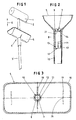
- the paint application device shown in FIG. 1 consists of a a jacket consisting of textile material Applicator roller 1, which in a manner known per se on a by a curved round rod etc. formed bracket 2 is rotatably mounted is attached to the front end of a rod-shaped stem 3, for example with a threaded piece in a stick-side Threaded sleeve is screwed in.
- the stem 3 makes a big one Radius of action. With the help of the handle 3 it is possible, for example, Ceilings or high room walls from the floor with a Paint application.
- the splash guard 4 contains a slidable on the handle 3 recorded drip tray 5, which according to double arrow 6 of one not shown here, the stem-side peripheral area the application roller 1 comprehensive working position in that of Figure 1 Basic release position in which the applicator roller 1 from the Drop tray 5 is pushed out, is retractable and vice versa. While applying paint to a surface the drip tray is in the stem side Circumferential area of the application roller 1 with sufficient play comprehensive Working position. For immersing the application roller 1 in a The droplet collecting tray 5 becomes a color supply in that of FIG. 1 Basic release position brought.
- the drip tray 5 In each position, the drip tray 5 is on the by friction Handle fixed in such a way that there is no automatic adjustment. Additional fixatives are not required. To adjust the Drip drip tray 5 becomes this while overcoming the frictional force shifted relative to the handle 3. The arrangement is to be made that the friction force can be overcome by manual operation.
- the drip tray 5 has, as shown in Figures 2 and 3, one opening on the bottom, penetrable by the handle 3 7. From the edge of the Opening 7 is formed on the drip tray 5 Pipe socket 8 downwards, through which the stem 3 also can be pushed through.
- the pipe socket 8 is only a few centimeters long and thus much shorter than the stem 3, so that it is sufficient Freedom of displacement results.
- an as Extension of the pipe socket 8 trained, in the interior of the Drop collecting bowl 1 protruding, the opening 7 encompassing Collar 9 is provided, which can stiffen the opening area.
- the collar 9 can be arranged in the longitudinal direction of the drip tray 5 cursing opposite, upward notches 21 be provided, in which when the drip tray 5 is pushed up the applicator roller 1 carrying bracket 2 with a handle 3 adjacent area can intervene, as for example from FIG. 4 can be seen. This makes it mutually rotatable between applicator roller 1 and drip tray 5 prevents what guarantees a particularly high level of reliability and security.
- the pipe socket 8 is in this Area of its rear end with a conically narrowed neck 10 Mistake.
- axially parallel slots 11 are provided, so that these limited spring tabs 12 result.
- the spring tabs 12 should not result in the desired frictional force, it can additionally comprehensive ring spring 13 may be provided. This can also be used subsequently, provided that the spring tabs 12 in the course of Should take time.
- the drip tray 5 does not serve as an ink reservoir, but only as a splash guard, is within the Drop collecting tray 5 only comparatively little color, so that no significant risk of color leakage across the gap between Handle 3 and pipe socket 8 there.
- the in the Interior of the drip tray 5 projecting collar 9 possibly color on the bottom can prevent it in the above Overflow gap.
- the federal government 9 accordingly acts as Retaining weir.
- Area of the opening 7, a scraper ring 14 may be arranged under Avoiding a passage gap on the stem 3 may be present. On such a scraper ring 14 can simultaneously the desired frictional force generate or reinforce.
- the pipe socket 8 formed in one piece with the drip tray 1 can be designed as a handle.
- the Pipe socket 8 a preferably designed as a shrink tube Slipped on throw 15, which is designed as a handle and at the same time can exert radial clamping forces through which the spring tabs 12 to Achieving the desired frictional force can be pressed against the handle 3, so that on the above-mentioned ring spring 13 u. U. be waived can.
- Throw 15 also creates danger areas of the slotted approach 10 and the like covered. The length of the Throw 15 is dimensioned so that it is easy to grasp with one hand.
- the drip tray 5 with molded pipe socket 8 Component can be useful as a plastic injection molding getting produced.
- the throw 15 is retrofitted. There a tight seat can be provided so that there is a Clamp bracket results.
- the cover 15 can also be glued etc. be attached.
- a detachably attachable Cover cap 22 may be assigned, if necessary, on the drip tray 5 is put on. This results in a closed housing with an interior 23 receiving the applicator roller 1, so that the Application roller 1 cannot dry out over a longer period of time. This saves having to wash out the applicator roller 1 each time work is interrupted.
- the cover cap 22 is useful, similar to that in the household Food storage containers used, by a plug or Snap lock on the drip tray 5 detachably fixable. In the example shown, this is with one facing outwards projecting, circumferential edge strip 24 provided.
- the cover cap 22 has a circumferential claw-shaped cross section Edge strip 25 into which the edge strip 24 of the drip tray 5 can be snapped into place.
- the drip tray 5 and / or the cover cap 22 from an elastic flexible material. Both parts, the type of sub and The upper part of a two-part housing can interact as Plastic injection moldings are made.
- the application roller 1 is in the position on which FIG. 4 is based the drip tray 5 retracted and thus by the intervention of the bracket 2 in one of the notches 21 protected against twisting, so that a contact with the inner wall of the housing receiving it omitted.
- FIGS. 1 and 3 clearly show, on their lower one Outside with stiffening ribs 16 running away from the pipe socket 8 Mistake.
- Cross ribs 17 may be provided in the interior of the drip tray 5 . These are each with a central, upwardly open notch aligned with the notches 21 of the collar 9 26 provided, in which the bracket 2 can engage in the working position.
- the top of the transverse ribs 17 can be the bottom of the Drop collecting tray 5 following or adapted course exhibit.
- the drip tray is in the area of its upper edge 5 provided with a peripheral edge strip 18.
- Figure 5 shows another useful accessory for Drip drip pan 5.
- the inner transverse ribs 17 has a rider 27 attached, which has a central notch 28 in the upper edge, into which the Applicator roller 1 carrying bracket 2 with its handle 3 aimed Area in the working position, i.e. on the application roller 1 employed drip tray 5, engages.
- the tab 27 forms one Stop that causes the applicator roller 1 in the working position protrudes further from the drip tray 5 than at Not using the rider 27, as from a comparison of that in FIG. 5 position of the application roller drawn in with a solid line 1 when using the tab 27 with the one in FIG broken line indicated position of the application roller 1 without Use of the tab 27 is clearly visible.
- the tab 27 has, like FIG. 5 in conjunction with FIG. 6 reveals one on the top of each assigned Cross rib 17 of the drip tray 5 can be brought to rest yoke 29, of which two legs flanking the associated transverse rib 17 30 stick down. These are through one of the notches 26 associated cross rib associated web 31 connected to each other. The edge of the leg 30 remote from the web can fit the inner contour of the Drop drip tray 5 have an adapted course, so that a reliable fit results.
- On the opposite side of the legs 30 Side is a centrally located, protruding from the web 29 Tab 32 provided with a central notch 33 at the upper edge is provided. The thickness of the tab 32 corresponds approximately to the thickness of the Cross ribs 17. The clear distance between the legs 30 is such that that when plugged onto the associated transverse rib 17 light clamping effect and thus result in a good hold.
Landscapes
- Engineering & Computer Science (AREA)
- Mechanical Engineering (AREA)
- Coating Apparatus (AREA)
- Details Or Accessories Of Spraying Plant Or Apparatus (AREA)
- Application Of Or Painting With Fluid Materials (AREA)
Abstract
Description
- Figur 1
- eine perspektivische Ansicht einer erfindungsgemäßen Auftragvorrichtung mit aus der Tropfenauffangschale herausgeschobener Auftragwalze,
- Figur 2
- einen Querschnitt durch die Tropfenauffangschale,
- Figur 3
- eine Draufsicht auf die Unterseite der Tropfenauffangschale,
- Figur 4
- einen Vertikalschnitt durch die erfindungsgemäße Anordnung mit durch einen Deckel verschlossener Tropfenauffangschale,
- Figur 5
- einen Querschnitt durch die Auftragvorrichtung mit einem in der Tropfenauffangwanne angeordneten, den Abstand zwischen dieser und der Auftragwalze vergrößernden Anschlagelement und
- Figur 6
- eine Seitanansicht des Anschlagelements.
Claims (11)
- Vorrichtung zum Auftragen von Farbe auf Flächen, insbesondere Decken und/oder Wände, mit einer Auftragwalze (1), die auf einem auf einen Stiel (3) aufgesetzten Bügel (2) drehbar gelagert ist, und mit einer der Auftragwalze (1) zugeordneten, verschiebbar auf dem Stiel aufgenommenen Tropfenauffangschale (5), die eine vom Stiel (3) durchgriffene Öffnung (7) und einen hiervon abstehenden, den Stiel (3) umfassenden, kürzer als der Stiel (3) ausgebildeten Rohrstutzen (8) aufweist und die von einer den stielseitigen Umfangsbereich der Auftragwalze (1) umfassenden Arbeitsstellung in eine Freigabestellung, in der die Auftragwalze (1) aus der Tropfenauffangschale (5) herausgeschoben ist, zurückziehbar ist und umgekehrt, dadurch gekennzeichnet, dass die Tropfenauffangschale (5) durch von Hand überwindbare Reibkraft selbsthaltend auf dem Stiel (3) aufgenommen ist.
- Vorrichtung nach Anspruch 1, dadurch gekennzeichnet, dass der Rohrstutzen (8), der vorzugsweise mit seinem Innenumfang zumindest auf einem Teil seiner Länge satt am Außenumfang des Steils (3) anliegt, mit einer vorzugsweise elastischen Verengung versehen ist.
- Vorrichtung nach einem der vorhergehenden Ansprüche, dadurch gekennzeichnet, dass der Rohrstutzen (8) im Bereich seines hinteren Endes mit einem konisch verengten Ansatz (10) versehen ist, der vorzugsweise mit achsparallelen Schlitzen (11) versehen und von einer Federeinrichtung umfasst ist.
- Vorrichtung nach einem der vorhergehenden Ansprüche, dadurch gekennzeichnet, dass im Bereich der vom Stiel (3) durchgriffenen Öffnung (7) ein am Stiel (3) anliegender Abstreifring (14) vorgesehen ist.
- Vorrichtung nach einem der vorhergehenden Ansprüche, dadurch gekennzeichnet, dass dem Rohrstutzen (8) eine Griffanordnung vorzugsweise inform eines auf dem Rohrstutzen (8) aufgenommenen, als Griff ausgebildeten, handbreiten Schrumpfschlauchs zugeordnet ist.
- Vorrichtung nach einem der vorhergehenden Ansprüche, dadurch gekennzeichnet, dass die Tropfenauffangschale (5), die vorzugsweise im unteren Bereich mit vom Rohrstutzen (8) weglaufenden, äußeren Versteifungsrippen (16) versehen ist, mit inneren Querrippen (17) versehen ist, die vorzugsweise am oberen Rand mit einer mittigen Kerbe (26) versehen sind, in welche der die Auftragwalze (1) tragende Bügel (2) mit einem dem Stiel (3) zustrebenden Bereich einfahrbar ist.
- Vorrichtung nach einem der vorhergehenden Ansprüche, dadurch gekennzeichnet, dass die Tropfenauffangschale (5), mit einem die Öffnung (7) umfassenden, in den Schaleninnenraum vorspringenden, als Verlängerung des Rohrstutzens (8) ausgebildeten Bund (9) versehen ist, der vorzugsweise mit in Walzenlängsrichtung einander gegenüberliegenden Kerben (21) versehen ist, in welche der die Auftragwalze (1) tragende Bügel (2) mit einem dem Stiel (3) benachbarten Bereich einfahrbar ist.
- Vorrichtung nach einem der vorhergehenden Ansprüche, dadurch gekennzeichnet, dass der Tropfenauffangschale (5) eine abnehmbare Abdeckkappe (22) zugeordnet ist, mit der die Tropfenauffangschale (5) ein geschlossenes, die Auftragwalze (1) aufnehmendes Gehäuse bildet.
- Vorrichtung nach Anspruch 8 dadurch gekennzeichnet, dass die Tropfenauffangschale (5) eine nach außen vorspringende, umlaufende Randleiste (24) und die Abdeckkappe (22) eine hieran einrastbare, im Querschnitt vorzugsweise klauenförmige, umlaufende Randleiste (25) aufweisen.
- Vorrichtung nach einem der vorhergehenden Ansprüche, dadurch gekennzeichnet, dass in der Tropfenauffangschale (5) wenigstens ein dem die Auftragwalze (1) aufnehmenden Bügel (2) zugeordnetes Anschlagelement (27) lösbar festlegbar ist, durch welches der Abstand zwischen Auftragwalze (1) und Tropfenauffangschale (5) in der Arbeitsstellung vergrößerbar ist.
- Vorrichtung nach Anspruch 10, dadurch gekennzeichnet, dass die Tropfenauffangschale (5) wenigstens eine innere, bodenseitige Querrippe (17) aufweist und dass auf wenigstens eine Querrippe (17) wenigstens ein das Anschlagelement (27) bildender Reiter lösbar aufsteckbar ist, der am oberen Rand mit einer mittigen, dem Bügel (2) zugeordneten Kerbe (28) versehen ist.
Applications Claiming Priority (2)
| Application Number | Priority Date | Filing Date | Title |
|---|---|---|---|
| DE20100779U DE20100779U1 (de) | 2001-01-17 | 2001-01-17 | Vorrichtung zum Auftragen von Farbe auf Flächen |
| DE20100779U | 2001-01-17 |
Publications (3)
| Publication Number | Publication Date |
|---|---|
| EP1224982A2 true EP1224982A2 (de) | 2002-07-24 |
| EP1224982A3 EP1224982A3 (de) | 2005-12-07 |
| EP1224982B1 EP1224982B1 (de) | 2007-06-06 |
Family
ID=7951701
Family Applications (1)
| Application Number | Title | Priority Date | Filing Date |
|---|---|---|---|
| EP02000441A Expired - Lifetime EP1224982B1 (de) | 2001-01-17 | 2002-01-08 | Vorrichtung zum Auftragen von Farbe auf Flächen |
Country Status (4)
| Country | Link |
|---|---|
| EP (1) | EP1224982B1 (de) |
| AT (1) | ATE363951T1 (de) |
| DE (2) | DE20100779U1 (de) |
| ES (1) | ES2288526T3 (de) |
Cited By (1)
| Publication number | Priority date | Publication date | Assignee | Title |
|---|---|---|---|---|
| DE102010014111A1 (de) * | 2010-04-07 | 2012-01-19 | Johann Achhorner | Malerrolle |
Citations (1)
| Publication number | Priority date | Publication date | Assignee | Title |
|---|---|---|---|---|
| DE19611284A1 (de) | 1996-03-22 | 1997-09-25 | Guenther Kosick | Vorrichtung zum Auftragen von Farbe auf Flächen |
-
2001
- 2001-01-17 DE DE20100779U patent/DE20100779U1/de not_active Expired - Lifetime
-
2002
- 2002-01-08 AT AT02000441T patent/ATE363951T1/de not_active IP Right Cessation
- 2002-01-08 ES ES02000441T patent/ES2288526T3/es not_active Expired - Lifetime
- 2002-01-08 EP EP02000441A patent/EP1224982B1/de not_active Expired - Lifetime
- 2002-01-08 DE DE50210251T patent/DE50210251D1/de not_active Expired - Lifetime
Patent Citations (1)
| Publication number | Priority date | Publication date | Assignee | Title |
|---|---|---|---|---|
| DE19611284A1 (de) | 1996-03-22 | 1997-09-25 | Guenther Kosick | Vorrichtung zum Auftragen von Farbe auf Flächen |
Cited By (1)
| Publication number | Priority date | Publication date | Assignee | Title |
|---|---|---|---|---|
| DE102010014111A1 (de) * | 2010-04-07 | 2012-01-19 | Johann Achhorner | Malerrolle |
Also Published As
| Publication number | Publication date |
|---|---|
| ATE363951T1 (de) | 2007-06-15 |
| EP1224982B1 (de) | 2007-06-06 |
| DE20100779U1 (de) | 2001-06-28 |
| EP1224982A3 (de) | 2005-12-07 |
| DE50210251D1 (de) | 2007-07-19 |
| ES2288526T3 (es) | 2008-01-16 |
Similar Documents
| Publication | Publication Date | Title |
|---|---|---|
| DE2617621C2 (de) | System verschiedener Gartengeräte | |
| EP0098939B1 (de) | Zerstäuber- oder Dosierpumpe | |
| DE8316737U1 (de) | Fluessigkeitszerstaeuber | |
| EP0646333A1 (de) | Befestigungssystem für ein Gesichtsschutzschild und/oder Gehörschutzmuscheln an einem Arbeitshelm | |
| EP0202362A2 (de) | Steckverbindung zur vorübergehenden Festlegung eines Gerätes an einem Stiel | |
| DE69501606T2 (de) | Schankarmatur mit Stechdorn | |
| DE2526890A1 (de) | Elektrische einbaudose | |
| WO2003055372A2 (de) | Wischvorrichtung zum wischen von zu reinigenden flächen | |
| EP0796668B1 (de) | Vorrichtung zum Auftragen von Farbe auf Flächen | |
| DE2446534A1 (de) | Spritzpistole, insbesondere farbspritzpistole | |
| DE19653897B4 (de) | Führungsanordnung für ein Türelement | |
| DE2309547A1 (de) | Vorrichtung zum fuellen und leeren von behaeltern, z.b. pipetten | |
| DE3641389C1 (de) | Auftragsgeraet | |
| DE8621596U1 (de) | Schneideinsatz für einen Arbeitsbehälter einer Küchenmaschine | |
| DE2159522C3 (de) | Röhrchenschreiber | |
| DE102004016966B4 (de) | Verlängerungsstab mit einer Schutzmuffe | |
| EP1224982A2 (de) | Vorrichtung zum Auftragen von Farbe auf Flächen | |
| EP0154289A2 (de) | Vorrichtung zum Züchten von Pflanzen mit abnormalem Wachstum in einem Behälter | |
| EP3731711A1 (de) | Toilettenbürste | |
| DE3829326C2 (de) | Vorrichtung zum Zubereiten von Cappuccino | |
| DE20200196U1 (de) | Vorrichtung zum Auftragen von Farbe auf Flächen | |
| EP0801178A2 (de) | Ablaufarmatur mit Teleskop-Verstellrohr | |
| DE29605322U1 (de) | Vorrichtung zum Auftragen von Farbe auf Flächen | |
| EP1052925B1 (de) | Bodenwischgerät | |
| DE29519774U1 (de) | Auswechselbare Textilbespannung für ein Reinigungsgerät |
Legal Events
| Date | Code | Title | Description |
|---|---|---|---|
| PUAI | Public reference made under article 153(3) epc to a published international application that has entered the european phase |
Free format text: ORIGINAL CODE: 0009012 |
|
| AK | Designated contracting states |
Kind code of ref document: A2 Designated state(s): AT BE CH CY DE DK ES FI FR GB GR IE IT LI LU MC NL PT SE TR |
|
| AX | Request for extension of the european patent |
Free format text: AL;LT;LV;MK;RO;SI |
|
| PUAL | Search report despatched |
Free format text: ORIGINAL CODE: 0009013 |
|
| AK | Designated contracting states |
Kind code of ref document: A3 Designated state(s): AT BE CH CY DE DK ES FI FR GB GR IE IT LI LU MC NL PT SE TR |
|
| AX | Request for extension of the european patent |
Extension state: AL LT LV MK RO SI |
|
| 17P | Request for examination filed |
Effective date: 20060530 |
|
| AKX | Designation fees paid |
Designated state(s): AT BE CH CY DE DK ES FI FR GB GR IE IT LI LU MC NL PT SE TR |
|
| GRAP | Despatch of communication of intention to grant a patent |
Free format text: ORIGINAL CODE: EPIDOSNIGR1 |
|
| GRAS | Grant fee paid |
Free format text: ORIGINAL CODE: EPIDOSNIGR3 |
|
| GRAA | (expected) grant |
Free format text: ORIGINAL CODE: 0009210 |
|
| AK | Designated contracting states |
Kind code of ref document: B1 Designated state(s): AT BE CH CY DE DK ES FI FR GB GR IE IT LI LU MC NL PT SE TR |
|
| PG25 | Lapsed in a contracting state [announced via postgrant information from national office to epo] |
Ref country code: FI Free format text: LAPSE BECAUSE OF FAILURE TO SUBMIT A TRANSLATION OF THE DESCRIPTION OR TO PAY THE FEE WITHIN THE PRESCRIBED TIME-LIMIT Effective date: 20070606 |
|
| REG | Reference to a national code |
Ref country code: GB Ref legal event code: FG4D Free format text: NOT ENGLISH |
|
| REG | Reference to a national code |
Ref country code: CH Ref legal event code: EP |
|
| REG | Reference to a national code |
Ref country code: IE Ref legal event code: FG4D Free format text: LANGUAGE OF EP DOCUMENT: GERMAN |
|
| REF | Corresponds to: |
Ref document number: 50210251 Country of ref document: DE Date of ref document: 20070719 Kind code of ref document: P |
|
| PG25 | Lapsed in a contracting state [announced via postgrant information from national office to epo] |
Ref country code: SE Free format text: LAPSE BECAUSE OF FAILURE TO SUBMIT A TRANSLATION OF THE DESCRIPTION OR TO PAY THE FEE WITHIN THE PRESCRIBED TIME-LIMIT Effective date: 20070906 |
|
| GBT | Gb: translation of ep patent filed (gb section 77(6)(a)/1977) |
Effective date: 20070913 |
|
| ET | Fr: translation filed | ||
| NLV1 | Nl: lapsed or annulled due to failure to fulfill the requirements of art. 29p and 29m of the patents act | ||
| REG | Reference to a national code |
Ref country code: ES Ref legal event code: FG2A Ref document number: 2288526 Country of ref document: ES Kind code of ref document: T3 |
|
| REG | Reference to a national code |
Ref country code: IE Ref legal event code: FD4D |
|
| PG25 | Lapsed in a contracting state [announced via postgrant information from national office to epo] |
Ref country code: PT Free format text: LAPSE BECAUSE OF FAILURE TO SUBMIT A TRANSLATION OF THE DESCRIPTION OR TO PAY THE FEE WITHIN THE PRESCRIBED TIME-LIMIT Effective date: 20071106 Ref country code: NL Free format text: LAPSE BECAUSE OF FAILURE TO SUBMIT A TRANSLATION OF THE DESCRIPTION OR TO PAY THE FEE WITHIN THE PRESCRIBED TIME-LIMIT Effective date: 20070606 Ref country code: IE Free format text: LAPSE BECAUSE OF FAILURE TO SUBMIT A TRANSLATION OF THE DESCRIPTION OR TO PAY THE FEE WITHIN THE PRESCRIBED TIME-LIMIT Effective date: 20070606 |
|
| PGFP | Annual fee paid to national office [announced via postgrant information from national office to epo] |
Ref country code: CH Payment date: 20071211 Year of fee payment: 7 |
|
| PLBE | No opposition filed within time limit |
Free format text: ORIGINAL CODE: 0009261 |
|
| STAA | Information on the status of an ep patent application or granted ep patent |
Free format text: STATUS: NO OPPOSITION FILED WITHIN TIME LIMIT |
|
| PG25 | Lapsed in a contracting state [announced via postgrant information from national office to epo] |
Ref country code: DK Free format text: LAPSE BECAUSE OF FAILURE TO SUBMIT A TRANSLATION OF THE DESCRIPTION OR TO PAY THE FEE WITHIN THE PRESCRIBED TIME-LIMIT Effective date: 20070606 Ref country code: GR Free format text: LAPSE BECAUSE OF FAILURE TO SUBMIT A TRANSLATION OF THE DESCRIPTION OR TO PAY THE FEE WITHIN THE PRESCRIBED TIME-LIMIT Effective date: 20070907 |
|
| PGFP | Annual fee paid to national office [announced via postgrant information from national office to epo] |
Ref country code: GB Payment date: 20071211 Year of fee payment: 7 |
|
| 26N | No opposition filed |
Effective date: 20080307 |
|
| PGFP | Annual fee paid to national office [announced via postgrant information from national office to epo] |
Ref country code: AT Payment date: 20071210 Year of fee payment: 7 |
|
| BERE | Be: lapsed |
Owner name: KOSICK, GUNTHER Effective date: 20080131 |
|
| PG25 | Lapsed in a contracting state [announced via postgrant information from national office to epo] |
Ref country code: MC Free format text: LAPSE BECAUSE OF NON-PAYMENT OF DUE FEES Effective date: 20080131 |
|
| PG25 | Lapsed in a contracting state [announced via postgrant information from national office to epo] |
Ref country code: BE Free format text: LAPSE BECAUSE OF NON-PAYMENT OF DUE FEES Effective date: 20080131 |
|
| PGFP | Annual fee paid to national office [announced via postgrant information from national office to epo] |
Ref country code: ES Payment date: 20081230 Year of fee payment: 8 Ref country code: FR Payment date: 20081216 Year of fee payment: 8 |
|
| PG25 | Lapsed in a contracting state [announced via postgrant information from national office to epo] |
Ref country code: CY Free format text: LAPSE BECAUSE OF FAILURE TO SUBMIT A TRANSLATION OF THE DESCRIPTION OR TO PAY THE FEE WITHIN THE PRESCRIBED TIME-LIMIT Effective date: 20070606 |
|
| PGFP | Annual fee paid to national office [announced via postgrant information from national office to epo] |
Ref country code: IT Payment date: 20090123 Year of fee payment: 8 |
|
| REG | Reference to a national code |
Ref country code: CH Ref legal event code: PL |
|
| GBPC | Gb: european patent ceased through non-payment of renewal fee |
Effective date: 20090108 |
|
| PG25 | Lapsed in a contracting state [announced via postgrant information from national office to epo] |
Ref country code: LI Free format text: LAPSE BECAUSE OF NON-PAYMENT OF DUE FEES Effective date: 20090131 Ref country code: AT Free format text: LAPSE BECAUSE OF NON-PAYMENT OF DUE FEES Effective date: 20090108 Ref country code: CH Free format text: LAPSE BECAUSE OF NON-PAYMENT OF DUE FEES Effective date: 20090131 |
|
| PG25 | Lapsed in a contracting state [announced via postgrant information from national office to epo] |
Ref country code: GB Free format text: LAPSE BECAUSE OF NON-PAYMENT OF DUE FEES Effective date: 20090108 |
|
| PG25 | Lapsed in a contracting state [announced via postgrant information from national office to epo] |
Ref country code: LU Free format text: LAPSE BECAUSE OF NON-PAYMENT OF DUE FEES Effective date: 20080108 |
|
| PG25 | Lapsed in a contracting state [announced via postgrant information from national office to epo] |
Ref country code: TR Free format text: LAPSE BECAUSE OF FAILURE TO SUBMIT A TRANSLATION OF THE DESCRIPTION OR TO PAY THE FEE WITHIN THE PRESCRIBED TIME-LIMIT Effective date: 20070606 |
|
| REG | Reference to a national code |
Ref country code: FR Ref legal event code: ST Effective date: 20100930 |
|
| PG25 | Lapsed in a contracting state [announced via postgrant information from national office to epo] |
Ref country code: FR Free format text: LAPSE BECAUSE OF NON-PAYMENT OF DUE FEES Effective date: 20100201 |
|
| REG | Reference to a national code |
Ref country code: ES Ref legal event code: FD2A Effective date: 20110330 |
|
| PG25 | Lapsed in a contracting state [announced via postgrant information from national office to epo] |
Ref country code: IT Free format text: LAPSE BECAUSE OF NON-PAYMENT OF DUE FEES Effective date: 20100108 |
|
| PG25 | Lapsed in a contracting state [announced via postgrant information from national office to epo] |
Ref country code: ES Free format text: LAPSE BECAUSE OF NON-PAYMENT OF DUE FEES Effective date: 20110317 |
|
| PG25 | Lapsed in a contracting state [announced via postgrant information from national office to epo] |
Ref country code: ES Free format text: LAPSE BECAUSE OF NON-PAYMENT OF DUE FEES Effective date: 20100109 |
|
| PGFP | Annual fee paid to national office [announced via postgrant information from national office to epo] |
Ref country code: DE Payment date: 20160706 Year of fee payment: 15 |
|
| REG | Reference to a national code |
Ref country code: DE Ref legal event code: R119 Ref document number: 50210251 Country of ref document: DE |
|
| PG25 | Lapsed in a contracting state [announced via postgrant information from national office to epo] |
Ref country code: DE Free format text: LAPSE BECAUSE OF NON-PAYMENT OF DUE FEES Effective date: 20170801 |