EP1225143A2 - Vorrichtung zum kontinuierlichen Aufwickeln einer Faserstoffbahn - Google Patents
Vorrichtung zum kontinuierlichen Aufwickeln einer Faserstoffbahn Download PDFInfo
- Publication number
- EP1225143A2 EP1225143A2 EP01130578A EP01130578A EP1225143A2 EP 1225143 A2 EP1225143 A2 EP 1225143A2 EP 01130578 A EP01130578 A EP 01130578A EP 01130578 A EP01130578 A EP 01130578A EP 1225143 A2 EP1225143 A2 EP 1225143A2
- Authority
- EP
- European Patent Office
- Prior art keywords
- holding device
- web
- band
- guide profiles
- endless belt
- Prior art date
- Legal status (The legal status is an assumption and is not a legal conclusion. Google has not performed a legal analysis and makes no representation as to the accuracy of the status listed.)
- Granted
Links
Images



Classifications
-
- B—PERFORMING OPERATIONS; TRANSPORTING
- B65—CONVEYING; PACKING; STORING; HANDLING THIN OR FILAMENTARY MATERIAL
- B65H—HANDLING THIN OR FILAMENTARY MATERIAL, e.g. SHEETS, WEBS, CABLES
- B65H19/00—Changing the web roll
- B65H19/22—Changing the web roll in winding mechanisms or in connection with winding operations
- B65H19/2238—The web roll being driven by a winding mechanism of the nip or tangential drive type
- B65H19/2253—The web roll being driven by a winding mechanism of the nip or tangential drive type and the roll being displaced during the winding operation
- B65H19/2261—Pope-roller
-
- B—PERFORMING OPERATIONS; TRANSPORTING
- B65—CONVEYING; PACKING; STORING; HANDLING THIN OR FILAMENTARY MATERIAL
- B65H—HANDLING THIN OR FILAMENTARY MATERIAL, e.g. SHEETS, WEBS, CABLES
- B65H18/00—Winding webs
- B65H18/08—Web-winding mechanisms
- B65H18/26—Mechanisms for controlling contact pressure on winding-web package, e.g. for regulating the quantity of air between web layers
-
- B—PERFORMING OPERATIONS; TRANSPORTING
- B65—CONVEYING; PACKING; STORING; HANDLING THIN OR FILAMENTARY MATERIAL
- B65H—HANDLING THIN OR FILAMENTARY MATERIAL, e.g. SHEETS, WEBS, CABLES
- B65H2301/00—Handling processes for sheets or webs
- B65H2301/40—Type of handling process
- B65H2301/41—Winding, unwinding
- B65H2301/414—Winding
- B65H2301/4146—Winding involving particular drive arrangement
- B65H2301/41466—Winding involving particular drive arrangement combinations of drives
- B65H2301/41468—Winding involving particular drive arrangement combinations of drives centre and nip drive
-
- B—PERFORMING OPERATIONS; TRANSPORTING
- B65—CONVEYING; PACKING; STORING; HANDLING THIN OR FILAMENTARY MATERIAL
- B65H—HANDLING THIN OR FILAMENTARY MATERIAL, e.g. SHEETS, WEBS, CABLES
- B65H2301/00—Handling processes for sheets or webs
- B65H2301/40—Type of handling process
- B65H2301/41—Winding, unwinding
- B65H2301/417—Handling or changing web rolls
- B65H2301/418—Changing web roll
- B65H2301/4181—Core or mandrel supply
- B65H2301/41816—Core or mandrel supply by core magazine within winding machine, i.e. horizontal or inclined ramp holding cores
-
- B—PERFORMING OPERATIONS; TRANSPORTING
- B65—CONVEYING; PACKING; STORING; HANDLING THIN OR FILAMENTARY MATERIAL
- B65H—HANDLING THIN OR FILAMENTARY MATERIAL, e.g. SHEETS, WEBS, CABLES
- B65H2408/00—Specific machines
- B65H2408/20—Specific machines for handling web(s)
- B65H2408/23—Winding machines
- B65H2408/236—Pope-winders with first winding on an arc of circle and secondary winding along rails
Definitions
- the invention relates to a device for continuous winding a fibrous web, in particular paper, for example tissue web, the web being guided over a carrying drum and subsequently on a reel is wound up with a horizontally displaceable Holder.
- Such devices have been in the manufacture of paper webs known for a long time.
- a disadvantage of the known devices is that either the contact pressure of the drum on the support roller is such that the reel is driven by the force generated by friction or if a separate drive for the reel is provided, the contact pressure cannot be set exactly because there are too many places where there are incalculable losses e.g. by friction arise.
- the specified pressure in the pressure cylinders is therefore not defined as the actual contact pressure between carrying drum and drum.
- tissue paper with high Volume a low contact pressure is desirable to the high volume not to be destroyed again by the contact pressure.
- the contact pressure is only imprecise adjustable and the losses due to friction in the mechanical parts already above the required contact pressure, so that an exact Regulation cannot take place. In previous systems, one also occurs Contamination of the guide profiles on what, among other things, too jerky movements and thus to a faulty paper web leads.
- the aim of the invention is to achieve a smooth horizontal movement To enable winding roll (drum).
- the invention is therefore characterized in that the horizontally displaceable Holding device is provided with idlers, which are in guide profiles run, the guide profiles by a vertically running Tape are sealed. This can contaminate the guide profiles and the resulting jerky movement of the holding device be avoided.
- the vertically running belt is designed as an endless belt and over two deflection rollers provided at the ends of the guide profiles. This reduces friction losses to a minimum.
- a favorable embodiment of the invention is characterized in that that the endless belt is made of fabric, plastic or steel. So the appropriate band can be selected.
- a favorable further development of the invention is characterized in that that the deflection rollers have trapezoidal grooves for guiding the belt, the endless belt having at least one trapezoidal guide profile, that engages in the trapezoidal grooves of the pulleys. So that becomes a ensures secure guidance of the belt and a lateral displacement prevented.
- An advantageous development of the invention is characterized in that that slots are provided for guiding the tape, which the tape edges enclose. A good seal can also be achieved with this become.
- a favorable embodiment of the invention is characterized in that that the cavity between the guide profile and the band is caused by compressed air is acted upon. This makes it possible to keep even the smallest dust particles away.
- a favorable further development of the invention is characterized in that that the holding device has a force measuring device. So that can the pressing force of the winding roll on the support roll directly and exactly be measured.
- An advantageous embodiment of the invention is characterized in that that the sliding holding device with pressure cylinders, in particular Hydraulic cylinders is connected, the pressure cylinder with a control and / or control device are connected. So you can always get an exact one continuous movement of the holding device can be ensured, so that the contact pressure can be kept constant.
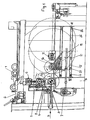
- FIG. 1 shows a system according to the invention
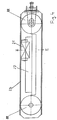
- FIG. 2 shows a section 1, 3 a section from FIG. 1,
- FIG. 4 a Section along line IV-IV in Fig. 1
- Fig. 5 shows a section along line V-V 4
- FIG. 6 shows a section along line VI-VI in FIG. 4
- FIG. 7 shows a section Section according to circle VII in Fig. 6.
- the winding shaft (drum) 1 is via a lowering device 2 inserted in the primary arm 3 and hydraulically vertical clamped over the drum 4.
- a Geared motor 6, which is arranged on a plate in the axial direction is assembled. This is coupled to the winding shaft 1 to this to bring up to machine speed.
- the primary arm 3 is now moved around by means of a swivel device 7 the axis of the support drum 4 rotated until the winding shaft 1 on it touches down.
- the winding shaft 1 takes over with the help of a suitable one Device the paper web P in full width and starts winding it up and increases its diameter.
- the required contact pressure between winding shaft 1 and carrier drum 4 is via hydraulic cylinder 8, which are equipped with a force measuring device, applied and regulated. This also compensates for the weight of the winding shaft 1 considered.
- the primary arm 3 is now further around the axis of the Carrier drum 4 pivoted until the winding shaft 1 in a horizontal position comes.
- the thickness of the paper roll increases continuously to a maximum 350 mm too.
- the outer part of the primary arm 3 moves telescopic to the outside. It is guided on roller bearings 9 to the To keep the influence of friction on the nip force as low as possible.
- the paper wrap is placed on a horizontally displaceable holding device 11 and clamped.
- Fig. 2 shows a section along line II-II in Fig. 1.
- the holding device 11 consists of a receiving part 12 with two hydraulically actuated clamping levers 13, 14 and sits on a force measuring device 16 which in turn is mounted on the sliding part 17.
- the entire unit is also called the secondary arm 30.
- a gear motor 18 which can be displaced in the axial direction the holding device 11 connected.
- this drive 18 on the drive side TS to the The winding shaft 1 is coupled and the drive 6 in the primary arm 3 is disengaged.
- the Secondary arm 30 the horizontal nip force (contact force between Drum 1 and idler 4) via a hydraulic cylinder 19 on the driver's side FS and drive side TS generated and via the force measuring devices regulated.
- Primary arm 3 prepared the next winding shaft 1. Once the paper wrap has reached the desired size, it is supported by the carrying drum 4 pulled away, the new winding shaft 1 in the primary arm 3 in the winding position placed on the carrying drum 4 and the full paper web P taken over. After ejecting the finished paper roll from the Secondary arm 30 moves back to carrier drum 4 and takes over then the new winding shaft 1 from the primary arm 3.
- the force measuring devices 16 are designed in such a way that they only apply those actually applied Horizontal forces in the nip between drum 1 and carrier drum 4 to capture. Vertical components from the drives or from the changed The weight of the paper roll affects the measured values Not.
- the measured value signals control the movement of the two Hydraulic cylinder 19, so that it is ensured that an absolute parallel operation of the secondary arms 30 on the driver's side FS and drive side TS and a Preselected nip force curve (constant or variable) over the entire Winding process is secured.
- the sliding part 17 of the secondary arm 30 is mounted on horizontally running support rollers 21, also here to keep the influences of friction low.
- FIG. 3 now shows a detail from FIG. 1, which represents the secondary arm 30.
- One can here the support roller 4 and winding shaft 1 with one Detect partially wrapped paper wraps.
- the contact pressure A can use the force measuring device 16 independently of the Position and lossless can be measured as there are no lossy ones Intermediate elements are present.
- the sliding part 17 of the secondary arm 30 through the hydraulic cylinders 19 shifted, so that always the same contact pressure A of Winding shaft 1 acts against the support roller 4.
- the respective position of the Secondary arm 30 is thereby by measuring systems integrated in the cylinders 19 detected.
- deflection rollers 22 In total 8 deflection rollers for one system, whereby a roller 22 can be tensioned.
- Deflection rollers 22 runs an endless belt 23 made of fabric, plastic or Steel.
- the support rollers 21 On this belt 23, the support rollers 21 are attached, here only one idler roller 21 is shown as an example.
- Fig. 5 shows a section along line V-V in Fig. 4, here the Structure of the support rollers 21 can be seen.
- the support rollers 21 run on Rails 27.
- On the top and bottom surfaces 28 of the Guide profile 26 recognizable. You can also turn on the endless belt 23 which the support rollers 21 are attached to and on the other side as well moved closely along the wall surfaces 28 of the guide profile 26 will recognize well.
- Fig. 6 now shows a section along line VI-VI in Fig. 4, through a Deflection roller 22 is placed.
- the deflection rollers 22 are with, for example Provided two trapezoidal grooves, 23 on the endless belt, for example also two trapezoidal profiles 24 are applied, which are in the grooves the deflecting rollers 22 engage and thus prevent lateral running.
- the number of grooves can vary depending on the bandwidth.
- FIG. 7 shows a section VII in FIG. 6. It can be seen very clearly here lateral slots 25 on the wall 28 of the guide profile 26 for Guide the tapes 23 and serve as a seal. In addition, the cavity 29 created by this device by continuous blowing protected from compressed air from dust.
Landscapes
- Winding Of Webs (AREA)
- Replacement Of Web Rolls (AREA)
- Paper (AREA)
- Controlling Rewinding, Feeding, Winding, Or Abnormalities Of Webs (AREA)
Abstract
Description
Claims (9)
- Vorrichtung zum kontinuierlichen Aufwickeln einer Faserstoffbahn, insbesondere Papier- beispielsweise Tissuebahn, wobei die Bahn über eine Tragtrommel geführt und in weiterer Folge auf einem Tambour aufgewickelt wird, mit einer horizontal verschiebbaren Haltevorrichtung, dadurch gekennzeichnet, dass die horizontal verschiebbare Haltevorrichtung (11) mit Tragrollen (21) versehen ist, die in Führungsprofilen (26) laufen, wobei die Führungsprofile (26) durch ein vertikal laufendes Band (23) abgedichtet sind.
- Vorrichtung nach Anspruch 1, dadurch gekennzeichnet, dass das vertikal laufende Band (23) als Endlosband ausgeführt ist und über zwei an den Enden der Führungsprofile (26) vorgesehenen Umlenkrollen (22) verläuft.
- Vorrichtung nach Anspruch 2, dadurch gekennzeichnet, dass das Endlosband (23) aus Gewebe, Kunststoff oder Stahl besteht.
- Vorrichtung nach Anspruch 2 oder 3, dadurch gekennzeichnet, dass die Umlenkrollen (22) Trapeznuten zur Führung des Bandes (23) aufweisen, wobei das Endlosband (23) mindestens ein trapezförmiges Profil (24) aufweist, das in die Trapeznuten der Umlenkrollen (22) eingreift.
- Vorrichtung nach einem der Ansprüche 1 bis 4, dadurch gekennzeichnet, dass zur Führung des Bandes (23) Schlitze (25) vorgesehen sind, die die Bandkanten umschließen.
- Vorrichtung nach einem der Ansprüche 1 bis 5, dadurch gekennzeichnet, dass der Hohlraum (29) zwischen Führungsprofil (26) und Band (23) durch Druckluft beaufschlagbar ist.
- Vorrichtung nach einem der Ansprüche 1 bis 6, dadurch gekennzeichnet, dass die Haltevorrichtung (11) eine Kraftmesseinrichtung (16) aufweist.
- Vorrichtung nach einem der Ansprüche 1 bis 7, dadurch gekennzeichnet, dass die verschiebbare Haltevorrichtung (11) mit Druckzylindern (19), insbesondere Hydraulikzylindern verbunden ist.
- Vorrichtung nach Anspruch 8, dadurch gekennzeichnet, dass die Druckzylinder (19) mit einer Regel- und/oder Steuereinrichtung verbunden sind.
Applications Claiming Priority (2)
| Application Number | Priority Date | Filing Date | Title |
|---|---|---|---|
| AT0010501A AT409852B (de) | 2001-01-22 | 2001-01-22 | Vorrichtung zum kontinuierlichen aufwickeln einer faserstoffbahn |
| AT1052001 | 2001-01-22 |
Publications (3)
| Publication Number | Publication Date |
|---|---|
| EP1225143A2 true EP1225143A2 (de) | 2002-07-24 |
| EP1225143A3 EP1225143A3 (de) | 2004-04-14 |
| EP1225143B1 EP1225143B1 (de) | 2006-08-02 |
Family
ID=3622916
Family Applications (1)
| Application Number | Title | Priority Date | Filing Date |
|---|---|---|---|
| EP01130578A Expired - Lifetime EP1225143B1 (de) | 2001-01-22 | 2001-12-21 | Vorrichtung zum kontinuierlichen Aufwickeln einer Faserstoffbahn |
Country Status (8)
| Country | Link |
|---|---|
| US (1) | US6669819B2 (de) |
| EP (1) | EP1225143B1 (de) |
| AT (1) | AT409852B (de) |
| CA (1) | CA2367178A1 (de) |
| DE (1) | DE50110610D1 (de) |
| ES (1) | ES2269289T3 (de) |
| MX (1) | MXPA02000743A (de) |
| PT (1) | PT1225143E (de) |
Cited By (3)
| Publication number | Priority date | Publication date | Assignee | Title |
|---|---|---|---|---|
| EP1460010A3 (de) * | 2003-03-19 | 2005-11-16 | Voith Paper Patent GmbH | Maschine mit einem vorzugsweise als Synchronmotor ausgeführten und zum Direktantrieb eines Wickelkerns einer Wickelrolle dienenden Elektromotors, insbesondere zur Verwendung in der Papierindustrie, und sich hierauf beziehendes Umbauverfahren |
| EP1764326A3 (de) * | 2005-09-15 | 2008-05-28 | Voith Patent GmbH | Antriebseinheit für eine Wickelmaschine zum Wickeln einer Materialbahn |
| EP1764325A3 (de) * | 2005-09-14 | 2008-10-22 | Voith Patent GmbH | Wickelmaschine zum Aufwickeln einer Materialbahn |
Families Citing this family (5)
| Publication number | Priority date | Publication date | Assignee | Title |
|---|---|---|---|---|
| FI117552B (fi) * | 2003-06-17 | 2006-11-30 | Metso Paper Inc | Menetelmä rullauksessa ja kiinnirullain |
| US6913223B2 (en) * | 2003-07-30 | 2005-07-05 | Metso Paper, Inc. | Paper machine reel-up with reel nip loading measurement |
| DE10342020A1 (de) * | 2003-09-12 | 2005-04-07 | Voith Paper Patent Gmbh | Wickelmaschine zum Wickeln einer Materialbahn |
| FI121229B (fi) * | 2005-07-08 | 2010-08-31 | Metso Paper Inc | Menetelmä hihnarullaimessa ja hihnarullain |
| CN112706464B (zh) * | 2019-10-26 | 2023-01-20 | 江苏亚振电力有限公司 | 一种自动上料加工的绝缘皱纹纸管加工装置 |
Family Cites Families (12)
| Publication number | Priority date | Publication date | Assignee | Title |
|---|---|---|---|---|
| DE9006554U1 (de) * | 1990-06-09 | 1991-01-17 | Bahr, Dirk, 4952 Porta Westfalica | Auf einem Führungsrohr längsverschiebbar gelagerter Aufnahmeschlitten |
| SE469071B (sv) * | 1991-09-18 | 1993-05-10 | Valmet Karlstad Ab | Rullstol med centrumdriven upprullningsvals |
| US5875990A (en) * | 1996-12-16 | 1999-03-02 | Valmet-Karlstad Ab | Reel-up |
| SE509107C2 (sv) * | 1997-04-21 | 1998-12-07 | Valmet Karlstad Ab | Rullstol med dubbla sekundärenheter |
| DE19748995A1 (de) * | 1997-11-06 | 1999-05-12 | Voith Sulzer Papiertech Patent | Verfahren und Wickelmaschine zum kontinuierlichen Aufwickeln einer Materialbahn |
| US5845868A (en) * | 1997-07-03 | 1998-12-08 | Valmet-Karlstad Ab | Apparatus and method for winding paper |
| US6098510A (en) * | 1997-09-19 | 2000-08-08 | Kimberly-Clark Worldwide, Inc. | Method and apparatus for slitting a sheet material web |
| DE19807897A1 (de) * | 1998-02-25 | 1999-08-26 | Voith Sulzer Papiertech Patent | Verfahren und Vorrichtung zum kontinuierlichen Aufwickeln einer Materialbahn |
| FI110259B (fi) * | 1998-05-07 | 2002-12-31 | Metso Paper Inc | Menetelmä ja laite rullan kuormittamiseksi rainan rullaimessa |
| FI110424B (fi) * | 1998-06-18 | 2003-01-31 | Metso Paper Inc | Rullain ja menetelmä rainan rullaamiseksi |
| US6427938B1 (en) * | 1998-10-22 | 2002-08-06 | Voith Sulzer Papiertechnik Patent Gmbh | Process and apparatus for cutting a running material web |
| US6036137A (en) * | 1998-12-17 | 2000-03-14 | Valmet-Karlstad Ab | Apparatus and method for winding paper |
-
2001
- 2001-01-22 AT AT0010501A patent/AT409852B/de not_active IP Right Cessation
- 2001-12-21 PT PT01130578T patent/PT1225143E/pt unknown
- 2001-12-21 DE DE50110610T patent/DE50110610D1/de not_active Expired - Lifetime
- 2001-12-21 ES ES01130578T patent/ES2269289T3/es not_active Expired - Lifetime
- 2001-12-21 EP EP01130578A patent/EP1225143B1/de not_active Expired - Lifetime
-
2002
- 2002-01-10 CA CA002367178A patent/CA2367178A1/en not_active Abandoned
- 2002-01-16 US US10/047,623 patent/US6669819B2/en not_active Expired - Fee Related
- 2002-01-21 MX MXPA02000743A patent/MXPA02000743A/es active IP Right Grant
Cited By (3)
| Publication number | Priority date | Publication date | Assignee | Title |
|---|---|---|---|---|
| EP1460010A3 (de) * | 2003-03-19 | 2005-11-16 | Voith Paper Patent GmbH | Maschine mit einem vorzugsweise als Synchronmotor ausgeführten und zum Direktantrieb eines Wickelkerns einer Wickelrolle dienenden Elektromotors, insbesondere zur Verwendung in der Papierindustrie, und sich hierauf beziehendes Umbauverfahren |
| EP1764325A3 (de) * | 2005-09-14 | 2008-10-22 | Voith Patent GmbH | Wickelmaschine zum Aufwickeln einer Materialbahn |
| EP1764326A3 (de) * | 2005-09-15 | 2008-05-28 | Voith Patent GmbH | Antriebseinheit für eine Wickelmaschine zum Wickeln einer Materialbahn |
Also Published As
| Publication number | Publication date |
|---|---|
| US20020104629A1 (en) | 2002-08-08 |
| ES2269289T3 (es) | 2007-04-01 |
| US6669819B2 (en) | 2003-12-30 |
| MXPA02000743A (es) | 2002-09-19 |
| DE50110610D1 (de) | 2006-09-14 |
| EP1225143A3 (de) | 2004-04-14 |
| AT409852B (de) | 2002-12-27 |
| ATA1052001A (de) | 2002-04-15 |
| CA2367178A1 (en) | 2002-07-22 |
| EP1225143B1 (de) | 2006-08-02 |
| PT1225143E (pt) | 2006-12-29 |
Similar Documents
| Publication | Publication Date | Title |
|---|---|---|
| DE69528224T2 (de) | Gerät und Verfahren zum berührungslosen aktiven Spannen von sich bewegendem bandförmigem Material | |
| EP0192982B1 (de) | Treibapparat für Walzband | |
| DE1279577B (de) | Einrichtung zum Ausfuehren von Arbeiten in einem Bohrloch ohne Bohrturm | |
| DE19607349A1 (de) | Verfahren und Vorrichtung zum Aufwickeln einer Papierbahn zu einer Rolle | |
| DE102013002022B4 (de) | Vorrichtung zum Wickeln eines strangförmigen Wickelguts und Verfahren dazu | |
| CH663602A5 (de) | Verfahren zum wickeln von erzeugnissen aus flexiblem material und wickelvorrichtung zur ausfuehrung des verfahrens. | |
| DE2349577A1 (de) | Wickelvorrichtung fuer fadenmaterial | |
| DE3042383A1 (de) | Glaettvorrichtung | |
| EP1225143B1 (de) | Vorrichtung zum kontinuierlichen Aufwickeln einer Faserstoffbahn | |
| DE4418900A1 (de) | Wickelmaschine zum Aufwickeln einer laufenden Papierbahn | |
| DE102013002019B4 (de) | Wickelungsvorrichtung für ein strangförmiges Wickelgut und Verfahren dazu | |
| DE102012214803A1 (de) | Vorrichtung zur Übergabe von Metallband | |
| DE3024133A1 (de) | Foerder- und/oder stapelvorrichtung | |
| DE69807755T2 (de) | Druckwarenwickler und wickelverfahren | |
| DE2853548C2 (de) | Vorrichtung zum vertikalen Nachführen der Führungsschlitten für die Achse von Wickelrollen beim Aufwickeln von Bahnen | |
| EP1225142B2 (de) | Verfahren und Vorrichtung zum kontinuierlichen Aufwickeln einer Faserstoffbahn | |
| EP0439830A2 (de) | Vorrichtung zur Be- oder Verarbeitung einer Materialbahn | |
| EP0093301B1 (de) | Vorrichtung zum Austauschen eines mit Wickelgut bewickelten Wickelkerns | |
| EP1225141B1 (de) | Vorrichtung zum kontinuierlichen Aufwickeln einer Faserstoffbahn | |
| AT409853B (de) | Vorrichtung zum kontinuierlichen aufwickeln einer faserstoffbahn | |
| DE4204550A1 (de) | Steuerung der bahnspannung einer bewegten materialbahn | |
| DE102019217682A1 (de) | Vorrichtung und Verfahren zum Transportieren von Bandmaterial, insbesondere Warmband | |
| DE69918429T2 (de) | Vorrichtung und verfahren zum aufbringen einer last auf eine rolle beim aufrollen einer papierbahn | |
| DE69831280T2 (de) | Verfahren und Vorrichtung zum Anbringen einer Materialschicht auf eine zu beschichtende Platte, vorzugsweise auf eine Glasscheibe | |
| DE60109323T2 (de) | Vorrichtung und verfahren zum wickeln von bahnen |
Legal Events
| Date | Code | Title | Description |
|---|---|---|---|
| PUAI | Public reference made under article 153(3) epc to a published international application that has entered the european phase |
Free format text: ORIGINAL CODE: 0009012 |
|
| AK | Designated contracting states |
Kind code of ref document: A2 Designated state(s): AT BE CH CY DE DK ES FI FR GB GR IE IT LI LU MC NL PT SE TR |
|
| AX | Request for extension of the european patent |
Free format text: AL;LT;LV;MK;RO;SI |
|
| PUAL | Search report despatched |
Free format text: ORIGINAL CODE: 0009013 |
|
| AK | Designated contracting states |
Kind code of ref document: A3 Designated state(s): AT BE CH CY DE DK ES FI FR GB GR IE IT LI LU MC NL PT SE TR |
|
| AX | Request for extension of the european patent |
Extension state: AL LT LV MK RO SI |
|
| RIC1 | Information provided on ipc code assigned before grant |
Ipc: 7B 65H 19/22 B Ipc: 7F 16C 29/08 B Ipc: 7B 65H 18/00 A |
|
| 17P | Request for examination filed |
Effective date: 20040825 |
|
| AKX | Designation fees paid |
Designated state(s): AT BE CH CY DE DK ES FI FR GB GR IE IT LI LU MC NL PT SE TR |
|
| GRAP | Despatch of communication of intention to grant a patent |
Free format text: ORIGINAL CODE: EPIDOSNIGR1 |
|
| GRAS | Grant fee paid |
Free format text: ORIGINAL CODE: EPIDOSNIGR3 |
|
| GRAA | (expected) grant |
Free format text: ORIGINAL CODE: 0009210 |
|
| AK | Designated contracting states |
Kind code of ref document: B1 Designated state(s): AT BE CH CY DE DK ES FI FR GB GR IE IT LI LU MC NL PT SE TR |
|
| PG25 | Lapsed in a contracting state [announced via postgrant information from national office to epo] |
Ref country code: GB Free format text: LAPSE BECAUSE OF FAILURE TO SUBMIT A TRANSLATION OF THE DESCRIPTION OR TO PAY THE FEE WITHIN THE PRESCRIBED TIME-LIMIT Effective date: 20060802 Ref country code: NL Free format text: LAPSE BECAUSE OF FAILURE TO SUBMIT A TRANSLATION OF THE DESCRIPTION OR TO PAY THE FEE WITHIN THE PRESCRIBED TIME-LIMIT Effective date: 20060802 Ref country code: IE Free format text: LAPSE BECAUSE OF FAILURE TO SUBMIT A TRANSLATION OF THE DESCRIPTION OR TO PAY THE FEE WITHIN THE PRESCRIBED TIME-LIMIT Effective date: 20060802 |
|
| REG | Reference to a national code |
Ref country code: GB Ref legal event code: FG4D Free format text: NOT ENGLISH |
|
| REG | Reference to a national code |
Ref country code: CH Ref legal event code: EP |
|
| REG | Reference to a national code |
Ref country code: IE Ref legal event code: FG4D Free format text: LANGUAGE OF EP DOCUMENT: GERMAN |
|
| REF | Corresponds to: |
Ref document number: 50110610 Country of ref document: DE Date of ref document: 20060914 Kind code of ref document: P |
|
| PG25 | Lapsed in a contracting state [announced via postgrant information from national office to epo] |
Ref country code: DK Free format text: LAPSE BECAUSE OF FAILURE TO SUBMIT A TRANSLATION OF THE DESCRIPTION OR TO PAY THE FEE WITHIN THE PRESCRIBED TIME-LIMIT Effective date: 20061102 |
|
| REG | Reference to a national code |
Ref country code: SE Ref legal event code: TRGR |
|
| REG | Reference to a national code |
Ref country code: PT Ref legal event code: SC4A Free format text: AVAILABILITY OF NATIONAL TRANSLATION Effective date: 20061031 |
|
| PG25 | Lapsed in a contracting state [announced via postgrant information from national office to epo] |
Ref country code: BE Free format text: LAPSE BECAUSE OF NON-PAYMENT OF DUE FEES Effective date: 20061231 Ref country code: CH Free format text: LAPSE BECAUSE OF NON-PAYMENT OF DUE FEES Effective date: 20061231 Ref country code: LI Free format text: LAPSE BECAUSE OF NON-PAYMENT OF DUE FEES Effective date: 20061231 Ref country code: MC Free format text: LAPSE BECAUSE OF NON-PAYMENT OF DUE FEES Effective date: 20061231 |
|
| NLV1 | Nl: lapsed or annulled due to failure to fulfill the requirements of art. 29p and 29m of the patents act | ||
| GBV | Gb: ep patent (uk) treated as always having been void in accordance with gb section 77(7)/1977 [no translation filed] |
Effective date: 20060802 |
|
| REG | Reference to a national code |
Ref country code: IE Ref legal event code: FD4D |
|
| REG | Reference to a national code |
Ref country code: ES Ref legal event code: FG2A Ref document number: 2269289 Country of ref document: ES Kind code of ref document: T3 |
|
| EN | Fr: translation not filed | ||
| PLBE | No opposition filed within time limit |
Free format text: ORIGINAL CODE: 0009261 |
|
| STAA | Information on the status of an ep patent application or granted ep patent |
Free format text: STATUS: NO OPPOSITION FILED WITHIN TIME LIMIT |
|
| 26N | No opposition filed |
Effective date: 20070503 |
|
| REG | Reference to a national code |
Ref country code: CH Ref legal event code: PL |
|
| BERE | Be: lapsed |
Owner name: ANDRITZ AG Effective date: 20061231 |
|
| PG25 | Lapsed in a contracting state [announced via postgrant information from national office to epo] |
Ref country code: AT Free format text: LAPSE BECAUSE OF NON-PAYMENT OF DUE FEES Effective date: 20061221 |
|
| PG25 | Lapsed in a contracting state [announced via postgrant information from national office to epo] |
Ref country code: GR Free format text: LAPSE BECAUSE OF FAILURE TO SUBMIT A TRANSLATION OF THE DESCRIPTION OR TO PAY THE FEE WITHIN THE PRESCRIBED TIME-LIMIT Effective date: 20061103 Ref country code: FR Free format text: LAPSE BECAUSE OF FAILURE TO SUBMIT A TRANSLATION OF THE DESCRIPTION OR TO PAY THE FEE WITHIN THE PRESCRIBED TIME-LIMIT Effective date: 20070511 |
|
| PG25 | Lapsed in a contracting state [announced via postgrant information from national office to epo] |
Ref country code: LU Free format text: LAPSE BECAUSE OF NON-PAYMENT OF DUE FEES Effective date: 20061221 Ref country code: TR Free format text: LAPSE BECAUSE OF FAILURE TO SUBMIT A TRANSLATION OF THE DESCRIPTION OR TO PAY THE FEE WITHIN THE PRESCRIBED TIME-LIMIT Effective date: 20060802 |
|
| PG25 | Lapsed in a contracting state [announced via postgrant information from national office to epo] |
Ref country code: FR Free format text: LAPSE BECAUSE OF FAILURE TO SUBMIT A TRANSLATION OF THE DESCRIPTION OR TO PAY THE FEE WITHIN THE PRESCRIBED TIME-LIMIT Effective date: 20060802 Ref country code: CY Free format text: LAPSE BECAUSE OF FAILURE TO SUBMIT A TRANSLATION OF THE DESCRIPTION OR TO PAY THE FEE WITHIN THE PRESCRIBED TIME-LIMIT Effective date: 20060802 |
|
| PGFP | Annual fee paid to national office [announced via postgrant information from national office to epo] |
Ref country code: ES Payment date: 20091222 Year of fee payment: 9 Ref country code: FI Payment date: 20091215 Year of fee payment: 9 Ref country code: SE Payment date: 20091214 Year of fee payment: 9 |
|
| PGFP | Annual fee paid to national office [announced via postgrant information from national office to epo] |
Ref country code: PT Payment date: 20091216 Year of fee payment: 9 |
|
| PGFP | Annual fee paid to national office [announced via postgrant information from national office to epo] |
Ref country code: IT Payment date: 20091223 Year of fee payment: 9 |
|
| PGFP | Annual fee paid to national office [announced via postgrant information from national office to epo] |
Ref country code: DE Payment date: 20091222 Year of fee payment: 9 |
|
| REG | Reference to a national code |
Ref country code: PT Ref legal event code: MM4A Free format text: LAPSE DUE TO NON-PAYMENT OF FEES Effective date: 20110621 |
|
| PG25 | Lapsed in a contracting state [announced via postgrant information from national office to epo] |
Ref country code: PT Free format text: LAPSE BECAUSE OF NON-PAYMENT OF DUE FEES Effective date: 20110621 |
|
| PG25 | Lapsed in a contracting state [announced via postgrant information from national office to epo] |
Ref country code: FI Free format text: LAPSE BECAUSE OF NON-PAYMENT OF DUE FEES Effective date: 20101221 |
|
| REG | Reference to a national code |
Ref country code: SE Ref legal event code: EUG |
|
| PG25 | Lapsed in a contracting state [announced via postgrant information from national office to epo] |
Ref country code: SE Free format text: LAPSE BECAUSE OF NON-PAYMENT OF DUE FEES Effective date: 20101222 |
|
| REG | Reference to a national code |
Ref country code: DE Ref legal event code: R119 Ref document number: 50110610 Country of ref document: DE Effective date: 20110701 |
|
| PG25 | Lapsed in a contracting state [announced via postgrant information from national office to epo] |
Ref country code: DE Free format text: LAPSE BECAUSE OF NON-PAYMENT OF DUE FEES Effective date: 20110701 |
|
| PG25 | Lapsed in a contracting state [announced via postgrant information from national office to epo] |
Ref country code: IT Free format text: LAPSE BECAUSE OF NON-PAYMENT OF DUE FEES Effective date: 20101221 |
|
| REG | Reference to a national code |
Ref country code: ES Ref legal event code: FD2A Effective date: 20120305 |
|
| PG25 | Lapsed in a contracting state [announced via postgrant information from national office to epo] |
Ref country code: ES Free format text: LAPSE BECAUSE OF NON-PAYMENT OF DUE FEES Effective date: 20101222 |