EP1225319A2 - Dispositif de commande pour le circuit de refroidissement d'un moteur à combustion interne - Google Patents
Dispositif de commande pour le circuit de refroidissement d'un moteur à combustion interne Download PDFInfo
- Publication number
- EP1225319A2 EP1225319A2 EP01126742A EP01126742A EP1225319A2 EP 1225319 A2 EP1225319 A2 EP 1225319A2 EP 01126742 A EP01126742 A EP 01126742A EP 01126742 A EP01126742 A EP 01126742A EP 1225319 A2 EP1225319 A2 EP 1225319A2
- Authority
- EP
- European Patent Office
- Prior art keywords
- control device
- openings
- drain
- housing
- control
- Prior art date
- Legal status (The legal status is an assumption and is not a legal conclusion. Google has not performed a legal analysis and makes no representation as to the accuracy of the status listed.)
- Withdrawn
Links
Images

Classifications
-
- F—MECHANICAL ENGINEERING; LIGHTING; HEATING; WEAPONS; BLASTING
- F01—MACHINES OR ENGINES IN GENERAL; ENGINE PLANTS IN GENERAL; STEAM ENGINES
- F01P—COOLING OF MACHINES OR ENGINES IN GENERAL; COOLING OF INTERNAL-COMBUSTION ENGINES
- F01P7/00—Controlling of coolant flow
- F01P7/14—Controlling of coolant flow the coolant being liquid
- F01P7/16—Controlling of coolant flow the coolant being liquid by thermostatic control
-
- F—MECHANICAL ENGINEERING; LIGHTING; HEATING; WEAPONS; BLASTING
- F02—COMBUSTION ENGINES; HOT-GAS OR COMBUSTION-PRODUCT ENGINE PLANTS
- F02B—INTERNAL-COMBUSTION PISTON ENGINES; COMBUSTION ENGINES IN GENERAL
- F02B75/00—Other engines
- F02B75/16—Engines characterised by number of cylinders, e.g. single-cylinder engines
- F02B75/18—Multi-cylinder engines
- F02B75/22—Multi-cylinder engines with cylinders in V, fan, or star arrangement
-
- F—MECHANICAL ENGINEERING; LIGHTING; HEATING; WEAPONS; BLASTING
- F16—ENGINEERING ELEMENTS AND UNITS; GENERAL MEASURES FOR PRODUCING AND MAINTAINING EFFECTIVE FUNCTIONING OF MACHINES OR INSTALLATIONS; THERMAL INSULATION IN GENERAL
- F16K—VALVES; TAPS; COCKS; ACTUATING-FLOATS; DEVICES FOR VENTING OR AERATING
- F16K11/00—Multiple-way valves, e.g. mixing valves; Pipe fittings incorporating such valves
- F16K11/02—Multiple-way valves, e.g. mixing valves; Pipe fittings incorporating such valves with all movable sealing faces moving as one unit
- F16K11/08—Multiple-way valves, e.g. mixing valves; Pipe fittings incorporating such valves with all movable sealing faces moving as one unit comprising only taps or cocks
- F16K11/085—Multiple-way valves, e.g. mixing valves; Pipe fittings incorporating such valves with all movable sealing faces moving as one unit comprising only taps or cocks with cylindrical plug
- F16K11/0856—Multiple-way valves, e.g. mixing valves; Pipe fittings incorporating such valves with all movable sealing faces moving as one unit comprising only taps or cocks with cylindrical plug having all the connecting conduits situated in more than one plane perpendicular to the axis of the plug
-
- F—MECHANICAL ENGINEERING; LIGHTING; HEATING; WEAPONS; BLASTING
- F02—COMBUSTION ENGINES; HOT-GAS OR COMBUSTION-PRODUCT ENGINE PLANTS
- F02B—INTERNAL-COMBUSTION PISTON ENGINES; COMBUSTION ENGINES IN GENERAL
- F02B75/00—Other engines
- F02B75/16—Engines characterised by number of cylinders, e.g. single-cylinder engines
- F02B75/18—Multi-cylinder engines
- F02B2075/1804—Number of cylinders
- F02B2075/1824—Number of cylinders six
Definitions
- the invention relates to a control device for the Cooling circuit of an internal combustion engine with at least two coolant sub-circuits, in particular for a V-engine with two cylinder banks.
- a control device is known from DE 198 09 124 A1 for the cooling and heating circuit of an internal combustion engine known, in which a rotary valve as a control arranged within a valve housing is.
- An inlet opening leads in the axial direction into the housing and it branches in the radial direction three drain openings.
- DE 44 16 039 C1 describes a control valve, in which by means of a rotary valve trained valve body optionally with an inlet up to three processes can be connected.
- Fig. 1 shows a schematic representation of an internal combustion engine 1 in V design with two cylinder banks 2 and 3, in which in a known manner in In the present case there are six combustion chambers 4.
- the Internal combustion engine 1 is also with itself known cooling circuit 5, in which a Cooler 6 and a water pump 7 are integrated.
- the Water pump 7 pumps through mutually independent lines 8 and 9 coolant to the cylinder banks 2 and 3 of the internal combustion engine 1, each not shown Include cylinder heads.
- the cooling circuit 5 10 there is a control device in the cooling circuit 5 10 provided, in which two of the cylinder banks 2 and 3 outgoing lines 11 and 12 lead.
- the two lines 11 and 12 form the connection from two separate coolant partial flows cylinder banks 2 and 3 with the rest of the cooling circuit 5.
- a line 13 to the water pump 7 and a line 14 to the cooler 6.
- the cooler 6 with the water pump 7 via another Line 15 connected.
- the cooling circuit 5 for the Internal combustion engine 1 is thus through lines 8, 9, 11, 12, 13, 14 and 15 are formed.
- a heating circuit for the internal combustion engine 1 may be provided, but this will be described below not detailed.
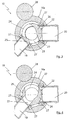
- FIGs 2 to 6 show the structure of the control device 10, which is used to control the flow within of the cooling circuit 5 is provided. So points the control device 10 on a housing 16, which with at least two radially entering inlet openings 17 and 18 and at least one also radial emerging outlet openings is provided. In the present Embodiment are two drain openings 19 and 20 provided. Both the inlet openings occur 17 and 18 as well as the drain openings 19 and 20 into the control device via a peripheral wall 16a 10 in or out of the same. From the inlet openings 17 and 18 is in a manner not shown and One with one of the lines 11 and 12, respectively connected, whereas from the drain openings 19 and 20 the lines 13 and 14 go out.
- the inlet openings 17 and 18 can be different or are on a common level, from one another level for the drain openings 19 and 20 is different.
- the drain openings 19 and 20 can deviate from the present representation, lie in different levels. Alternatively, that would be it is also possible to axial the inlet openings 17 and 18 to enter the housing 16.
- the housing 16 is provided with a cover 21.
- a Control element 22 which in the present case as Rotary valve is designed and a not shown Thermostatic valve or a temperature sensor can be controlled.
- the structure of the control element 22 can be seen more clearly from FIGS. 3 to 6.
- the control element 22 has two openings on its circumference 23 and 24 and two each between the openings 23 and 24 lying barrier walls 25 and 26.
- the barrier walls 25 and 26 are facing inwards Pages built so that they are able to direct the coolant flow and so only a small one Represent flow resistance.
- drain opening 19 and barrier wall 26 closes the drain opening 20.
- the Width or the angle over which the barrier walls 25 and 26 run each chosen such that this the drain openings 19 and 20 are completely blocked can, so that the control device 10 according to FIG. 3 is completely closed and no coolant flows.
- the opening 23 in the control element is correct 22 matches or is with the drain opening 19 the same congruent and so that can over the Inlet openings 17 and 18 flowing in the coolant Leave drain opening 19.
- the drain opening 19 is in the present case as a short-circuit opening for one Short circuit through the two cylinder banks 2 and 3 formed so that in the position shown of the control element 22, a flow in this short circuit prevails. It can be seen that the Size of the opening 23 at least approximately the size corresponds to the drain opening 19, which in particular favorable flow behavior and loss optimization within the coolant flow leads.
- the barrier wall 26 is designed such that it the drain opening 20 is still in this position closes.
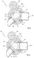
- a position of the control element rotated by a total of approximately 85 ° 22 shows Fig. 5, which results in both the drain opening 19 and the drain opening 20, which leads to a cooler circuit of the internal combustion engine 1 leads and thus designed as a radiator opening is partially open. This can be done via the inlet openings 17 and 18 flowing into the housing 16 Coolant through both drain openings 19 and 20 flow out and it arises in the cooling circuit 5 a so-called mixed operation.
- the barrier wall 25 has here, just like in the position according to FIG. 4, none Function, whereas the barrier wall 26, the two drain openings 19 and 20 partially closed.
- the size and shape of the opening 24 is at least approximately corresponds to the size and shape of the drain opening 20.
- the openings 23 and 24 are therefore incorrect only in their angle they around the circumference of the control 22 take with the drain openings 19 and 20 match, but also in their amount.
- the barrier wall 26 closes the outlet opening 19 and prevents it thus an outflow of the coolant into the same. To the Control element 22 reached this position rotated by approximately 150 ° by means of the drive device 28.
- the openings are around the circumference of the control element 22 23 and 24 and the intervening barrier walls 25 and 26 thus distributed so that when the drain opening 19 is completely open, the drain opening 20 completely is closed and vice versa.
- Switch positions of the control device 10 are thereby can be approached individually and independently of one another, whereby is prevented that coolant inadvertently in a wrong line arrives.
- the reset of the control 22 is done counterclockwise.
- control device 10 shows two inlet openings 17 and 18 as well two drain openings 19 and 20. If necessary, it would be also possible, further inlet and / or outlet openings to provide, then in particular in the case of further Drain openings control 22 with others Openings and other barrier walls may be provided would.
Landscapes
- Engineering & Computer Science (AREA)
- General Engineering & Computer Science (AREA)
- Mechanical Engineering (AREA)
- Chemical & Material Sciences (AREA)
- Combustion & Propulsion (AREA)
- Cylinder Crankcases Of Internal Combustion Engines (AREA)
- Multiple-Way Valves (AREA)
Applications Claiming Priority (2)
| Application Number | Priority Date | Filing Date | Title |
|---|---|---|---|
| DE2001101826 DE10101826B4 (de) | 2001-01-17 | 2001-01-17 | Steuervorrichtung für den Kühlkreislauf einer Brennkraftmaschine |
| DE10101826 | 2001-01-17 |
Publications (2)
| Publication Number | Publication Date |
|---|---|
| EP1225319A2 true EP1225319A2 (fr) | 2002-07-24 |
| EP1225319A3 EP1225319A3 (fr) | 2004-05-12 |
Family
ID=7670768
Family Applications (1)
| Application Number | Title | Priority Date | Filing Date |
|---|---|---|---|
| EP01126742A Withdrawn EP1225319A3 (fr) | 2001-01-17 | 2001-11-09 | Dispositif de commande pour le circuit de refroidissement d'un moteur à combustion interne |
Country Status (2)
| Country | Link |
|---|---|
| EP (1) | EP1225319A3 (fr) |
| DE (1) | DE10101826B4 (fr) |
Cited By (4)
| Publication number | Priority date | Publication date | Assignee | Title |
|---|---|---|---|---|
| WO2012034617A1 (fr) * | 2010-09-13 | 2012-03-22 | Audi Ag | Circuit de liquide de refroidissement pour un moteur à combustion interne |
| ITBS20130149A1 (it) * | 2013-10-22 | 2015-04-23 | Ind Saleri Italo Spa | Gruppo valvola estraibile con otturatore migliorato |
| CN105597961A (zh) * | 2014-11-13 | 2016-05-25 | 亚智科技股份有限公司 | 喷涂装置及其喷涂切换方法 |
| CN107664232A (zh) * | 2016-07-29 | 2018-02-06 | 认知控管株式会社 | 多方向转换阀装置及其制造方法 |
Families Citing this family (5)
| Publication number | Priority date | Publication date | Assignee | Title |
|---|---|---|---|---|
| DE10249449B4 (de) * | 2002-10-24 | 2005-12-08 | Pierburg Gmbh | Bypass-Ventilvorrichtung |
| DE102006038213B4 (de) * | 2006-08-16 | 2010-11-11 | Itw Automotive Products Gmbh & Co. Kg | Thermostatventil |
| DE102009035349B4 (de) | 2009-07-30 | 2018-06-28 | BorgWarner Esslingen GmbH | Steuervorrichtung für den Kühlmittelfluss im Kühlkreislauf einer Brennkraftmaschine |
| DE102014110706A1 (de) * | 2014-07-29 | 2016-02-18 | Mahle International Gmbh | Ventil |
| DE102016116361B3 (de) * | 2016-05-03 | 2017-06-29 | Borgwarner Ludwigsburg Gmbh | Steuervorrichtung für den Kühlmittelfluss in einem Kühlkreislauf einer Brennkraftmaschine |
Citations (4)
| Publication number | Priority date | Publication date | Assignee | Title |
|---|---|---|---|---|
| DE4416039C1 (de) | 1994-05-06 | 1995-08-31 | Freudenberg Carl Fa | Regelventil |
| DE19809124A1 (de) | 1998-03-04 | 1999-09-16 | Daimler Chrysler Ag | Steuervorrichtung für den Kühl- und Heizungskreislauf einer Brennkraftmaschine |
| EP0947750A2 (fr) | 1998-04-03 | 1999-10-06 | Cemi Piscine Service S.r.l. | Robinet à papillon à trois voies |
| EP0961060A1 (fr) | 1998-05-28 | 1999-12-01 | Vygon | Robinet à boisseau et à clé tournante à voies de communication multiples |
Family Cites Families (4)
| Publication number | Priority date | Publication date | Assignee | Title |
|---|---|---|---|---|
| US2628060A (en) * | 1945-05-15 | 1953-02-10 | Parker Appliance Co | Rotary plug valve seat |
| GB624416A (en) * | 1945-09-19 | 1949-06-08 | Jose Juan Cordova | Improvements in or relating to valves |
| DE19849492B4 (de) * | 1998-10-27 | 2005-12-22 | Daimlerchrysler Ag | Steuervorrichtung für einen Kühlkreislauf einer Brennkraftmaschine |
| DE19925010A1 (de) * | 1999-05-25 | 2000-11-30 | Ingmar Bergmann | Mehrfach-Dreiwege-Mischer |
-
2001
- 2001-01-17 DE DE2001101826 patent/DE10101826B4/de not_active Expired - Lifetime
- 2001-11-09 EP EP01126742A patent/EP1225319A3/fr not_active Withdrawn
Patent Citations (4)
| Publication number | Priority date | Publication date | Assignee | Title |
|---|---|---|---|---|
| DE4416039C1 (de) | 1994-05-06 | 1995-08-31 | Freudenberg Carl Fa | Regelventil |
| DE19809124A1 (de) | 1998-03-04 | 1999-09-16 | Daimler Chrysler Ag | Steuervorrichtung für den Kühl- und Heizungskreislauf einer Brennkraftmaschine |
| EP0947750A2 (fr) | 1998-04-03 | 1999-10-06 | Cemi Piscine Service S.r.l. | Robinet à papillon à trois voies |
| EP0961060A1 (fr) | 1998-05-28 | 1999-12-01 | Vygon | Robinet à boisseau et à clé tournante à voies de communication multiples |
Cited By (7)
| Publication number | Priority date | Publication date | Assignee | Title |
|---|---|---|---|---|
| WO2012034617A1 (fr) * | 2010-09-13 | 2012-03-22 | Audi Ag | Circuit de liquide de refroidissement pour un moteur à combustion interne |
| ITBS20130149A1 (it) * | 2013-10-22 | 2015-04-23 | Ind Saleri Italo Spa | Gruppo valvola estraibile con otturatore migliorato |
| WO2015059586A1 (fr) * | 2013-10-22 | 2015-04-30 | Industrie Saleri Italo S.P.A. | Groupe de vannes extractible à obturateur et pompe améliorés |
| CN105814315A (zh) * | 2013-10-22 | 2016-07-27 | 萨乐锐伊塔洛工业有限公司 | 具有改进的封闭器的可取出的阀组以及泵 |
| CN105597961A (zh) * | 2014-11-13 | 2016-05-25 | 亚智科技股份有限公司 | 喷涂装置及其喷涂切换方法 |
| CN107664232A (zh) * | 2016-07-29 | 2018-02-06 | 认知控管株式会社 | 多方向转换阀装置及其制造方法 |
| CN107664232B (zh) * | 2016-07-29 | 2019-06-28 | 认知控管株式会社 | 多方向转换阀装置及其制造方法 |
Also Published As
| Publication number | Publication date |
|---|---|
| DE10101826B4 (de) | 2006-12-21 |
| EP1225319A3 (fr) | 2004-05-12 |
| DE10101826A1 (de) | 2002-07-25 |
Similar Documents
| Publication | Publication Date | Title |
|---|---|---|
| DE202019005792U1 (de) | Mehrwege-Mehrebenenventil | |
| DE102018009680A9 (de) | Massenstromsteuerungseinheit sowie Kühlmittelsystem mit zumindest einer solchen Massenstromsteuerungseinheit | |
| DE102019128897A1 (de) | Mehrwegeventil, Fluidkreislauf und Kühlfluidkreislauf | |
| DE2622041C2 (de) | Umschaltventil | |
| DE102017211891A1 (de) | Ventilanordnung für einen Kältemittelkreislauf | |
| DE102020202520A1 (de) | Verteilventil und Kühlsystem | |
| DE3300217A1 (de) | Stroemungssteuerungsventil | |
| DE102013209582A1 (de) | Drehschieberkugel für ein Thermomanagementmodul | |
| EP4165333A1 (fr) | Distributeur et cage pour un distributeur | |
| DE2707134C2 (fr) | ||
| DE102007054137A1 (de) | Hydraulische Ventilvorrichtung | |
| DE4324939C2 (de) | Kolbenschieberventil | |
| EP1225319A2 (fr) | Dispositif de commande pour le circuit de refroidissement d'un moteur à combustion interne | |
| DE112021006785T5 (de) | Mehrwegeventil und Wärmemanagementsystem mit einem solchen Ventil | |
| EP0393345A2 (fr) | Dispositif de commande hydraulique | |
| DE102021113817A1 (de) | Kugelventil mit mehrwinkliger dichtung für kühlmittelregler | |
| DE10014555C2 (de) | Steuervorrichtung für den Kühlkreislauf einer Brennkraftmaschine | |
| WO2006116999A1 (fr) | Garniture de soupape de distribution, soupape de distribution et module de soupape | |
| EP1120553B1 (fr) | Soupape, notamment une soupape thermostatique | |
| DE4107604C2 (de) | Vollhydraulische Lenkeinheit | |
| DE68910431T2 (de) | Fluidsteuerventil. | |
| DE212016000145U1 (de) | Ventilanordnung für eine Pumpe mit einer verbesserten Regulierung des Durchtritts einer Kühlflüssigkeit | |
| DE2251478A1 (de) | Wegeventil | |
| EP0123088B1 (fr) | Valve hydraulique directionnelle pour la commande d'un servomoteur à double effet | |
| DE102006039480A1 (de) | Mehrwegeventil, insbesondere für ein Fahrzeug-Heiz/Kühl-System |
Legal Events
| Date | Code | Title | Description |
|---|---|---|---|
| PUAI | Public reference made under article 153(3) epc to a published international application that has entered the european phase |
Free format text: ORIGINAL CODE: 0009012 |
|
| AK | Designated contracting states |
Kind code of ref document: A2 Designated state(s): AT BE CH CY DE DK ES FI FR GB GR IE IT LI LU MC NL PT SE TR |
|
| AX | Request for extension of the european patent |
Free format text: AL;LT;LV;MK;RO;SI |
|
| PUAL | Search report despatched |
Free format text: ORIGINAL CODE: 0009013 |
|
| AK | Designated contracting states |
Kind code of ref document: A3 Designated state(s): AT BE CH CY DE DK ES FI FR GB GR IE IT LI LU MC NL PT SE TR |
|
| AX | Request for extension of the european patent |
Extension state: AL LT LV MK RO SI |
|
| 17P | Request for examination filed |
Effective date: 20041023 |
|
| AKX | Designation fees paid |
Designated state(s): DE FR GB |
|
| RAP1 | Party data changed (applicant data changed or rights of an application transferred) |
Owner name: GUSTAV WAHLER GMBH U. CO.KG Owner name: DAIMLERCHRYSLER AG |
|
| 17Q | First examination report despatched |
Effective date: 20070614 |
|
| RAP1 | Party data changed (applicant data changed or rights of an application transferred) |
Owner name: GUSTAV WAHLER GMBH U. CO.KG Owner name: DAIMLER AG |
|
| STAA | Information on the status of an ep patent application or granted ep patent |
Free format text: STATUS: THE APPLICATION HAS BEEN WITHDRAWN |
|
| 18W | Application withdrawn |
Effective date: 20080315 |