EP1225432A2 - Dispositif de surveillance de longueur d'onde - Google Patents
Dispositif de surveillance de longueur d'onde Download PDFInfo
- Publication number
- EP1225432A2 EP1225432A2 EP02001278A EP02001278A EP1225432A2 EP 1225432 A2 EP1225432 A2 EP 1225432A2 EP 02001278 A EP02001278 A EP 02001278A EP 02001278 A EP02001278 A EP 02001278A EP 1225432 A2 EP1225432 A2 EP 1225432A2
- Authority
- EP
- European Patent Office
- Prior art keywords
- photo
- detector
- reflector
- light
- beam splitter
- Prior art date
- Legal status (The legal status is an assumption and is not a legal conclusion. Google has not performed a legal analysis and makes no representation as to the accuracy of the status listed.)
- Withdrawn
Links
Images


Classifications
-
- G—PHYSICS
- G01—MEASURING; TESTING
- G01J—MEASUREMENT OF INTENSITY, VELOCITY, SPECTRAL CONTENT, POLARISATION, PHASE OR PULSE CHARACTERISTICS OF INFRARED, VISIBLE OR ULTRAVIOLET LIGHT; COLORIMETRY; RADIATION PYROMETRY
- G01J9/00—Measuring optical phase difference; Determining degree of coherence; Measuring optical wavelength
- G01J9/02—Measuring optical phase difference; Determining degree of coherence; Measuring optical wavelength by interferometric methods
Definitions
- the present invention relates to wavelength monitors, which are typically used in the field of optical measurement technology to measure the wavelengths of light sources oscillating in a single mode.
- DFB-LD distributed feedback laser diode
- DBR-LD distributed Bragg reflector laser diode
- DWDM dense wavelength division multiplexing
- Wavelength tunable light sources of an external resonator type using a diffraction grating are extensively used to measure the wavelength characteristics of optical components. While they are capable of setting a desired value of wavelength over a broad range ( ⁇ 100 nm), this type of light sources are sensitive to external effects and temperature changes in particular affect the wavelength stability. In addition, as the DWDM system becomes adaptive to higher degrees of multiplexing, it is required to increase the probability that the light source has stable wavelengths.
- spectroscopes such as an optical spectrum analyzer that rotate a diffraction grating by a moving mechanism.
- wavelength locker is used to control the wavelength of a DFB-LD light source with a structure that uses optical components such as interference film based filters and diffraction gratings.
- the wavelength monitor called a wavelength locker can only be operated over a narrow wavelength range but using no mechanical moving parts, it has high reliability, can be reduced in size, requires no large-scale processing with software and, hence, is suited to the purpose of controlling the wavelengths of light sources such as one for DBF-LD that seldom vary in wavelength. There is, however, a problem in that the operating wavelength is limited by the wavelength characteristics of the components used such as filters.
- a conventional wavelength monitor that is free from this problem may be a "wavelength change measuring apparatus" disclosed in JP 11-034697 A.
- a block diagram for the configuration of this apparatus is shown in Fig. 6 as a reference for the following description of the apparatus.
- Measuring light emerging from the input fiber 201 is collimated and launched into the beam splitter 203 as the first splitting means provided on the axis of the emerging light, whereby it is split into two beams, one directed toward the first reflector 204 and the other toward the second reflector 205.
- the first reflector 204 and the second reflector 205 are provided normal to the optical paths of the split beams of collimated light emerging from the beam splitter 203 and their optical axes are adjusted such that each of the split beams of collimated light will be reflected back to the beam splitter 203 by travelling through the same optical path.
- the two beams of collimated light that have been reflected by the first reflector 204 and the second reflector 205 make a second entry into the beam splitter 203, where they are recombined before entering the reflecting prism 206 as the second splitting means.
- the reflecting prism 206 is provided such that the axial plane where the pathlength difference of ⁇ 0 /4 has been generated coincides with the edge tip surface of the reflecting prism 206; the recombined parallel light incident on the reflecting prism 206 is split into two beams by its edge tip surface and the split beams are launched into the first photo-detector 207 and the second photo-detector 208 which are provided on their optical axes.
- the light beams entering the two photo-detectors are output to the signal processing circuit 209 as currents that depend on their optical intensity.
- the signal processing circuit 209 compares the light intensities from the two photo-detectors and perform necessary arithmetic operations to output wavelength data.
- I signifies the normalized light intensity received by a photo-detector
- ⁇ is the wavelength of the light input from the light source
- ⁇ L is the pathlength difference in the Michelson interferometer.
- interference light intensity signals with a phase difference of ⁇ /2, one can determine the amounts and directions of changes in the wavelength of a light source.
- the present invention has been accomplished to solve the aforementioned problems of the conventional and its principal object is to provide a low-cost wavelength monitor for measuring the wavelength of a single mode oscillating light source with such a design that a phase difference of ⁇ /2 is generated in two interference light intensity signals without using any specially designed optical components and that the phase difference can be adjusted after fixing the individual optical components.
- a wavelength monitor comprising:
- a wavelength monitor comprising:
- a wavelength monitor comprising:
- a wavelength monitor comprising:
- a wavelength monitor comprising:
- interference light intensity signals having a phase difference are produced by the means of generating an interference pattern in an interference light beam plane, so the specially designed reflector (step mirror) which has been used in the conventional wavelength monitors is no longer necessary, making it possible to realize cost reduction by parts standardization.
- slits narrower than the spacing between interference fringes are positioned in front of the photo-detectors for light reception and this provides interference light intensity characteristics having almost ideal changes in light intensity.
- the reflected light from neither of the two reflectors returns to the input section, thereby insulating it from any adverse effects.
- the wavelength monitors have no need to use a third beam splitter and, hence, can be constructed at lower cost in smaller size.
- said interference pattern generating means may be realized by inclining said first reflector and/or said second reflector.
- said interference pattern generating means may be realized by inserting a wedge substrate into one of the two optical paths in said optical system.
- said interference pattern generating means may be realized by inclining said first beam splitter and/or said second beam splitter.
- said first slit and/or said second slit may be variable in slit width.
- said first slit and/or said second slit may be variable in slit position.
- light reception may be effected by said first photo-detector and/or said second photo-detector which have a detecting area diameter smaller than the diameter of interference beams and said first photo-detector and/or said second photo-detector is variable in position.
- the slit position By adjusting the slit position, some latitude is provided in the control of light intensity.
- the width and position of the slit provided in front of each photo-detector are adjusted to produce interference electro-optic signals having an ideal phase difference.
- Wavelength monitors according to the first to fifth embodiments of the invention are described with reference to Figs. 1 - 5.
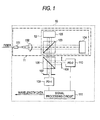
- Fig. 1 is a diagram showing configuration of a wavelength monitor 10 according to the first embodiment of the invention.
- the wavelength monitor 10 has a Michelson interferometer optical system 11 comprising a collimating lens (optical element) 102 for collimating the incident light from an input fiber (light input section) 101, a first beam splitter 103 for splitting the incident collimated light from the optical element 102 into two beams, and a first reflector 104 and a second reflector 105 for reflecting the respective split beams of collimated light from the first beam splitter 103.
- a Michelson interferometer optical system 11 comprising a collimating lens (optical element) 102 for collimating the incident light from an input fiber (light input section) 101, a first beam splitter 103 for splitting the incident collimated light from the optical element 102 into two beams, and a first reflector 104 and a second reflector 105 for reflecting the respective split beams of collimated light from the first beam splitter 103.
- the optical system 11 has an interference pattern generating means 12 which inclines the wavefronts of the reflected beams from the first reflector 104 and the second reflector 105 after they are recombined at the first beam splitter 103, thereby generating an interference pattern in the light intensity distribution in an interference light beam plane, and this interference pattern generating means 12 is realized by inclining the first reflector 104 and/or the second reflector 105.
- the optical system 11 further includes a second beam splitter 106, a first slit 107 and a second slit 108, as well as a first photo-detector 109 and a second photo-detector 110 that are securely provided on an optical base platform (not shown); another component of the optical system 11 is a signal processing circuit (signal processing means) 111 for processing the signals from the first photo-detector 109 and the second photo-detector 110.
- a signal processing circuit signal processing means
- the input fiber 101 guides the light from a light source (not shown) and emits it from the end face.
- the lens 102 is provided on the optical axis of the light emerging from the input fiber 101 and collimates the light emerging from the end face of the fiber.
- the emerging collimated light from the lens 102 is launched into the first beam splitter 103 provided on its optical axis.
- the first beam splitter 103 splits the incident light into two beams, one being directed to the first reflector 104 and the other directed to the second reflector 105.
- the first reflector 104 is provided on the optical path of one of the two beams of collimated light from the first beam splitter 103 and reflects the incident beam of collimated light such that it makes a second entry into the first beam splitter 103.
- the second reflector 105 is provided on the optical path of the other of the two beams of collimated light from the first beam splitter 103 and reflects the incident beam of collimated light such that it makes a second entry into the first beam splitter 103.
- the two beams of collimated light reflected by the first reflector 104 and the second reflector 105 to make a second entry into the first beam splitter 103 are recombined and emerge from said first beam splitter 103 it at two end faces, one facing the input fiber 101 and the other being different from the first end face.
- the intensity of the light emerging from the first end face and that of the light emerging from the second end face have inverting characteristics.
- the reflected beam from the first reflector 104 and the reflected beam from the second reflector 105 that are to be recombined at the first beam splitter 103 have their optical axes adjusted to incline slightly.
- the second beam splitter 106 Adjacent the second end face of the first beam splitter 103 which is different from the first one which faces the input fiber 101, there is provided the second beam splitter 106 on the optical axis of the emerging light.
- the second beam splitter 106 splits the incident interference light into two beams, one being directed to the first photo-detector 109 and the other directed to the second photo-detector 110.
- One of the two split beams of interference light emerging from the second beam splitter 106 is launched into the first photo-detector 109 after passing through the first slit 107 provided on its optical axis.
- the other of the two split beams of interference light is launched into the second photo-detector 110 after passing through the second slit 108 provided on its optical axis.
- the collimated light is directly launched into the photo-detectors but it will be apparent to the skilled artisan that the collimated light may first be condensed with another lens (not shown) before it is received by the photo-detectors.
- the first photo-detector 109 and the second photo-detector 110 may each be composed of a photodiode and after converting light to electrical signals, they output currents in accordance with the intensity of the received light.
- the electrical signals proportional to the intensities of light from the first photo-detector 109 and the second photo-detector 110 are compared and subjected to necessary arithmetic operations so that the wavelength of the incident light is determined and wavelength data is output.
- the system is so designed that the reflected beam from the first reflector 104 and the reflected beam from the second reflector 105 that are to be recombined at the first beam splitter 103 have their optical axes adjusted to incline (to realize the interference pattern generating means 12).
- the wavefronts of the two beams of reflected parallel light are inclined and the intensity of light in the interference light beam plane does not have the uniformity expressed by eq. 1; instead, linear interference fringes are generated.
- the interference fringes under observation appear to make a parallel shift in response to the wavelength change.
- the positions of the first slit 107 and the second slit 108 provided in front of the first photo-detector 109 and the second photo-detector 110, respectively, are adjusted, thereby making it possible to adjust the phase difference between the interference light intensity signals being output from the two photo-detectors.
- the widths and positions of the slits provided in front of the first photo-detector 109 and the second photo-detector 110 are adjusted and this has the advantage that the phase difference in the light intensity signals from the two photo-detectors as determined by fixing the individual optical elements can be controlled to produce interference light intensity signals having an ideal phase difference.
- step mirror which has been used in the conventional wavelength monitors is no longer necessary, contributing to cost reduction.
- the diffraction occurring at the boundary between the step and the non-step area of the step mirror is structurally absent from the design of the embodiment under consideration and there is no such problem as the occurrence of distorted interference optical signals.
- Fig. 2 is a diagram showing the configuration of a wavelength monitor 20 according to the second embodiment of the invention.
- the components which are the same as those shown in Fig. 1 are identified by the same numerals.
- the wavelength monitor 20 of the second embodiment has a Mach-Zehnder interferometer optical system 21 comprising a collimating lens (optical element) 102 for collimating the incident light from an input fiber (light input section) 101, a first beam splitter 103 for splitting the incident collimated light from the optical element 102 into two beams, a first reflector 104 and a second reflector 105 for reflecting the respective split beams of collimated light from the first beam splitter 103, and a second beam splitter 106 for recombining the reflected beams of light.
- a Mach-Zehnder interferometer optical system 21 comprising a collimating lens (optical element) 102 for collimating the incident light from an input fiber (light input section) 101, a first beam splitter 103 for splitting the incident collimated light from the optical element 102 into two beams, a first reflector 104 and a second reflector 105 for reflecting the respective split beams of collimated light from the first beam splitter 103,
- the optical system 21 has an interference pattern generating means 22 which inclines the wavefronts of the reflected beams from the first reflector 104 and the second reflector 105 after they are recombined at the second beam splitter 106, thereby generating an interference pattern in the light intensity distribution in an interference light beam plane, and this interference pattern generating means 22 is realized either by inclining the first reflector 104 and/or the second reflector 105 or by inclining the first beam splitter 103 and/or the second beam splitter 106.
- the optical system 21 further includes a third beam splitter 112, a first slit 107 and a second slit 108, as well as a first photo-detector 109 and a second photo-detector 110 that are securely provided on an optical base platform (not shown); another component of the optical system 21 is a signal processing circuit (signal processing means) 111 for processing the signals from the first photo-detector 109 and the second photo-detector 110.
- a signal processing circuit signal processing means
- the first reflector 104 - is provided on the optical path of one of the two beams of collimated light from the first beam splitter 103 and reflects the incident beam of collimated light to be launched into the second beam splitter 106.
- the second reflector 105 is provided on the optical path of the other of the two beams of collimated light from the first beam splitter 103 and reflects the incident beam of collimated light to be launched into the second beam splitter 106.
- the two beams of collimated light reflected by the first reflector 104 and the second reflector 105 to be launched into the second beam splitter 106 are recombined and emerge from said second beam splitter 106 at two end faces that differ from the two incident end faces.
- the reflected beam from the first reflector 104 and the reflected beam from the second reflector 105 that are to be recombined at the second beam splitter 106 have their optical axes adjusted to incline slightly. These two optical axes can be inclined by means of either the reflectors or the beam splitter and either method will do.
- the third beam splitter 112 is provided on the optical axis of the light emerging from one of the two exit end faces of the second beam splitter 106.
- the light intensities emerging from the two exit end faces of the second beam splitter 106 have inverting characteristics but the third beams splitter 112 may be provided adjacent whichever of the two exit end faces.
- the third beam splitter 112 splits the incident interference light into two beams, one being directed to the first photo-detector 109 and the other directed to the second photo-detector 110.
- One of the two split beams of interference light emerging from the third beam splitter 112 is launched into the first photo-detector 109 after passing through the first slit 107 provided on its optical axis.
- the other of the two split beams of interference light is launched into the second photo-detector 110 after passing through the second slit 108 provided on its optical axis.
- the subsequent operations are the same as in the first embodiment.
- the second embodiment described above has the same advantage as the first embodiment, it offers another advantage in that the reflected light from neither the first reflector 104 nor the second reflector 105 returns to the input fiber 101, thereby insulating it from any adverse effects.
- Fig. 3 is a diagram showing the configuration of a wavelength monitor 30 according to the third embodiment of the invention.
- the components which are the same as those shown in Figs. 1 and 2 are identified by the same numerals.
- the wavelength monitor 30 of the third embodiment has a Mach-Zehnder interferometer optical system 31 comprising a collimating lens (optical element) 102 for collimating the incident light from an input fiber (light input section) 101, a first beam splitter 103 for splitting the incident collimated light into two beams, a first reflector 104 and a second reflector 105 for reflecting the respective split beams of collimated light from the first beam splitter 103, and a second beam splitter 106 for recombining the two beams of reflected light.
- a collimating lens (optical element) 102 for collimating the incident light from an input fiber (light input section) 101
- a first beam splitter 103 for splitting the incident collimated light into two beams
- a first reflector 104 and a second reflector 105 for reflecting the respective split beams of collimated light from the first beam splitter 103
- a second beam splitter 106 for recombining the two beams of reflected light.
- the optical system 31 has an interference pattern generating means 32 which inclines the wavefronts of the reflected beams from the first reflector 104 and the second reflector 105 after they are recombined at the second beam splitter 106, thereby generating an interference pattern in the light intensity distribution in an interference light beam plane, and this interference pattern generating means 32 is realized either by inclining the first reflector 104 and/or the second reflector 105 or by inclining the first beam splitter 103 and/or the second beam splitter 106.
- the optical system 31 further includes a first slit 107 and a second slit 108, as well as a first photo-detector 109 and a second photo-detector 110 that are securely provided on an optical base platform (not shown); another component of the optical system 31 is a signal processing circuit (signal processing means) 111 for processing the signals from the first photo-detector 109 and the second photo-detector 110.
- a signal processing circuit signal processing means
- the operations up to the stage of recombining the reflected beams at the second beam splitter 106 are the same as in the second embodiment.
- the second beam splitter 106 recombines the two beams of reflected parallel light from the first reflector 104 and the second reflector 105 and allows them to emerge from two end faces that differ from the two incident end faces.
- One of the two split beams of interference light emerging from the second beam splitter 106 is launched into the first photo-detector 109 after passing through the first slit 107 provided on its optical axis.
- the other of the two split beams of interference light is launched into the second photo-detector 110 after passing through the second slit 108 provided on its optical axis.
- the light intensities emerging from the two exit end faces of the second beam splitter 106 have inverting characteristics.
- the positions of the first and second slits provided on the optical axes of the beams emerging from the second beam splitter 106 are different from their positions on the optical axes of the beams emerging from the third beam splitter 112 in the aforementioned second embodiment.
- the third beam splitter 112 in the second embodiment can be eliminated and this contributes to reducing cost and size.
- Fig. 4 is a diagram showing the configuration of a wavelength monitor 40 according to the fourth embodiment of the invention.
- the components which aro the same as those shown in Figs. 1 - 3 are identified by the same numerals.
- the wavelength monitor 40 of the fourth embodiment has a Mach-Zehnder interferometer optical system 41 comprising a collimating lens (optical element) 102 for collimating the incident light from an input fiber (light input section) 101, a first beam splitter 103 for splitting the incident collimated light into two beams, a first reflector 104 for reflecting one of the two beams of collimated light as split by the first beam splitter 103, a second reflector 105 for reflecting the collimated light reflected from the first reflector 104, and a second beam splitter 106 for recombining the other of the two beams of collimated light as split by the first beam splitter 103 with the reflected light from the second reflector 105.
- a Mach-Zehnder interferometer optical system 41 comprising a collimating lens (optical element) 102 for collimating the incident light from an input fiber (light input section) 101, a first beam splitter 103 for splitting the incident collimated light into two beams, a
- the optical system 41 has an interference pattern generating means 42 which inclines the wavefront of the reflected light from the second reflector after recombination of beams by the second beam splitter 106 and the wavefront of the other of the two beams of collimated light as split by the first beam splitter 103, thereby generating an interference pattern in the light intensity distribution in an interference light beam plane, and this interference pattern generating means 42 is realized either by inclining the first reflector 104 and/or the second reflector 105 or by inclining the first beam splitter 103 and/or the second beam splitter 106.
- the optical system 41 further includes a third beam splitter 112, a first slit 107 and a second slit 108, as well as a first photo-detector 109 and a second photo-detector 110 that are securely provided on an optical base platform (not shown); another component of the optical system 41 is a signal processing circuit (signal processing means) 111 for processing the signals from the first photo-detector 109 and the second photo-detector 110.
- a signal processing circuit signal processing means
- the first reflector 104 is provided on the optical path of one of the two split beams of collimated light from the first beam splitter 103 and reflects the incident beam of collimated light toward the second reflector 105.
- the second reflector 105 is provided on the optical path of the collimated light reflected from the first reflector 104 and reflects the incident collimated light to be launched into the second beam splitter 106.
- the other of the two beams of collimated light as split by the first beam splitter 103 and the collimated light reflected from the second reflector 105 are launched into the second beam splitter 106, where they are recombined and emerge from two end faces that differ from the two incident end faces.
- the third beam splitter 112 is provided on the optical axis of the light emerging from the second beam splitter 106 at one of the two exit end faces.
- the light intensities emerging from the two exit end faces of the second beam splitter 106 have inverting characteristics but the third beam splitter 112 may be provided adjacent whichever of the two exit end faces.
- the fourth embodiment parallels the second embodiment in that the reflected light from neither the first reflector 104 nor the second reflector 105 returns to the input fiber 101, thereby insulating it from any adverse effects.
- an interferometer of the described design one can fabricate a wavelength monitor having a great difference in pathlength and offering narrow FSR wavelength characteristics.
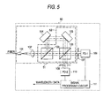
- Fig. 5 is a diagram showing the configuration of a wavelength monitor 50 according to the fifth embodiment of the invention.
- the components which are the same as those shown in Figs. 1 - 4 are identified by the same numerals.
- the wavelength monitor 50 of the fifth embodiment has a Mach-Zehnder interferometer optical system 51 comprising a collimating lens (optical element) 102 for collimating the incident light from an input fiber (light input section) 101, a first beam splitter 103 for splitting the incident collimated light from the optical element 102 into two beams, a first reflector 104 for reflecting one of the two beams of collimated light as split by the first beam splitter 103, a second reflector 105 for reflecting the collimated light reflected from the first reflector 104, and a second beam splitter 106 for recombining the other of the two beams of collimated light as split by the first beam splitter 103 with the reflected light from the second reflector 105.
- a Mach-Zehnder interferometer optical system 51 comprising a collimating lens (optical element) 102 for collimating the incident light from an input fiber (light input section) 101, a first beam splitter 103 for splitting the incident collimated light from
- the optical system 51 has an interference pattern generating means 52 which inclines the wavefront of the reflected light from the second reflector 105 after recombination of beams by the second beam splitter 106 and the wavefront of the other of the two beams of collimated light as split by the first beam splitter 103, thereby generating an interference pattern in the light intensity distribution in an interference light beam plane, and this interference pattern generating means 52 is realized either by inclining the first reflector 104 and/or the second reflector 105 or by inclining the first beam splitter 103 and/or the second beam splitter 106.
- the optical system 51 further includes a first slit 107 and a second slit 108, as well as a first photo-detector 109 and a second photo-detector 110 that are securely provided on an optical base platform (not shown); another component of the optical system 51 is a signal processing circuit (signal processing means) 111 for processing the signals from the first photo-detector 109 and the second photo-detector 110.
- a signal processing circuit signal processing means
- the operations up to the stage of recombining the reflected beams at the second beam splitter 106 are the same as in the fourth embodiment.
- the second beam splitter 106 recombines the other of the two beams of collimated light as split by the first beam splitter 103 with the collimated light reflected from the second reflector 105.
- the recombined beams emerge from the second beam splitter 106 at two end faces that differ from the two incident end faces.
- the third beam splitter 112 in the fourth embodiment can be eliminated and this contributes to reducing cost and size.
- the second beam splitter 106 in the first embodiment and the third beam splitter 112 in the second and fourth embodiments may employ the reflecting prism 206 (see Fig. 6) which is shown in JP 11-034697 A, "Wavelength Change Measuring Apparatus", and hereby incorporated as a conventional reference.
- Light may be reflected by the reflecting prism 206 to both sides as taught in JP 11-034697 A, supra but obviously, only one half of the beam diameter may be reflected.
- the interference pattern generating means may be realized by inserting a wedge substrate (such as a glass plate in wedge shape having one side formed at an angle with the other side) into one of the optical paths in the optical system.
- a wedge substrate such as a glass plate in wedge shape having one side formed at an angle with the other side
- the width and position of the slit provided in front of each photo-detector are adjusted after fixing the individual components and this has the advantage of producing interference light intensity signals having an ideal phase difference.
- the specially designed step mirror which has been used in the conventional wavelength monitors is no longer necessary, contributing to cost reduction. Since the diffraction occurring at the boundary between the step and the non-step area of the step mirror is absent, there is no such problem as the occurrence of distorted interference optical signals.
- the reflected light from neither of the two reflectors returns to the input fiber, thereby insulating the input section from any adverse effects.
- the wavelength monitors use a smaller number of components and, hence, can be constructed at lower cost in smaller size.
Landscapes
- Physics & Mathematics (AREA)
- Spectroscopy & Molecular Physics (AREA)
- General Physics & Mathematics (AREA)
- Spectrometry And Color Measurement (AREA)
- Instruments For Measurement Of Length By Optical Means (AREA)
Applications Claiming Priority (2)
| Application Number | Priority Date | Filing Date | Title |
|---|---|---|---|
| JP2001008589A JP2002214049A (ja) | 2001-01-17 | 2001-01-17 | 波長モニタ |
| JP2001008589 | 2001-01-17 |
Publications (2)
| Publication Number | Publication Date |
|---|---|
| EP1225432A2 true EP1225432A2 (fr) | 2002-07-24 |
| EP1225432A3 EP1225432A3 (fr) | 2004-12-01 |
Family
ID=18876187
Family Applications (1)
| Application Number | Title | Priority Date | Filing Date |
|---|---|---|---|
| EP02001278A Withdrawn EP1225432A3 (fr) | 2001-01-17 | 2002-01-17 | Dispositif de surveillance de longueur d'onde |
Country Status (3)
| Country | Link |
|---|---|
| US (1) | US6980297B2 (fr) |
| EP (1) | EP1225432A3 (fr) |
| JP (1) | JP2002214049A (fr) |
Cited By (3)
| Publication number | Priority date | Publication date | Assignee | Title |
|---|---|---|---|---|
| CN102679882A (zh) * | 2012-04-27 | 2012-09-19 | 夏豪杰 | 一种相位调制光栅传感器及实现测量的方法 |
| CN102768385A (zh) * | 2011-05-06 | 2012-11-07 | 菲尼萨公司 | 光信道监控器 |
| CN102983492A (zh) * | 2012-12-05 | 2013-03-20 | 中国科学院上海光学精密机械研究所 | 饱和吸收消多普勒加宽谱线的装置 |
Families Citing this family (26)
| Publication number | Priority date | Publication date | Assignee | Title |
|---|---|---|---|---|
| US20030072336A1 (en) * | 2001-09-13 | 2003-04-17 | Spectra-Physics Lasers, Inc. | Miniaturized internal laser stabilizing apparatus with inline output for fiber optic applications |
| US6765940B2 (en) * | 2001-11-01 | 2004-07-20 | Agility Communications, Inc. | Anamorphic prism wavelength locker |
| DE10202120A1 (de) * | 2002-01-21 | 2003-07-31 | Scinex Ag Zug | Interferometrische optische Anordnung |
| JP4214367B2 (ja) * | 2002-07-19 | 2009-01-28 | 横河電機株式会社 | 波長モニタ及びモータ駆動制御装置 |
| US7310153B2 (en) * | 2004-08-23 | 2007-12-18 | Palo Alto Research Center, Incorporated | Using position-sensitive detectors for wavelength determination |
| JP4600755B2 (ja) * | 2005-04-22 | 2010-12-15 | 横河電機株式会社 | 波長モニタ |
| JP4835908B2 (ja) * | 2005-06-10 | 2011-12-14 | 横河電機株式会社 | 光学特性測定装置 |
| JP4604878B2 (ja) * | 2005-06-27 | 2011-01-05 | 横河電機株式会社 | 波長モニタ |
| JP4604879B2 (ja) * | 2005-06-27 | 2011-01-05 | 横河電機株式会社 | 波長モニタ |
| DE102006028953B4 (de) * | 2005-06-27 | 2011-01-27 | Yokogawa Electric Corp., Musashino | Wellenlängenmonitor |
| US8437582B2 (en) | 2005-12-22 | 2013-05-07 | Palo Alto Research Center Incorporated | Transmitting light with lateral variation |
| US7718948B2 (en) * | 2006-12-04 | 2010-05-18 | Palo Alto Research Center Incorporated | Monitoring light pulses |
| KR100925783B1 (ko) * | 2007-09-07 | 2009-11-11 | 한국표준과학연구원 | 형상 측정장치 및 그 방법 |
| US8477296B2 (en) | 2010-04-12 | 2013-07-02 | University of Maribor | Opto-electronic signal processing methods, systems, and apparatus for optical sensor interrogation |
| US20130088708A1 (en) * | 2011-10-06 | 2013-04-11 | International Currency Technologies Corp. | Apparatus for optically detecting foreign object |
| CN106547055B (zh) * | 2015-09-23 | 2019-04-16 | 青岛海信宽带多媒体技术有限公司 | 一种光探测模组和光模块 |
| KR101797966B1 (ko) | 2016-10-19 | 2017-12-12 | 한국생산기술연구원 | 경사평면을 이용한 광원파장 측정 시스템 및 측정 방법 |
| CN106769898B (zh) * | 2016-12-29 | 2024-01-26 | 同方威视技术股份有限公司 | 多分辨率光谱仪 |
| CN108871594A (zh) * | 2017-05-09 | 2018-11-23 | 美国通用光电公司 | 基于光偏振分析的光频解码器及其光传感系统 |
| US10901241B1 (en) | 2018-03-14 | 2021-01-26 | Onto Innovation Inc. | Optical metrology system using infrared wavelengths |
| CN109443532B (zh) * | 2018-10-23 | 2020-07-24 | 北京工业大学 | 一种激光光场互相干系数测试装置 |
| JP7235955B2 (ja) * | 2019-01-11 | 2023-03-09 | 日本電信電話株式会社 | 波長モニタ装置および波長モニタ方法 |
| CN110426129B (zh) * | 2019-06-25 | 2021-01-15 | 太原理工大学 | 一种基于光子干涉测量不同光场互相关的装置及方法 |
| US11525750B2 (en) * | 2019-07-31 | 2022-12-13 | Ut-Battelle, Llc | Metal-embedded optical fibers for monitoring pressure or corrosion at high temperatures |
| US11988562B2 (en) * | 2021-04-08 | 2024-05-21 | Systems & Technology Research, Llc | Interferometer with at least one dispersive element |
| CN116576977B (zh) * | 2023-04-12 | 2025-09-30 | 华中光电技术研究所(中国船舶集团有限公司第七一七研究所) | 一种用于原子干涉仪的拉曼光干涉调节装置及调节方法 |
Family Cites Families (13)
| Publication number | Priority date | Publication date | Assignee | Title |
|---|---|---|---|---|
| US4280764A (en) * | 1980-02-21 | 1981-07-28 | The United States Of America As Represented By The Secretary Of The Navy | Phase-conjugate interferometer |
| IT1195127B (it) * | 1986-08-08 | 1988-10-12 | Cselt Centro Studi Lab Telecom | Interferometro eterodina tipo michelson per misure di polarizzazione |
| US4758090A (en) * | 1986-09-25 | 1988-07-19 | Allied-Signal Inc. | Optical wavelength monitor using blazed diffraction grating |
| JPH04161832A (ja) * | 1990-10-26 | 1992-06-05 | Olympus Optical Co Ltd | 光位相差測定法 |
| US5574557A (en) * | 1995-05-08 | 1996-11-12 | The Board Of Trustees Of The Leland Stanford Junior University | Apparatus and method for performing sub-poissonian interference measurements using an intensity-squeezed state |
| US5684545A (en) * | 1995-07-07 | 1997-11-04 | New Mexico State University Technology Transfer Corp. | Adaptive optics wave measurement and correction system |
| GB2311600A (en) * | 1996-03-29 | 1997-10-01 | Secr Defence | Optic Fibre Interferometric sensor |
| DE69706827T2 (de) * | 1997-05-02 | 2002-03-28 | Agilent Technologies Inc., A Delaware Corp. | Wellenlängenmessgerät und eine Einrichtung zur Regelung der Wellenlänge einer Lichtquelle |
| US5841536A (en) * | 1997-08-01 | 1998-11-24 | The United States Of America As Represented By The Director Of The National Security Agency | Polarization interferometer apparatus using the polarization dependent phase lag in a birefringent retarder |
| JP2000234959A (ja) * | 1999-02-12 | 2000-08-29 | Ando Electric Co Ltd | 波長変化測定器及び波長可変光源 |
| EP1158630B1 (fr) * | 2000-04-25 | 2006-12-06 | Avanex Corporation | Dispositif de stabilisation en longueur d'onde et méthode de réglage de la longueur d'onde de travail du dispositif |
| US6587214B1 (en) * | 2000-06-26 | 2003-07-01 | Jds Uniphase Corporation | Optical power and wavelength monitor |
| DE60001139T2 (de) * | 2000-08-16 | 2003-09-11 | Agilent Technologies, Inc. (N.D.Ges.D.Staates Delaware) | Wellenlängenmesser mit grober und feiner Messanlage |
-
2001
- 2001-01-17 JP JP2001008589A patent/JP2002214049A/ja not_active Withdrawn
-
2002
- 2002-01-17 US US10/051,507 patent/US6980297B2/en not_active Expired - Fee Related
- 2002-01-17 EP EP02001278A patent/EP1225432A3/fr not_active Withdrawn
Cited By (4)
| Publication number | Priority date | Publication date | Assignee | Title |
|---|---|---|---|---|
| CN102768385A (zh) * | 2011-05-06 | 2012-11-07 | 菲尼萨公司 | 光信道监控器 |
| CN102679882A (zh) * | 2012-04-27 | 2012-09-19 | 夏豪杰 | 一种相位调制光栅传感器及实现测量的方法 |
| CN102983492A (zh) * | 2012-12-05 | 2013-03-20 | 中国科学院上海光学精密机械研究所 | 饱和吸收消多普勒加宽谱线的装置 |
| CN102983492B (zh) * | 2012-12-05 | 2014-12-17 | 中国科学院上海光学精密机械研究所 | 饱和吸收消多普勒加宽谱线的装置 |
Also Published As
| Publication number | Publication date |
|---|---|
| EP1225432A3 (fr) | 2004-12-01 |
| US6980297B2 (en) | 2005-12-27 |
| US20020093660A1 (en) | 2002-07-18 |
| JP2002214049A (ja) | 2002-07-31 |
Similar Documents
| Publication | Publication Date | Title |
|---|---|---|
| US6980297B2 (en) | Wavelength monitor | |
| US6526079B1 (en) | Single etalon optical wavelength reference device | |
| US6043883A (en) | Wavemeter and an arrangement for the adjustment of the wavelength of the signals of an optical source | |
| US6937346B2 (en) | Wavemeter having two interference elements | |
| EP0867989B1 (fr) | Source de lumière à semi-conducteur à longueur d'onde accordable | |
| US7038782B2 (en) | Robust wavelength locker for control of laser wavelength | |
| US20030035120A1 (en) | Multiple-interferometer device for wavelength measuring and locking | |
| US6859284B2 (en) | Apparatus and method for determining wavelength from coarse and fine measurements | |
| JP2001257419A (ja) | 波長安定化レーザモジュール | |
| US7075656B2 (en) | Method and algorithm for continuous wavelength locking | |
| JPH11211571A (ja) | 波長測定装置 | |
| CN1609571B (zh) | 波长监测器 | |
| US6859469B2 (en) | Method and apparatus for laser wavelength stabilization | |
| US20020163643A1 (en) | Optical interference apparatus and method | |
| EP1028311A1 (fr) | Appareil pour la mesure de changements d'une longueur d'onde et source de lumiere à longueur d'onde variable | |
| KR20010073962A (ko) | 파장안정화를 위한 파장검출 및 안정화 방법과 이를이용한 파장안정화 광원모듈 | |
| JP4600755B2 (ja) | 波長モニタ | |
| JP2001345511A (ja) | 波長モニター | |
| JP4604879B2 (ja) | 波長モニタ | |
| JP2002340687A (ja) | 波長モニタ | |
| JP2024115237A (ja) | 光路長差計測装置および振動計測装置 | |
| JP2007121232A (ja) | 波長モニタ | |
| JPH11274643A (ja) | 可変波長半導体レーザ光源 | |
| JP2001208608A (ja) | 波長測定器 | |
| JP2001228023A (ja) | 波長変化測定器 |
Legal Events
| Date | Code | Title | Description |
|---|---|---|---|
| PUAI | Public reference made under article 153(3) epc to a published international application that has entered the european phase |
Free format text: ORIGINAL CODE: 0009012 |
|
| AK | Designated contracting states |
Kind code of ref document: A2 Designated state(s): AT BE CH CY DE DK ES FI FR GB GR IE IT LI LU MC NL PT SE TR |
|
| AX | Request for extension of the european patent |
Free format text: AL;LT;LV;MK;RO;SI |
|
| PUAL | Search report despatched |
Free format text: ORIGINAL CODE: 0009013 |
|
| AK | Designated contracting states |
Kind code of ref document: A3 Designated state(s): AT BE CH CY DE DK ES FI FR GB GR IE IT LI LU MC NL PT SE TR |
|
| AX | Request for extension of the european patent |
Extension state: AL LT LV MK RO SI |
|
| STAA | Information on the status of an ep patent application or granted ep patent |
Free format text: STATUS: THE APPLICATION IS DEEMED TO BE WITHDRAWN |
|
| 18D | Application deemed to be withdrawn |
Effective date: 20040803 |