EP1225433A2 - Capteur de pression électronique - Google Patents
Capteur de pression électronique Download PDFInfo
- Publication number
- EP1225433A2 EP1225433A2 EP02250208A EP02250208A EP1225433A2 EP 1225433 A2 EP1225433 A2 EP 1225433A2 EP 02250208 A EP02250208 A EP 02250208A EP 02250208 A EP02250208 A EP 02250208A EP 1225433 A2 EP1225433 A2 EP 1225433A2
- Authority
- EP
- European Patent Office
- Prior art keywords
- pressure
- sensor
- module
- sensing
- fluid
- Prior art date
- Legal status (The legal status is an assumption and is not a legal conclusion. Google has not performed a legal analysis and makes no representation as to the accuracy of the status listed.)
- Withdrawn
Links
Images


Classifications
-
- G—PHYSICS
- G01—MEASURING; TESTING
- G01L—MEASURING FORCE, STRESS, TORQUE, WORK, MECHANICAL POWER, MECHANICAL EFFICIENCY, OR FLUID PRESSURE
- G01L19/00—Details of, or accessories for, apparatus for measuring steady or quasi-steady pressure of a fluent medium insofar as such details or accessories are not special to particular types of pressure gauges
- G01L19/0007—Fluidic connecting means
Definitions
- This invention relates to an electronic pressure sensing device, and more particularly to such a device for use with fluid filters to determine pressure loss across the filter.
- Determining the pressure loss across a filter is an every day occurrence and is a very important factor in determining the filter element(s) potential life expectancy and also the costs associated with power consumption.
- a further enhancement of these mechanical devices is to attach a magnet to the moving parts and, at a pre-set differential pressure, have it coincide with an electrical reed switch thus opening up many options for an electrical interface.
- a still further enhancement includes a light fitted within the differential gauge casing such that it can send out a visual (flashing) warning when it reaches a pre-set differential pressure.
- This invention addresses the problems concerned with fitting such devices.
- an electronic pressure sensing device comprising a pressure sensing/transmitter module including at least one pressure sensor having a pair of opposed sensing elements, and a pair of inlet ports on the module to supply fluid under pressure to the sensing elements, the device further comprising a plurality of adaptors each having a pair of outlet ports for connection to the inlet ports on the module whereby each adaptor can be selectively coupled to the module, each adaptor being capable of being connected to a different configuration of pressurised fluid supply to feed the associated supply to at least one of the inlet ports on the module, the module further including electronic means for interpreting and transmitting the values of pressures sensed by the sensing elements.
- the sensing/transmitter modules may consist of a metal or plastic enclosure containing at least one piezoresistive sensor integrated with and sealed in a fluid tight manner to two sensor manifolds, one to each end of said sensor, which incorporate male connections with captive double O-ring seals which extend from the front of the module and with which pressure tight connection to any of the adapters may be made.
- each sensor manifold may be ported (drilled) in various ways to allow the sensing/transmitter module to operate in at least three different measurement formats by allowing the pressure, directed by the adapters from the application, to be directed to the appropriate sensor pressure port.
- Said module may contain all the necessary circuitry with which to accept a 12-24 VDC electric power input and to output a current or voltage signal directly proportional to the pressure being measured with an accuracy greater than 1 ⁇ 2% of the pressure range being measured.
- An integrated electrical connector provides means with which to make input and output electrical connections while maintaining an IP65 seal.
- a yellow LED may extend from the rear of the case to give a positive indication of power supply to the device.
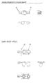
- the sensor manifolds 2,3 may be ported in at least four different ways to allow the manifolds to be used in three different finished sensing/transmitter module product configurations, 1,6,15.
- both manifolds 2,3 are drilled from the front port 73,74, through to the first sensor cavity therefore exposing one end 4 of the sensor 29 to the higher of two pressures and the second end 5 of the sensor 29 to the lower of two pressures.
- one manifold 7 is drilled from the front port through to the first sensor cavity 13 therefore exposing one end 8 of the sensor 36 to pressure.
- the second manifold 14 is drilled from the outside of the case 9 through to the first sensor cavity 10 so that the second end 12 of the sensor 36 is exposed to atmospheric pressure. Since the pressure port 11 of the second manifold is not drilled through to the first sensor cavity 10, the sensor's low pressure port 11 is isolated from pressure and therefore allows the device to read gauge pressure.
- the first manifold 16 is drilled from the front port 17 through to both sensor cavities 18,19 so that one end 20,21 of both sensors 32,33 is exposed to the higher of two pressures.
- the second manifold 22 is drilled from the front port 23 through to the first sensor cavity 24 so that the second end 25 of the first sensor 32 is exposed to the lower of two pressures.
- a third hole is drilled from the outside of the case 26 into the second sensor cavity 27 such that the second end 28 of the second sensor 33 is exposed to atmospheric pressure. This allows the first sensor 32 to read differential pressure and the second sensor 33 to read gauge pressure.
- the device utilises up to two pressure sensors and one temperature sensor thereby allowing up to six different measurement formats each with its own current or voltage output.
- a pressure sensor in the first sensor manifold position to measure the difference in pressure between the upstream and downstream pressures. Additionally a temperature sensor allows measurement of the ambient temperature at the application.
- a pressure sensor in the first sensor manifold position to measure the upstream gauge pressure. Additionally a temperature sensor allows measurement of the ambient temperature at the application.
- a temperature sensor allows measurement of the ambient temperature at the application.
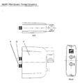
- the rear sensing unit 37 has specific high 38 and low 39 ports, it has been designed so that it can be flipped over thus allowing the high or low pressure ports to be easily directed to their proper sources as dictated by the selected front adapter.
- Said device has been designed as a two piece system with the first piece being a front adapter and the second the actual sensing/transmitter module. All front adapters have a common connection 40,41,42 for mating to the rear sensing/transmitter module. Each adapter offers a different connection format to allow the sensing/transmitter module to be connected directly to many different applications.
- the adapters are fastened to the rear sensing/transmitter module via two self tapping screws 43,44,45.
- a fluid tight seal is made between the adapters and the rear sensing/transmitter module via two sets of double O-ring seals held captive on the male pressure ports 38,39 ( Figure 2) of the sensor manifolds which extend out the front of the sensing/transmitter module.
- the device utilises two sensor manifolds/conduits 61, 62, which are designed to fit over either end of the sensor's pressure ports 63,64 ( Figure 3) and seal to the sensor in a fluid tight manner via an O-ring seal 65.
- Pins located on the top and bottom edges of the manifolds 66 ( Figure 4), key into holes provided in the printed circuit board. Once engaged into the holes 67 ( Figure 6), the manifolds are mechanically fixed in position parallel to each other with the sensor(s) trapped between. The sensor is soldered to the card 68 ( Figure 6) thus locking the assembly into place.
- the rear sensing/transmitter module is filled with an electrically non (low) conductive potting material.
- the potting acts to hermetically seal the sensors so that the devices accuracy may be maximised. 0-ring seals between the sensor manifolds and the sensors keep the potting from entering the sensor's pressure ports. Additionally, the potting acts to strengthen the assembly thereby allowing higher operating pressures to be achieved than would otherwise be possible.
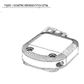
- a trim piece ( Figure 7) may be inserted into the front of the case.
- the trim piece includes two pins 71, which extend into the potting and lock the piece in place once the potting has set. Furthermore the trim piece acts to ensure that the sensor manifolds have been seated into their proper position before the potting sets.
- clips 72 may be moulded onto the front adapters which engage into notches 73 in the rear sensing/transmitter module. This would eliminate the need for screws and would speed up assembly and disassembly of the two parts of the device in the field.
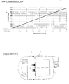
- the electronic sensing device may be factory calibrated to a virtually infinite number of pressure ranges 74.
- the current family of piezoresistive sensors has 7 different members ranging in pressure ranges from 0.34 to 17 bar. Any of these sensors may be used in this device.
- the device's sensing range does not have to line up exactly with the raw sensor's nominal ratings - ie. a device utilising a 0-1000 mbar sensor may be calibrated 0-500 mbar or 0-769 mbar.
- the cross sectional area of the holes and conduits are of great enough size so that they do not unduly restrict or create internal pressure losses which may be realised by momentary flow created in the conduit by fluctuations in pressure at the pressure source. Such fluctuation could affect the accuracy and/or response of the transmitter.
- the ends of the sensor manifolds/conduits 38,39 have a double O-ring seal to ensure that no leakage occurs between the rear sensing/transmitter module and the front adapter.
- the standard sensor as utilised in the standard design may be replaced by a higher end sensor with built in temperature compensation. By using the higher end sensor, no further changes are required to the device.
- Each rear sensing/transmitter module can be calibrated prior to assembly. Once calibrated, the unit is filled with potting compound thus eliminating the possibility of field calibration. This feature provides a lower product cost as a seal does not have to be made through the case for each tuning potentiometer. Additionally, the unit cannot be easily bumped out of adjustment.
- the rear sensing/transmitter module may utilise different electrical connectors including but not limited to:
Landscapes
- Physics & Mathematics (AREA)
- General Physics & Mathematics (AREA)
- Measuring Fluid Pressure (AREA)
Applications Claiming Priority (2)
| Application Number | Priority Date | Filing Date | Title |
|---|---|---|---|
| GBGB0101241.8A GB0101241D0 (en) | 2001-01-17 | 2001-01-17 | Electronic sensing device |
| GB0101241 | 2001-01-17 |
Publications (2)
| Publication Number | Publication Date |
|---|---|
| EP1225433A2 true EP1225433A2 (fr) | 2002-07-24 |
| EP1225433A3 EP1225433A3 (fr) | 2004-11-17 |
Family
ID=9907003
Family Applications (1)
| Application Number | Title | Priority Date | Filing Date |
|---|---|---|---|
| EP02250208A Withdrawn EP1225433A3 (fr) | 2001-01-17 | 2002-01-11 | Capteur de pression électronique |
Country Status (3)
| Country | Link |
|---|---|
| US (1) | US6662664B2 (fr) |
| EP (1) | EP1225433A3 (fr) |
| GB (1) | GB0101241D0 (fr) |
Cited By (1)
| Publication number | Priority date | Publication date | Assignee | Title |
|---|---|---|---|---|
| CN121577227A (zh) * | 2026-01-26 | 2026-02-27 | 深圳市科敏传感器有限公司 | 感测装置 |
Families Citing this family (8)
| Publication number | Priority date | Publication date | Assignee | Title |
|---|---|---|---|---|
| US7614307B2 (en) * | 2006-06-06 | 2009-11-10 | Eaton Corporation | Manifold assembly having a centralized pressure sensing package |
| US8037771B2 (en) * | 2009-05-13 | 2011-10-18 | Lsi Corporation | Electronic pressure-sensing device |
| US10393553B2 (en) * | 2016-02-25 | 2019-08-27 | Idex Health & Science Llc | Modular sensor system |
| US10401247B2 (en) * | 2016-08-02 | 2019-09-03 | Distech Controls Inc. | Differential pressure sensor arrangement for an environmental control system |
| US10466131B2 (en) | 2016-09-09 | 2019-11-05 | Distech Controls Inc. | System and bidrectional differential pressure sensor for adjusting measured pressure differential |
| US11789292B2 (en) | 2018-01-22 | 2023-10-17 | Johnson & Johnson Vision Care, Inc. | Ophthalmic lens with an optically non-coaxial zone for myopia control |
| US11768386B2 (en) | 2018-01-22 | 2023-09-26 | Johnson & Johnson Vision Care, Inc. | Ophthalmic lens with an optically non-coaxial zone for myopia control |
| US10901237B2 (en) | 2018-01-22 | 2021-01-26 | Johnson & Johnson Vision Care, Inc. | Ophthalmic lens with an optically non-coaxial zone for myopia control |
Family Cites Families (7)
| Publication number | Priority date | Publication date | Assignee | Title |
|---|---|---|---|---|
| GB1467957A (en) * | 1974-05-20 | 1977-03-23 | Hoke Inc | Mounting adaptor |
| US4131088A (en) * | 1976-11-08 | 1978-12-26 | The Bendix Corporation | Multiple function pressure sensor |
| US4582089A (en) * | 1984-10-31 | 1986-04-15 | General Screw Products Company | Valve manifold having a removable flange |
| US5069072A (en) * | 1990-07-26 | 1991-12-03 | Woodhead Industries, Inc. | Connector module for transducer |
| US5036884A (en) * | 1990-11-19 | 1991-08-06 | Keystone International Holdings Corp. | Mounting means for fluid pressure transmitters |
| US20010002552A1 (en) * | 1996-05-17 | 2001-06-07 | Peter Vinci | Digital remote gauge assembly |
| US6409969B1 (en) * | 1999-06-01 | 2002-06-25 | Cummins, Inc. | System and method for controlling a self-heated gas sensor based on sensor impedance |
-
2001
- 2001-01-17 GB GBGB0101241.8A patent/GB0101241D0/en not_active Ceased
-
2002
- 2002-01-11 EP EP02250208A patent/EP1225433A3/fr not_active Withdrawn
- 2002-01-14 US US10/043,139 patent/US6662664B2/en not_active Expired - Fee Related
Cited By (1)
| Publication number | Priority date | Publication date | Assignee | Title |
|---|---|---|---|---|
| CN121577227A (zh) * | 2026-01-26 | 2026-02-27 | 深圳市科敏传感器有限公司 | 感测装置 |
Also Published As
| Publication number | Publication date |
|---|---|
| US6662664B2 (en) | 2003-12-16 |
| US20020095993A1 (en) | 2002-07-25 |
| GB0101241D0 (en) | 2001-02-28 |
| EP1225433A3 (fr) | 2004-11-17 |
Similar Documents
| Publication | Publication Date | Title |
|---|---|---|
| US6119524A (en) | Measuring indicator device | |
| EP1216404B1 (fr) | Transducteur de processus modulable | |
| EP0720732B1 (fr) | Dispositif de mesure de deux pressions avec un transmetteur double | |
| JP6481053B2 (ja) | シールされた相互接続システムを有する端子ブロック | |
| EP3052899B1 (fr) | Transmetteur de variable de procédé comprenant un logement à double compartiment | |
| US5554809A (en) | Process detection apparatus | |
| US8334788B2 (en) | Process variable transmitter with display | |
| EP0829004B1 (fr) | Logement scelle sous pression | |
| US20110214504A1 (en) | Disposable pressure sensor systems and packages therefor | |
| US11692897B2 (en) | Field serviceable, small form-factor pressure scanner | |
| US20090116537A1 (en) | Combined temperature and pressure transducer incorporating connector keyway alignment and an alignment method | |
| US6840112B2 (en) | Differential pressure/pressure transmitter | |
| US6662664B2 (en) | Electronic pressure sensing device | |
| CN107990916B (zh) | 具有双隔室壳体的过程变量变送器 | |
| KR102282555B1 (ko) | 디지털 압력 게이지 교정용 지그 | |
| CN208635881U (zh) | 一种可更换显示位置的物位计 | |
| CN220063254U (zh) | 一种卫生型的压力变送器 | |
| CN211954540U (zh) | 一种智能单晶硅压力差压变送器 |
Legal Events
| Date | Code | Title | Description |
|---|---|---|---|
| PUAI | Public reference made under article 153(3) epc to a published international application that has entered the european phase |
Free format text: ORIGINAL CODE: 0009012 |
|
| AK | Designated contracting states |
Kind code of ref document: A2 Designated state(s): AT BE CH CY DE DK ES FI FR GB GR IE IT LI LU MC NL PT SE TR |
|
| AX | Request for extension of the european patent |
Free format text: AL;LT;LV;MK;RO;SI |
|
| PUAL | Search report despatched |
Free format text: ORIGINAL CODE: 0009013 |
|
| AK | Designated contracting states |
Kind code of ref document: A3 Designated state(s): AT BE CH CY DE DK ES FI FR GB GR IE IT LI LU MC NL PT SE TR |
|
| AX | Request for extension of the european patent |
Extension state: AL LT LV MK RO SI |
|
| AKX | Designation fees paid |
Designated state(s): AT BE CH CY DE DK ES FI FR GB GR IE IT LI LU MC NL PT SE TR |
|
| STAA | Information on the status of an ep patent application or granted ep patent |
Free format text: STATUS: THE APPLICATION IS DEEMED TO BE WITHDRAWN |
|
| 18D | Application deemed to be withdrawn |
Effective date: 20050518 |